- Page 1:
GTS 250 JOYMAX 250 SERVICE MANUAL F
- Page 5:
Serial Number Home page Contents
- Page 9 and 10:
1. General Information � The leng
- Page 11 and 12:
1. General Information � When sep
- Page 13:
1. General Information � Do not l
- Page 17 and 18:
1. General Information Troubles Dia
- Page 19 and 20:
1. General Information C. Engine ru
- Page 21: 1. General Information Lubrication
- Page 26: Primary adjustment is conducted fro
- Page 31 and 32: 2. Maintenance Information Steering
- Page 33: 2. Maintenance Information Brake Li
- Page 37 and 38: 2. Maintenance Information NAME Inn
- Page 39 and 40: 2. Maintenance Information Note: 2-
- Page 41: 3. Lubrication System Precautions i
- Page 46 and 47: Gear Oil Gear Oil Change Remove oil
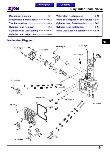
- Page 48 and 49: Mechanism Diagram .................
- Page 50: Trouble Diagnosis Poor engine start
- Page 55: 4. Fuel System Float Chamber Disass
- Page 59 and 60: 4. Fuel System Remove fuel tank upp
- Page 61 and 62: 4. Fuel System Air Cleaner Removal
- Page 63 and 64: 5. Removal & Installation of Engine
- Page 65 and 66: 5. Removal & Installation of Engine
- Page 67 and 68: 5. Removal & Installation of Engine
- Page 69 and 70: 5. Removal & Installation of Engine
- Page 71: 5. Removal & Installation of Engine
- Page 76: Remove the side cover mounting blot
- Page 82: Valve Seat Inspection and Service C
- Page 86: Install cylinder head side cover (3
- Page 90 and 91: Cylinder and Piston Removal Remove
- Page 93 and 94: 7. Cylinder / Piston Piston Ring In
- Page 96 and 97: Mechanism Diagram ········
- Page 98 and 99: Left Crankcase Cover Left crankcase
- Page 101 and 102: 8. V-Belt Driving System Installati
- Page 103 and 104: 8. V-Belt Driving System Inspection
- Page 105 and 106: 8. V-Belt Driving System Clutch Out
- Page 107 and 108: 8. V-Belt Driving System Clutch wei
- Page 109 and 110: 8. V-Belt Driving System Installati
- Page 111 and 112: 9. Final Driving Mechanism Precauti
- Page 113 and 114: 9. Final Driving Mechanism Inspecti
- Page 115 and 116: 9. Final Driving Mechanism Install
- Page 117 and 118: 9. Final Driving Mechanism Re-Assem
- Page 119 and 120: 10. Alternator / Starting Clutch Pr
- Page 121 and 122: 10. Alternator / Starting Clutch AC
- Page 123 and 124:
10. Alternator / Starting Clutch St
- Page 125 and 126:
10. Alternator / Starting Clutch AC
- Page 127 and 128:
10. Alternator / Starting Clutch No
- Page 130 and 131:
Disassembly of Crankcase Remove the
- Page 132 and 133:
Measure the clearance of the big en
- Page 134 and 135:
Hold left crank shaft puller, and t
- Page 136:
Mechanism Diagram ········
- Page 141 and 142:
12. Cooling System Check reserve ta
- Page 143 and 144:
12. Cooling System Water Pump Check
- Page 145 and 146:
12. Cooling System Install the new
- Page 147:
12. Cooling System Thermostat Pleas
- Page 150 and 151:
Mechanism Diagram·········
- Page 152 and 153:
Handle Cover Remove Loosen the 2 sc
- Page 154 and 155:
Loosen 2 bolts from the front cover
- Page 156 and 157:
Inner Box Remove Remove wind screen
- Page 158 and 159:
Side Cover Remove Loosen 2 screws f
- Page 160 and 161:
Luggage Box Remove Open the seat. L
- Page 162 and 163:
Floor Panel Remove Remove wind scre
- Page 164:
Mechanism Diagram·········
- Page 167 and 168:
14. Brake System Disk Brake System
- Page 169 and 170:
14. Brake System Brake fluid replac
- Page 171 and 172:
14. Brake System Rear Brake Caliper
- Page 173 and 174:
14. Brake System Remove the rubber
- Page 175 and 176:
14. Brake System Note: 14-12 To thi
- Page 178 and 179:
Steering Handle Remove Remove the r
- Page 180 and 181:
Front Wheel Loosen 2 bolts from the
- Page 182 and 183:
Assembly Fill out the block of bear
- Page 184 and 185:
Steering Stem Remove Remove handle,
- Page 186 and 187:
Mechanism Diagram·········
- Page 188 and 189:
Muffler Removal Loosen the 2 nuts f
- Page 190 and 191:
Rear Fork Inspection rear fork bear
- Page 192 and 193:
Mechanism Diagram ········
- Page 194:
Trouble Diagnosis No voltage � Ba
- Page 198 and 199:
Inspection on AC. Generator coil Re
- Page 201 and 202:
17. Electrical System Inspection on
- Page 203 and 204:
17. Electrical System Disconnect th
- Page 205 and 206:
17. Electrical System Removal of me
- Page 207 and 208:
17. Electrical System Replacement h
- Page 209:
17. Electrical System Replacement t
- Page 212:
Fuel Unit Open the seat. Remove the
- Page 216 and 217:
Home page Contents 18. Electrical D