

PA50, 55 & 60 ECO MK2 - Operator Manual - McConnel
PA50, 55 & 60 ECO MK2 - Operator Manual - McConnel
PA50, 55 & 60 ECO MK2 - Operator Manual - McConnel
- No tags were found...

Create successful ePaper yourself
Turn your PDF publications into a flip-book with our unique Google optimized e-Paper software.
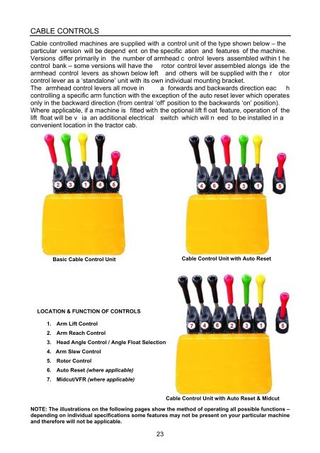
CABLE CONTROLSCable controlled machines are supplied with a control unit of the type shown below – theparticular version will be depend ent on the specific ation and features of the machine.Versions differ primarily in the number of armhead c ontrol levers assembled within t hecontrol bank – some versions will have the rotor control lever assembled alongs ide thearmhead control levers as shown below left and others will be supplied with the r otorcontrol lever as a ‘standalone’ unit with its own individual mounting bracket.The armhead control levers all move in a forwards and backwards direction eac hcontrolling a specific arm function with the exception of the auto reset lever which operatesonly in the backward direction (from central ‘off’ position to the backwards ‘on’ position).Where applicable, if a machine is fitted with the optional lift fl oat feature, operation of thelift float will be v ia an additional electrical switch which will n eed to be installed in aconvenient location in the tractor cab.Basic Cable Control UnitCable Control Unit with Auto ResetLOCATION & FUNCTION OF CONTROLS1. Arm Lift Control2. Arm Reach Control3. Head Angle Control / Angle Float Selection4. Arm Slew Control5. Rotor Control6. Auto Reset (where applicable)7. Midcut/VFR (where applicable)23Cable Control Unit with Auto Reset & MidcutNOTE: The illustrations on the following pages show the method of operating all possible functions –depending on individual specifications some features may not be present on your particular machineand therefore will not be applicable.


