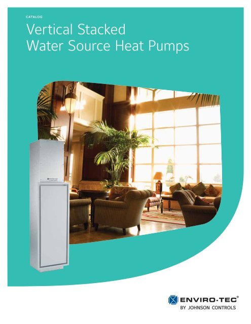
Vertical Stacked Water Source Heat Pumps, Catalog ... - Enviro-Tec
Vertical Stacked Water Source Heat Pumps, Catalog ... - Enviro-Tec
Vertical Stacked Water Source Heat Pumps, Catalog ... - Enviro-Tec
- No tags were found...

Create successful ePaper yourself
Turn your PDF publications into a flip-book with our unique Google optimized e-Paper software.
catalog<strong>Vertical</strong> <strong>Stacked</strong><strong>Water</strong> <strong>Source</strong> <strong>Heat</strong> <strong>Pumps</strong>
<strong>Catalog</strong>: ET145.00-EG5 (709)TABLE OF CONTENTS<strong>Vertical</strong> <strong>Stacked</strong> <strong>Water</strong> <strong>Source</strong> <strong>Heat</strong> <strong>Pumps</strong>Introduction . . . . . . . . . . . . . . . . . . . . . . . . . . . . . . . . . . . . . . . . . . . . . . . . . . . . . . . . . . . . . . . . . . . . . . . . . . . . . . . 3Product Overview . . . . . . . . . . . . . . . . . . . . . . . . . . . . . . . . . . . . . . . . . . . . . . . . . . . . . . . . . . . . . . . . . . . . . . . . . . 3Specifications . . . . . . . . . . . . . . . . . . . . . . . . . . . . . . . . . . . . . . . . . . . . . . . . . . . . . . . . . . . . . . . . . . . . . . . . . . . . . 4Nomenclature . . . . . . . . . . . . . . . . . . . . . . . . . . . . . . . . . . . . . . . . . . . . . . . . . . . . . . . . . . . . . . . . . . . . . . . . . . . . . 6Physical Data . . . . . . . . . . . . . . . . . . . . . . . . . . . . . . . . . . . . . . . . . . . . . . . . . . . . . . . . . . . . . . . . . . . . . . . . . . . . . 8AHRI Performance Data. . . . . . . . . . . . . . . . . . . . . . . . . . . . . . . . . . . . . . . . . . . . . . . . . . . . . . . . . . . . . . . . . . . . . 9Performance Data . . . . . . . . . . . . . . . . . . . . . . . . . . . . . . . . . . . . . . . . . . . . . . . . . . . . . . . . . . . . . . . . . . . . . . . . 10Blower Performance. . . . . . . . . . . . . . . . . . . . . . . . . . . . . . . . . . . . . . . . . . . . . . . . . . . . . . . . . . . . . . . . . . . . . . . 14Dimensional Data . . . . . . . . . . . . . . . . . . . . . . . . . . . . . . . . . . . . . . . . . . . . . . . . . . . . . . . . . . . . . . . . . . . . . . . . . 15Discharge Configurations . . . . . . . . . . . . . . . . . . . . . . . . . . . . . . . . . . . . . . . . . . . . . . . . . . . . . . . . . . . . . . . . . . . 19Wiring Diagram. . . . . . . . . . . . . . . . . . . . . . . . . . . . . . . . . . . . . . . . . . . . . . . . . . . . . . . . . . . . . . . . . . . . . . . . . . . 222 Johnson Controls
<strong>Vertical</strong> <strong>Stacked</strong> <strong>Water</strong> <strong>Source</strong> <strong>Heat</strong> <strong>Pumps</strong> <strong>Catalog</strong>: ET145.00-EG5 (709)SPECIFICATIONSmal overload protection. The fan motors are attached to theblower housings by means of an integral ‘flex-mount’ system,with additional vibration isolation provided by rubber mountinggrommets. A manual selector switch is accessible through thehinged return air panel, allowing switching between the twoavailable fan speeds (Hi – Low).• Optional Hi-Static motor and blower assembly, for applicationswith extended ductwork layout.ELECTRICAL/CONTROLSAll units are completely factory wired with all necessary operatingcontrols.• Optional non-fused electrical disconnect for service convenienceand maintenance.• Optional non-fused electrical disconnect with fusing addedto the internal line voltage switch circuit for service convenienceand maintenance.Standard unit control consists of a 24-volt electromechanicalrelay package. The cabinet mounted electrical box containsa 50VA Class II transformer for field connection. The reversingvalve solenoid coil shall be energized in cooling modeonly.Unit shall have a microprocessor-based control system withthe following:a. Unit shall operate with conventional thermostatdesigns.b. Unit shall incorporate a lockout circuit which provides resetcapability at the space thermostat, base unit, or by interruptingservice power, should any of the following standardsafety devices trip and shut off the compressor.c. Loss-of-charge/Low-pressure switchd. High-pressure switche. Control board shall monitor each refrigerantsafety switch independently.f. Low water temperature protectiong. Condensate overflow protectionh. Low voltage (brown-out) protectioni. Anti-short cycle timer (ASCT)j. Random startk. Should the high-pressure or low-pressure safeties openthree times within two hours of operation (1 hour forlow-pressure safety), then lockout requiring manual resetwill occur.l. Should the low water temperature or condensate overflowsafeties trip 3 times sequentially, then lockoutrequiring manual reset will occur.m. The low-pressure switch shall not be monitored duringthe initial 30 seconds of a cooling system's operation toprevent nuisance trips.n. Unit shall have capability to defeat time delays for servicing.o. Unit control board shall have on-board diagnostics andfault code display.p. Control board shall retain last 5 fault codes in nonvolatile memory which will not be lost in the event of apower loss.q. Unit shall have an automated sequence used after installationthat quickly tests cooling and heating modes.The unit’s thermostat wire leads will terminate in a 6-pin Molexplug for direct surface mount thermostat application. Thecontrol leads are spliced to field supplied cable for remotethermostat applications.ACOUSTIC RETURN AIR PANELThe flush-mounted return air panel is designed to minimizeline-of-sight noise transmission. The panel assembly is fabricatedfrom heavy gauge steel. An insulated, hinged centersection allows convenient user access to the unit control paneland filter.The perimeter frame of the panel is mounted to the drywall/framing opening at the front of the cabinet. The heat-pumpchassis is fully accessible and removable through the hingeddoor section. The panel is supplied pre-primed, ready forpainting.SUPPLY AIR GRILLESSupply air grilles shall be supplied for each free dischargeoutlet directly from the cabinet (non-ducted outlets). All unitmounted supply grilles will be supplied as double deflectiontype. Grilles for unequal airflow applications shall be providedwith integral opposed blade dampers. Grilles will be suppliedin standard 'Appliance White' painted finish.FILTERSAll units are supplied with a 1-inch thick throwaway filter.Filters are accessible through the hinged return air panel,without removing the inner service panel.UNIT TAGGINGEach unit shall be individually tagged with factory and customersupplied information. Units can be tagged withspecific room number, riser number, or any other specialrequirement of the project.FIELD INSTALLED ACCESSORIESThe following options are available field installation:• Hoses: high-pressure flexible hoses, with quick-sealingswivel couplings, provide supply and return water connectionsto the chassis. Hose material is fire-rated (UL-94 VO)thermoplastic inner tube, reinforced by a stainless steel wireouter braid. The hose assemblies are rated for a minimum350 psig working pressure.• Electronic Thermostats• Programmable (7-day), 1 Ht / 1 Cl, back-lit display. Thethermostat shall be supplied with an occupancy sensingcover (or be capable of being retrofitted on site for futureoccupancy sensing).• Non-programmable, 1 Ht / 1 Cl, back-lit display. Thethermostat shall be supplied with an occupancy sensingcover (or be capable of being retrofitted on site for futureoccupancy sensing).Johnson Controls 5
<strong>Catalog</strong>: ET145.00-EG5 (709)NOMENCLATURE<strong>Vertical</strong> <strong>Stacked</strong> <strong>Water</strong> <strong>Source</strong> <strong>Heat</strong> <strong>Pumps</strong>VERTICAL STACKED WATER SOURCE HEAT PUMP - CABINET1,2 3,4 5 6 7VB 12M 1 D A8 9 10 11,12 13 14 15A 2 2T 4 0 AProduct CategoryVB = Vert. <strong>Stacked</strong> <strong>Heat</strong> Pump -Standard Cabinet AssemblyVM = Vert. <strong>Stacked</strong> <strong>Heat</strong> Pump -Master Cabinet AssemblyVS = Vert. <strong>Stacked</strong> <strong>Heat</strong> Pump -Slave Cabinet AssemblyMisc. Options0 = NoneDesign SeriesA = CurrentUnit Capacity09 = .75 TON12 = 1 TON18 = 1.5 TON Horizontal Discharge Opening Orientation24 = 2 TON30 = 2.5 TON00, 0TX = None1H, 1TB = Back2H, 2T1 = Left + Front3H, 3T7 = Front + Left + Right36 = 3 TON F = Front 2 = Left + Back 8 = Front + Right + BackL = Left 3 = Left + Right 9 = Front + Left + BackR = Right 4 = Right + BackControl Options5 = Right + FrontM = Std Microprocessor Control6 = Back + FrontP = Microprocessor Control w/ Surface-Mount T-stat ConnectionSupply Air Configuration1H = Single Horizontal Supply2H = Double Horizontal Supply3H = Triple Horizontal SupplyVoltage0T = Top Only1 = 208/230-60-1 1T = Single Horizontal Supply + Top6 = 265-60-1 2T = Double Horizontal Supply + Top3T = Triple Horizontal Supply + Top00 = Field Cut (No Openings)Electrical Connection0 = None (Terminal Block)D = Non-Fused DisconnectF = Disconnect w/FusesRiser Arrangement1 = Right Hand Risers2 = Left Hand Risers3 = Back RisersBlower Options4 = R/Hand Risers with CoverA = Standard5 = L/Hand Risers with CoverB = Hi-Static BlowerCabinet Options6 = Back Risers with CoverA = Standard Assembly (88-in)6 Johnson Controls
<strong>Vertical</strong> <strong>Stacked</strong> <strong>Water</strong> <strong>Source</strong> <strong>Heat</strong> <strong>Pumps</strong> <strong>Catalog</strong>: ET145.00-EG5 (709)NOMENCLATUREVERTICAL STACKED WATER SOURCE HEAT PUMP - CHASSIS1,2,3,4 5,6 7 8 9 10 11 12 13VSCS 12 A 1 0 0 A C 0Product CategoryVSCS = Vert. <strong>Stacked</strong> HP Chassis R-410Misc. Options0 = NoneUnit Capacity09 = .75 TON12 = 1 TON18 = 1.5 TON24 = 2 TON30 = 2.5 TON36 = 3 TONDesign SeriesA = Current<strong>Water</strong>side OptionsA = Std <strong>Water</strong> CoilN = Cupro-nickel <strong>Water</strong> CoilVoltage1 = 208/230-60-16 = 265-60-1Airside OptionsA = Std Airside coilC = Corrosion Protective Coating<strong>Water</strong> Valve Options0 = No <strong>Water</strong> Control ValveM = Motorized 2-Way Shut-Off ValveAuto-Flow Regulator0 = No Flow Control ValveB = 1.5 USGPMC = 2.0 USGPMD = 2.5 USGPME = 3.0 USGPMF = 3.50 USGPMH = 4.0 USGPMJ = 4.5 USGPMK = 5.0 USGPML = 6.0 USGPMM = 7.0 USGPMN = 8.0 USGPMP = 9.0 USGPMR = 10.0 USGPMJohnson Controls 7
<strong>Catalog</strong>: ET145.00-EG5 (709)PHYSICAL DATA<strong>Vertical</strong> <strong>Stacked</strong> <strong>Water</strong> <strong>Source</strong> <strong>Heat</strong> <strong>Pumps</strong>VSCS SERIESModel Series 09 12 18 24 30 36Nominal Cooling (Ton) 1 0.75 1.0 1.5 2.0 2.5 3.0Compressor-Type Rotary ScrollR-410A Refrigerant Charge (oz) 22 26 38 42 49 52Air Coil-TypeEnhanced Copper tubes, Enhanced Aluminum FinsFace Area(sq ft) 1.46 1.56 2.35 2.63 3.33 3.33Rows/FPI 2/16 3/14 3/14 3/14 3/14 3/14<strong>Water</strong> Coil-TypeEnhanced Surface Co-AxialChassis Connection Size (in) 1/2 1/2 1/2 3/4 3/4 3/4Standard Blower / MotorDWDI Forward-Curved Centrifugal / PSC Direct-DriveDiameter x Width (in) 9x4T 9x4T 9x7T 9x7 9x8 9x8Motor HP 0.10 0.10 0.17 0.25 0.33 0.50HI-Static Blower / MotorDWDI Forward-Curved Centrifugal / PSC Direct-DriveDiameter x Width (in) 9x4T 9x4T 9x7T 10x7T 10x8T 10x8TMotor HP 0.10 0.17 0.25 0.33 0.33 0.50Filter Quantity-Size (in) 1-14x25x1 1-14x25x1 1-16x30x1 1-16x30x1 1-20x30x1 1-20x30x1Cabinet Weight (lb) 2 130 130 145 150 175 175Chassis Weight (lb) 70 75 100 140 155 160NOTE:1. Nominal Capacity calculated in accordance with AHRI / ISO Standard 13256-1 for <strong>Water</strong> Loop Application2. Cabinet weight is approximate and does not include weight of risersOPERATING LIMITS*COOLING HEATINGMin. Entering <strong>Water</strong> 30ºF 20ºFMax. Entering <strong>Water</strong> 110ºF 90ºF*Units are capable of operation with an entering fluid temperature range of 20ºF to 110ºF8 Johnson Controls
<strong>Vertical</strong> <strong>Stacked</strong> <strong>Water</strong> <strong>Source</strong> <strong>Heat</strong> <strong>Pumps</strong> <strong>Catalog</strong>: ET145.00-EG5 (709)AHRI/ISO PERFORMANCE DATAAHRI/ISO 13256-1 WATER LOOP CONDITIONS*ModelRatedFlow Rate(USGPM)RatedAir Flow(SCFM)CoolingCapacity(Btuh)SensibleCapacity(Btuh)EER<strong>Heat</strong>ingCapacity(Btuh)09 2.6 340 8,900 7,200 13.0 11,800 4.712 3.2 430 12,200 9,400 13.0 14,900 4.418 4.8 685 18,100 14,300 13.2 22,300 4.624 6.2 850 24,400 18,600 13.4 30,200 4.630 7.8 1075 29,700 22,900 13.3 33,900 4.436 9.5 1220 34,900 26,600 12.8 36,400 4.3*<strong>Water</strong> Loop capacities are rated at 86ºF EWT Cooling, 68ºF EWT <strong>Heat</strong>ing.COPAHRI/ISO 13256-1 GROUND WATER CONDITIONS*ModelRatedFlow Rate(USGPM)RatedAir Flow(SCFM)CoolingCapacity(Btuh)SensibleCapacity(Btuh)EER<strong>Heat</strong>ingCapacity(Btuh)09 2.6 340 10,100 7,600 19.5 9,300 3.912 3.2 430 14,400 10,600 19.8 12,200 3.618 4.8 685 20,900 15,500 20.6 17,900 4.024 6.2 850 27,600 20,300 21.5 23,800 3.830 7.8 1075 33,500 24,800 20.5 27,500 3.636 9.5 1220 39,200 28,800 19.4 29,100 3.6*Ground <strong>Water</strong> capacities are rated at 59ºF EWT Cooling, 50ºF EWT <strong>Heat</strong>ing.COPAHRI/ISO 13256-1 GROUND LOOP CONDITIONS*ModelRatedFlow Rate(USGPM)RatedAir Flow(SCFM)CoolingCapacity(Btuh)SensibleCapacity(Btuh)EER<strong>Heat</strong>ingCapacity(Btuh)09 2.6 340 9,300 7,300 14.2 7,000 3.112 3.2 430 13,100 9,800 14.5 9,600 3.118 4.8 685 18,800 14,500 15.2 14,000 3.124 6.2 850 25,900 19,200 15.7 18,100 3.130 7.8 1075 31,800 24,200 15.2 20,500 3.136 9.5 1220 36,400 27,200 14.0 22,900 3.1*Ground Loop capacities are rated at 77ºF EFT Cooling, 32ºF EFT <strong>Heat</strong>ing.COPNOTE:1. All Cooling capacities based upon 80.6ºF DB, 66.2ºF WB entering air temperature.2. All <strong>Heat</strong>ing capacities based upon 68ºF DB, 59ºF WB entering air temperature.Johnson Controls 9
<strong>Vertical</strong> <strong>Stacked</strong> <strong>Water</strong> <strong>Source</strong> <strong>Heat</strong> <strong>Pumps</strong> <strong>Catalog</strong>: ET145.00-EG5 (709)PERFORMANCE DATAVSCS18 — 685 CFMEWT (F) GPMWPD COOLING HEATINGPSI FT TC SC kW HR EER HTG kW HE LAT (F) COP20 4.8 7.5 17.3 11.4 1.29 7.0 85.4 2.62.4 2.0 4.7 22.2 15.1 0.75 24.7 29.7 13.0 1.30 8.6 87.6 2.930 3.6 4.3 9.9 22.3 15.2 0.72 24.7 31.1 13.5 1.30 9.1 88.5 3.14.8 7.3 16.8 22.6 15.6 0.69 25.0 33.0 13.9 1.32 9.4 88.9 3.12.4 1.9 4.5 21.3 14.9 0.88 24.3 24.2 14.6 1.30 10.2 90.0 3.340 3.6 4.1 9.5 21.5 15.3 0.83 24.4 25.9 14.9 1.31 10.5 91.0 3.44.8 7.0 16.1 21.9 15.8 0.80 24.6 27.5 15.5 1.33 10.9 91.6 3.42.4 1.9 4.3 20.5 14.8 0.98 23.9 20.9 16.6 1.31 12.1 92.4 3.750 3.6 3.9 9.1 21.5 15.7 0.91 24.6 23.5 17.3 1.32 12.8 93.5 3.84.8 6.7 15.5 21.3 15.5 0.88 24.2 24.3 18.0 1.33 13.4 94.2 4.02.4 1.6 3.8 19.7 14.4 1.14 23.6 17.3 19.0 1.32 14.4 95.6 4.260 3.6 3.5 8.0 20.5 14.9 1.07 24.1 19.2 19.8 1.34 15.2 96.7 4.34.8 5.9 13.6 20.8 15.4 1.02 24.3 20.4 20.3 1.37 15.7 97.4 4.42.4 1.5 3.5 18.9 14.1 1.29 23.3 14.6 21.2 1.34 16.6 98.8 4.670 3.6 3.2 7.3 19.1 14.5 1.22 23.3 15.7 22.1 1.36 17.5 99.9 4.84.8 5.4 12.5 19.4 14.9 1.18 23.4 16.4 22.8 1.39 18.1 100.5 4.82.4 1.4 3.3 17.8 13.4 1.45 22.7 12.3 23.2 1.35 18.6 101.1 5.080 3.6 3.0 7.0 18.2 14.0 1.36 22.8 13.3 24.2 1.38 19.5 102.7 5.24.8 5.2 11.9 18.6 14.7 1.27 22.9 14.7 25.2 1.40 20.5 103.5 5.32.4 1.4 3.1 17.0 13.1 1.64 22.6 10.4 24.9 1.37 20.2 103.3 5.390 3.6 2.9 6.6 17.4 13.6 1.55 22.7 11.3 25.8 1.39 21.1 104.5 5.44.8 4.9 11.3 17.8 14.1 1.46 22.8 12.2 27.7 1.41 22.8 105.6 5.72.4 1.3 3.0 15.8 12.3 1.82 22.0 8.6100 3.6 2.8 6.5 16.3 12.7 1.72 22.1 9.44.8 4.8 11.1 17.0 13.4 1.67 22.7 10.22.4 1.2 2.8 14.9 11.6 2.08 22.0 7.2110 3.6 2.7 6.2 15.4 12.2 1.96 22.1 7.94.8 4.7 10.8 16.2 13.0 1.90 22.7 8.5VSCS24 — 850 CFMEWT (F) GPMWPD COOLING HEATINGPSI FT TC SC kW HR EER HTG kW HE LAT (F) COP20 6.2 6.6 15.2 13.9 1.64 8.3 85.3 2.53.1 1.7 4.0 29.2 19.3 1.12 33.0 26.1 15.7 1.65 10.1 87.1 2.830 4.6 3.6 8.3 29.4 20.0 1.08 33.1 27.2 17.2 1.66 11.5 89.0 3.06.2 6.3 14.4 29.6 20.4 1.05 33.2 28.3 17.5 1.67 11.8 89.7 3.13.1 1.6 3.6 29.0 19.7 1.23 33.2 23.5 18.8 1.68 13.1 90.5 3.340 4.6 3.3 7.5 29.1 20.1 1.18 33.1 24.8 20.2 1.71 14.4 92.0 3.56.2 5.6 13.0 29.2 20.5 1.12 33.0 26.2 20.7 1.73 14.8 92.7 3.53.1 1.4 3.2 28.1 19.4 1.33 32.6 21.1 21.9 1.73 16.0 93.9 3.750 4.6 2.9 6.7 28.3 19.8 1.26 32.6 22.5 23.0 1.80 16.9 95.1 3.86.2 5.0 11.6 28.5 20.2 1.20 32.5 23.8 23.8 1.82 17.6 95.6 3.83.1 1.3 3.0 27.0 19.2 1.52 32.2 17.8 24.7 1.80 18.6 96.9 4.060 4.6 2.7 6.2 27.3 19.6 1.40 32.1 19.5 26.1 1.81 19.9 98.4 4.26.2 4.7 10.8 27.6 20.1 1.29 32.0 21.3 27.4 1.85 21.1 99.3 4.33.1 1.3 2.9 26.0 18.7 1.71 31.8 15.2 27.5 1.83 21.3 100.0 4.470 4.6 2.6 6.0 26.4 19.0 1.60 31.9 16.5 29.2 1.84 22.9 101.8 4.66.2 4.5 10.4 26.8 19.9 1.50 32.0 17.9 30.8 1.88 24.3 103.0 4.83.1 1.2 2.8 24.3 17.7 1.91 30.8 12.7 30.2 1.87 23.8 102.9 4.780 4.6 2.5 5.8 25.0 18.2 1.80 31.1 13.8 32.3 1.90 25.8 105.2 5.06.2 4.3 10.0 25.6 18.9 1.74 31.5 14.7 33.6 1.95 26.9 106.6 5.03.1 1.1 2.5 22.7 16.6 2.14 30.0 10.6 33.8 1.95 27.1 106.8 5.190 4.6 2.4 5.5 23.2 17.1 2.02 30.0 11.5 35.6 2.04 28.6 108.8 5.16.2 4.2 9.7 23.7 18.0 1.89 30.1 12.5 36.8 2.08 29.7 110.1 5.23.1 1.1 2.5 21.2 16.1 2.42 29.4 8.8100 4.6 2.3 5.3 21.7 16.5 2.28 29.4 9.56.2 4.2 9.7 22.1 17.0 2.17 29.5 10.23.1 1.0 2.3 19.8 15.2 2.70 29.0 7.3110 4.6 2.3 5.3 20.3 15.6 2.57 29.1 7.96.2 4.1 9.5 20.6 16.1 2.44 28.9 8.4• Cooling Performance is tabulated at 80.6 F DB and 66.2 F WB entering air. <strong>Heat</strong>ing peformance tabulated at 68 F EAT• Tabulated data does not include AHRI/ISO corrections for fan and pump power.• All capacities are expressed in MBH.• Insulated water circuit is recommended for operation below 60F EWT.• See performance correction tables for conditions beyond what is listed.• Extrapolation is not permissible.• Shaded areas indicate conditions where operation is not recommended.Johnson Controls 11
<strong>Catalog</strong>: ET145.00-EG5 (709)PERFORMANCE DATA<strong>Vertical</strong> <strong>Stacked</strong> <strong>Water</strong> <strong>Source</strong> <strong>Heat</strong> <strong>Pumps</strong>VSCS30 — 1075 CFMEWT (F) GPMWPD COOLING HEATINGPSI FT TC SC kW HR EER HTG kW HE LAT (F) COP20 3.9 5.6 12.9 17.4 1.89 10.9 84.6 2.73.9 1.5 3.5 34.8 23.7 1.37 39.5 25.4 20.4 1.92 13.8 87.3 3.130 5.8 3.1 7.2 35.3 24.4 1.35 39.9 26.2 21.1 1.95 14.5 88.1 3.27.8 5.4 12.5 35.6 24.9 1.33 40.1 26.8 21.9 1.96 15.2 89.3 3.33.9 1.4 3.2 35.3 24.3 1.45 40.2 24.3 21.9 1.98 15.2 90.2 3.240 5.8 2.9 6.6 35.7 25.4 1.41 40.6 25.3 22.9 2.04 15.9 91.1 3.37.8 5.0 11.4 35.8 25.8 1.37 40.5 26.1 23.8 2.09 16.7 92.2 3.33.9 1.2 2.9 34.0 24.5 1.52 39.2 22.4 25.3 2.08 18.2 93.1 3.650 5.8 2.6 6.0 34.4 25.1 1.48 39.4 23.3 26.5 2.16 19.2 94.2 3.67.8 4.5 10.4 34.5 25.5 1.46 39.5 23.7 28.6 2.21 21.1 95.1 3.83.9 1.2 2.8 32.9 24.0 1.72 38.8 19.2 29.5 2.14 22.2 95.9 4.060 5.8 2.5 5.8 33.4 24.7 1.68 39.1 19.9 31.1 2.20 23.6 97.1 4.17.8 4.3 10.0 33.4 24.7 1.64 39.0 20.3 32.3 2.24 24.7 97.9 4.23.9 1.2 2.7 31.2 22.8 1.91 37.7 16.4 32.8 2.19 25.3 98.8 4.470 5.8 2.4 5.6 31.7 23.5 1.83 38.0 17.3 34.5 2.24 26.9 100.0 4.57.8 4.2 9.6 32.3 24.3 1.90 38.8 17.0 35.8 2.25 28.1 100.7 4.73.9 1.1 2.6 29.7 21.9 2.14 37.0 13.8 34.9 2.20 27.4 100.7 4.680 5.8 2.3 5.4 30.2 22.7 2.06 37.2 14.7 36.1 2.25 28.4 101.5 4.77.8 4.0 9.3 31.0 23.6 2.15 38.3 14.5 36.9 2.26 29.2 101.9 4.83.9 1.0 2.4 28.1 21.1 2.38 36.2 11.8 36.4 2.22 28.8 101.9 4.890 5.8 2.2 5.0 28.7 21.8 2.35 36.7 12.2 37.3 2.26 29.5 102.2 4.87.8 3.8 8.7 28.8 22.2 2.30 36.6 12.5 37.7 2.27 30.0 102.5 4.93.9 1.3 3.0 25.2 19.2 2.67 34.3 9.5100 5.8 2.1 4.8 26.2 20.2 2.56 35.0 10.37.8 3.7 8.5 26.6 20.8 2.49 35.1 10.73.9 1.2 2.8 23.1 16.6 3.02 33.4 7.7110 5.8 2.0 4.6 24.5 17.4 2.89 34.4 8.57.8 3.6 8.3 24.7 19.5 2.82 34.3 8.8VSCS36 — 1220 CFMEWT (F) GPMWPD COOLING HEATINGPSI FT TC SC kW HR EER HTG kW HE LAT (F) COP20 9.5 9.1 21.0 18.3 1.99 11.5 81.9 2.74.8 2.6 6.0 42.4 29.3 1.68 48.1 25.2 20.7 2.08 13.7 83.7 2.930 7.2 5.4 12.5 42.6 29.0 1.60 48.1 26.6 21.5 2.09 14.3 84.3 3.09.5 8.5 19.6 42.8 28.6 1.58 48.1 27.1 22.0 2.10 14.8 84.7 3.14.8 2.5 5.8 41.2 30.0 1.81 47.4 22.7 24.2 2.10 17.0 86.4 3.440 7.2 5.0 11.5 41.6 29.9 1.72 47.5 24.1 25.2 2.12 17.9 87.1 3.59.5 8.0 18.5 42.0 29.4 1.68 47.7 25.0 26.0 2.13 18.7 87.8 3.64.8 2.3 5.3 39.2 29.0 1.91 45.8 20.5 27.6 2.14 20.3 88.9 3.850 7.2 4.6 10.6 40.0 29.2 1.82 46.2 22.0 28.8 2.17 21.3 89.8 3.99.5 7.4 17.1 40.5 29.1 1.77 46.5 22.9 29.2 2.34 21.2 90.2 3.74.8 2.1 4.8 37.3 27.6 2.18 44.7 17.1 30.2 2.39 22.1 90.9 3.760 7.2 4.3 9.9 38.5 28.1 2.06 45.5 18.7 31.9 2.40 23.8 92.2 3.99.5 6.9 15.9 39.1 28.5 2.00 45.9 19.6 33.3 2.41 25.1 93.3 4.04.8 2.0 4.6 35.0 26.6 2.44 43.3 14.3 34.2 2.42 26.0 94.0 4.170 7.2 4.1 9.5 36.7 27.5 2.38 44.8 15.4 36.1 2.46 27.7 95.4 4.39.5 6.6 15.2 37.5 27.7 2.30 45.3 16.3 36.9 2.47 28.5 96.0 4.44.8 1.8 4.2 33.5 26.1 2.80 43.0 12.0 36.9 2.52 28.3 96.0 4.380 7.2 3.9 9.0 35.0 27.0 2.74 44.3 12.8 38.9 2.54 30.2 97.5 4.59.5 6.3 14.5 35.9 27.1 2.60 44.7 13.8 39.8 2.55 31.1 98.2 4.64.8 1.7 3.9 31.9 25.2 3.14 42.6 10.2 39.7 2.57 30.9 98.1 4.590 7.2 3.7 8.5 33.2 25.6 2.89 43.1 11.5 41.3 2.60 32.4 99.4 4.79.5 6.0 13.8 34.2 26.1 2.78 43.7 12.3 42.1 2.62 33.2 100.0 4.74.8 1.6 3.7 29.5 23.3 3.31 40.8 8.9100 7.2 3.8 8.8 30.9 24.1 3.11 41.5 9.99.5 5.8 13.4 31.8 24.8 3.00 42.0 10.64.8 1.6 3.7 26.9 21.8 3.72 39.6 7.2110 7.2 3.7 8.5 28.2 22.5 3.42 39.8 8.29.5 5.7 13.1 28.9 22.8 3.35 40.3 8.6• Cooling Performance is tabulated at 80.6 F DB and 66.2 F WB entering air. <strong>Heat</strong>ing peformance tabulated at 68 F EAT• Tabulated data does not include AHRI/ISO corrections for fan and pump power.• All capacities are expressed in MBH.• Insulated water circuit is recommended for operation below 60F EWT.• See performance correction tables for conditions beyond what is listed.• Extrapolation is not permissible.• Shaded areas indicate conditions where operation is not recommended.12 Johnson Controls
<strong>Vertical</strong> <strong>Stacked</strong> <strong>Water</strong> <strong>Source</strong> <strong>Heat</strong> <strong>Pumps</strong> <strong>Catalog</strong>: ET145.00-EG5 (709)PERFORMANCE DATAANTIFREEZE CORRECTION TABLEEthyleneGlycolAntifreeze Concentration5% 10% 15% 20% 25% 30% 40%TC, SC 0.998 0.995 0.993 0.991 0.989 0.987 0.984HTG 0.995 0.990 0.985 0.980 0.974 0.969 0.964WPD 1.040 1.055 1.080 1.105 1.135 1.165 1.210PropyleneGlycolMethanolTC, SC 0.995 0.992 0.987 0.983 0.979 0.975 0.970HTG 0.989 0.982 0.975 0.967 0.958 0.951 0.943WPD 1.035 1.055 1.100 1.145 1.200 1.260 1.320TC, SC 0.999 0.995 0.990 0.986 0.982 0.980 0.978HTG 0.989 0.985 0.979 0.971 0.963 0.954 0.946WPD 1.050 1.072 1.094 1.116 1.140 1.165 1.196AIRFLOW CORRECTION TABLEAirflow %Cooling<strong>Heat</strong>ingTC SC kW HR HTG kW HE70 0.931 0.847 0.964 0.946 0.942 1.075 0.94075 0.941 0.872 0.969 0.956 0.953 1.059 0.94980 0.950 0.896 0.979 0.961 0.960 1.039 0.95885 0.966 0.923 0.983 0.971 0.970 1.023 0.96990 0.977 0.948 0.989 0.981 0.979 1.015 0.97995 0.989 0.974 0.995 0.990 0.989 1.007 0.989100 1.000 1.000 1.000 1.000 1.000 1.000 1.000105 1.008 1.025 1.006 1.010 1.009 0.994 1.010110 1.018 1.048 1.013 1.017 1.019 0.992 1.018115 1.026 1.070 1.019 1.026 1.029 0.991 1.028COOLING PERFORMANCE CORRECTION TABLEEATEAT DB (F) - SCTCWB (F)70 75 80.6 85 90 95HR60 0.845 0.86 1.1 1.305 S S S 0.90465 0.948 0.628 0.865 1.082 1.312 S S 0.97966.2 1 0.539 0.777 1 1.22 1.475 S 170 1.061 0.631 0.855 1.081 1.331 1.543 1.03975 1.162 0.618 0.848 1.09 1.296 1.107S = Sensible cooling is equal to Total CoolingHEATING PERFORMANCE CORRECTION TABLEEAT DB (F) HTG kW HE45 1.101 0.785 1.16250 1.080 0.832 1.12555 1.059 0.878 1.07960 1.039 0.926 1.06465 1.019 0.960 1.02368 1.000 1.000 1.00070 0.990 1.028 0.98375 0.974 1.064 0.95780 0.951 1.111 0.918Johnson Controls 13
<strong>Catalog</strong>: ET145.00-EG5 (709)BLOWER PERFORMANCE<strong>Vertical</strong> <strong>Stacked</strong> <strong>Water</strong> <strong>Source</strong> <strong>Heat</strong> <strong>Pumps</strong>STANDARD BLOWER PERFORMANCE (CFM)UnitSizeRatedCFM09 34012 43018 68524 85030 107536 1220Min. Max. MotorExternal Static Pressure (in w.g.)CFM CFM Speed 0 0.05 0.1 0.15 0.2 0.25 0.3 0.35 0.4 0.45 0.5238 345 HIGH 345 335 325 315 305 290 275 255 235 - -240 310 LOW 310 300 285 270 255 240 - - - - -301 435 HIGH 435 425 415 400 385 370 355 340 320 295 -301 345 LOW 345 335 325 315 305 300 - - - - -479.5 690 HIGH 690 675 660 635 615 595 575 550 525 495 460480 500 LOW 500 495 490 485 480 - - - - - -595 855 HIGH 855 835 815 795 770 740 710 680 650 615 595605 710 LOW 710 705 690 670 650 630 605 - - - -752.5 1075 HIGH 1075 1050 1020 990 960 930 895 850 800 750 -755 950 LOW 950 935 915 890 865 835 795 755 - - -870 1230 HIGH 1230 1200 1170 1140 1110 1075 1040 1000 960 915 870855 1115 LOW 1115 1100 1075 1050 1020 990 960 930 895 855 -HIGH STATIC BLOWER PERFORMANCE (CFM)UnitSizeRatedCFM09 34012 43018 68524 85030 107536 1220Min.CFMMax.CFMMotorSpeedExternal Static Pressure (in w.g.)0 0.05 0.1 0.15 0.2 0.25 0.3 0.35 0.4 0.45 0.5 0.55 0.6 0.65 0.7238 350 HIGH - - - 350 340 330 315 300 285 265 245 235 - - -240 330 LOW 330 320 310 300 290 280 270 255 240 - - - - - -315 455 HIGH - - - 455 440 425 410 395 380 360 340 315 - - -305 390 LOW 390 385 380 370 360 350 335 320 305 - - - - - -480 695 HIGH - - - 695 675 655 635 615 590 565 540 510 480 - -480 670 LOW 670 660 650 635 620 605 590 570 550 530 505 480 - - -650 865 HIGH - - - - - - 865 845 820 795 770 740 710 680 650605 795 LOW 795 785 775 760 745 730 715 695 675 655 630 605 - - -875 1090 HIGH - - - - - - 1090 1070 1050 1025 1000 970 940 910 875795 985 LOW 985 980 975 970 960 950 940 935 920 905 895 875 850 825 795945 1245 HIGH - - - - 1245 1220 1190 1160 1130 1100 1070 1040 1010 980 945875 1180 LOW 1180 1170 1160 1145 1130 1110 1090 1070 1050 1025 1000 970 940 910 875ELECTRICAL DATA - STANDARD BLOWERUnit SizeCOMPRESSORBLOWERMAX FUSE /SUPPLYMIN. CCT.CCT. BKR.VOLTAGE QTY RLA LRA HP FLA AMPACITYAMP09 208-230/1/60 1 @ 4.8 22.2 0.10 0.8 6.80 1512208-230/1/60 1 @ 6.7 32.5 0.10 0.8 9.18 15265/1/60 1 @ 4.6 20.0 0.10 0.7 6.45 1518208-230/1/60 1 @ 9.0 48.0 0.17 1.2 12.45 20265/1/60 1 @ 7.1 43.0 0.17 0.8 9.68 1524208-230/1/60 1 @ 12.8 58.3 0.25 1.5 17.50 30265/1/60 1 @ 9.6 54.0 0.25 1.3 13.30 2030208-230/1/60 1 @ 14.1 73.0 0.33 2.1 19.73 30265/1/60 1 @ 11.2 60.0 0.33 1.9 15.90 2536208-230/1/60 1 @ 16.7 79.0 0.50 2.7 23.58 40265/1/60 1 @ 13.5 72.0 0.50 2.2 19.08 30ELECTRICAL DATA - HIGH STATIC BLOWERUnit SizeCOMPRESSORBLOWERMAX FUSE /SUPPLYMIN. CCT.CCT. BKR.VOLTAGE QTY RLA LRA HP FLA AMPACITYAMP09 208-230/1/60 1 @ 4.8 22.2 0.10 0.8 6.80 1512208-230/1/60 1 @ 6.7 32.5 0.17 1.2 9.58 15265/1/60 1 @ 4.6 20.0 0.17 0.8 6.55 1518208-230/1/60 1 @ 9.0 48.0 0.25 1.5 12.75 20265/1/60 1 @ 7.1 43.0 0.25 1.3 10.18 1524208-230/1/60 1 @ 12.8 58.3 0.33 2.1 18.10 30265/1/60 1 @ 9.6 54.0 0.33 1.9 13.90 2030208-230/1/60 1 @ 14.1 73.0 0.33 2.1 19.73 30265/1/60 1 @ 11.2 60.0 0.33 1.9 15.90 2536208-230/1/60 1 @ 16.7 79.0 0.50 2.7 23.58 40265/1/60 1 @ 13.5 72.0 0.50 2.2 19.08 3014 Johnson Controls
<strong>Vertical</strong> <strong>Stacked</strong> <strong>Water</strong> <strong>Source</strong> <strong>Heat</strong> <strong>Pumps</strong> <strong>Catalog</strong>: ET145.00-EG5 (709)DIMENSIONAL DATASIDE RISER UNITSAB3"SEE NOTE (3)ABRSD1 1/2"A/2OPTIONAL 24VCONNECTION BOXFOR SURFACE-MOUNTTHERMOSTATØ7/8"POWER ENTRANCE(RH SIDE ONLY)4"4 1/4"4 1/4"1 1/2"RIGHT HAND UNITRSD48"60"50 1/2"6"Ø1/2"CONTROL ENTRANCE(BOTH SIDES)88"FLOOR TO FLOOR PLUS 2"4"LEFT HAND UNITØ1/2" CONDUITPOWER ENTRANCE6"PLAN VIEWCMODEL A B CSUPPLY ANDRETURN RISERSVSCS09VSCS12VSCS18VSCS24VSCS30VSCS3617ALL DIMENSIONS IN INCHES17 1620 20 1924 24 22FRONT VIEWNOTES:CONDENSATEDRAIN RISERRIGHT SIDE VIEW1) RETURN AIR OPENING SHALL BE ON FRONT OF UNIT.2) CUSTOMER SELECTABLE DISCHARGE ARRANGEMENTS SHALLBE AVAILABLE FOR SINGLE OR MULTI-DUCT INSTALLATIONS.ALL FACTORY CUT CABINET OPENINGS ARE FINISHED WITH A1-INCH DRYWALL/PLASTER FLANGE.3) RISER COVER IS OPTIONALJohnson Controls 15
<strong>Catalog</strong>: ET145.00-EG5 (709)DIMENSIONAL DATA<strong>Vertical</strong> <strong>Stacked</strong> <strong>Water</strong> <strong>Source</strong> <strong>Heat</strong> <strong>Pumps</strong>REAR RISER UNITSAB3"A/2SEE NOTE (3)R4 1/4"DS4"A/2OPTIONAL 24VCONNECTION BOXFOR SURFACE-MOUNTTHERMOSTAT1 1/2"PLAN VIEWØ1/2" CONDUITPOWER ENTRANCE1 1/2"88"C48"60"Ø7/8"POWER ENTRANCE(RH SIDE ONLY)6"Ø1/2"CONTROL ENTRANCE(BOTH SIDES)FLOOR TO FLOOR PLUS 2"50 1/2"MODEL A B CVSCS09VSCS121717 16VSCS18VSCS2420 20 196"VSCS30VSCS36ALL DIMENSIONS IN INCHES24 24 22AS REQ'DRETURN RISERSUPPLY RISERCONDENSATEDRAIN RISERFRONT VIEWRIGHT SIDE VIEWNOTES:1) RETURN AIR OPENING SHALL BE ON FRONT OF UNIT.2) CUSTOMER SELECTABLE DISCHARGE ARRANGEMENTS SHALLBE AVAILABLE FOR SINGLE OR MULTI-DUCT INSTALLATIONS.ALL FACTORY CUT CABINET OPENINGS ARE FINISHED WITH A1-INCH DRYWALL/PLASTER FLANGE.3) RISER COVER IS OPTIONAL16 Johnson Controls
<strong>Vertical</strong> <strong>Stacked</strong> <strong>Water</strong> <strong>Source</strong> <strong>Heat</strong> <strong>Pumps</strong> <strong>Catalog</strong>: ET145.00-EG5 (709)DIMENSIONAL DATAACOUSTIC RETURN AIR PANELAUNITSIZE A B C D E00901201802403003622 3/425 3/429 3/417201924 2316 16 1/419 1/423 1/4ALL DIMENSIONS ARE IN INCHES20 3/4 MIN.23 3/4 MIN.27 3/4 MIN.54 3/4"(52 3/4" WALL OPENING )Acoustic panel may be installed withhinge on right hand side, or left hand sideEBC2 1/2 MIN.DRYWALL1" R.A. PLASTER FRAMED4 MOUNTING SCREWSINSERTED THRU DRYWALLINTO STUDSFLUSH MOUNTEDACOUSTIC PANELACOUSTICPANEL3 3 4"6"1. IMPORTANT: For maximum R.A. flow, flush mounted acousticpanel must be centered vertically and horizontally over the ReturnAir opening of the cabinet. Supply air duct collar extensions maybe required to prevent short cycling.FLOORCABINET2. Acoustic panel is fabricated of "pre-primed" galvanized steel forfield painting by others.Johnson Controls 17
<strong>Catalog</strong>: ET145.00-EG5 (709)<strong>Vertical</strong> <strong>Stacked</strong> <strong>Water</strong> <strong>Source</strong> <strong>Heat</strong> <strong>Pumps</strong>DIMENSIONAL DATADISCHARGE GRILLEX1 1/2"H1 1/2XWFRONT OF UNITRecommended Supply Grille DimensionsMODEL Single Grille Double Grille Triple Grille Top DischargeSeries 100% CFM 50% CFM 33% CFM Up to 100% CFM009 14W x 8H 10W x 6H Not Recommended 12 x 12012 14W x 10H 10W x 8H Not Recommended 12 x 12018 16W x 12H 14W x 8H 14W x 6H 14 x 14024 16W x 14H 14W x 12H 14W x 8H 14 x 14030 Not Recommended 16W x 12H 14W x 10H 17 x 17036 Not Recommended 16W x 14H 14W x 12H 17 x 171) Unit mounted supply grilles will be supplied as double-deflection type.2) Grilles for unequal airflow applications (unit-mounted plus ducted supply) shall be provided with integralopposed-blade dampers.3) All grilles will be supplied in standard ‘Appliance White’ painted finish4) Grilles are shipped loose, for field installation upon completion of cabinet / ductwork / drywall installation.5) Top discharge, when combined with any other discharge arrangement, shall be included in determininggrille size (i.e. Top + Front arrangement – Front grille selected from ‘Double Grille’ column).18 Johnson Controls
<strong>Vertical</strong> <strong>Stacked</strong> <strong>Water</strong> <strong>Source</strong> <strong>Heat</strong> <strong>Pumps</strong> <strong>Catalog</strong>: ET145.00-EG5 (709)DISCHARGE CONFIGURATIONSRIGHT HAND RISERRRRRFRONT SLEFT SBACKSFIELDCUTSDDDDRA RA RA RATOP+FRONTRSTOP+LEFTRSTOP+BACKRSTOPONLYRSDDDDRA RA RA RARRRRFRONT+LEFTSDFRONT+BACKSDLEFT+BACKSD3-WAYSDRA RA RA RATOP+FRONT+LEFTRSDTOP+FRONT+BACKRSDTOP+BACK+LEFTRSDRA RA RANOTES:1) RETURN AIR OPENING SIDE IS DEFINED AS FRONT OF UNIT (CHASSIS AND CONTROL SERVICE ACCESS).2) 3-WAY DISCHARGE ARRANGEMENT IS NOT RECOMMENDED FOR UNIT SIZES 009, 0123) SINGLE DISCHARGE OPENING (EXCEPT TOP DISCHARGE) IS NOT RECOMMENDED FOR UNIT SIZES 030, 036Johnson Controls 19
<strong>Catalog</strong>: ET145.00-EG5 (709)DISCHARGE CONFIGURATIONS<strong>Vertical</strong> <strong>Stacked</strong> <strong>Water</strong> <strong>Source</strong> <strong>Heat</strong> <strong>Pumps</strong>LEFT HAND RISERRRRRSFRONTS RIGHT S BACKSFIELDCUTDDDDRA RA RA RARSTOP+FRONTRSTOP+RIGHTRSTOP+BACKRSTOPONLYDDDDRA RA RA RARRRRSDFRONT+RIGHTSDFRONT+BACKSDBACK+RIGHTSD3-WAYRA RA RA RARSDTOP+FRONT+RIGHTRSDTOP+FRONT+BACKRSDTOP+BACK+RIGHTRA RA RANOTES:1) RETURN AIR OPENING SIDE IS DEFINED AS FRONT OF UNIT (CHASSIS AND CONTROL SERVICE ACCESS).2) 3-WAY DISCHARGE ARRANGEMENT IS NOT RECOMMENDED FOR UNIT SIZES 009, 0123) SINGLE DISCHARGE OPENING (EXCEPT TOP DISCHARGE) IS NOT RECOMMENDED FOR UNIT SIZES 030, 03620 Johnson Controls
<strong>Vertical</strong> <strong>Stacked</strong> <strong>Water</strong> <strong>Source</strong> <strong>Heat</strong> <strong>Pumps</strong> <strong>Catalog</strong>: ET145.00-EG5 (709)DISCHARGE CONFIGURATIONSREAR RISERRD SR D SR D SR D SFRONTLEFT RIGHTFIELDCUTRA RA RA RARD SR D SR D SR D STOP+FRONTTOP+LEFTTOP+RIGHTTOPONLYRA RA RA RARD SR D SR D SR D SFRONT+LEFTFRONT+RIGHTLEFT+RIGHT3-WAYRA RA RA RARD SR D SR D STOP+FRONT+LEFTTOP+FRONT+RIGHTTOP+LEFT+RIGHTRA RA RANOTES:1) RETURN AIR OPENING SIDE IS DEFINED AS FRONT OF UNIT (CHASSIS AND CONTROL SERVICE ACCESS).2) 3-WAY DISCHARGE ARRANGEMENT IS NOT RECOMMENDED FOR UNIT SIZES 009, 0123) SINGLE DISCHARGE OPENING (EXCEPT TOP DISCHARGE) IS NOT RECOMMENDED FOR UNIT SIZES 030, 036Johnson Controls 21
<strong>Catalog</strong>: ET145.00-EG5 (709)WIRING DIAGRAM<strong>Vertical</strong> <strong>Stacked</strong> <strong>Water</strong> <strong>Source</strong> <strong>Heat</strong> <strong>Pumps</strong>22 Johnson Controls
<strong>Vertical</strong> <strong>Stacked</strong> <strong>Water</strong> <strong>Source</strong> <strong>Heat</strong> <strong>Pumps</strong> <strong>Catalog</strong>: ET145.00-EG5 (709)NOTESJohnson Controls 23
Printed on recycled paper<strong>Catalog</strong>: ET145.00-EG5 (709) Supersedes: ET145.00-EG5 (1108)© 2009 Johnson Controls, Inc. P.O. Box 423, Milwaukee, WI 53201 Printed in USAwww.johnsoncontrols.com