IOM - Enviro-Tec
IOM - Enviro-Tec
IOM - Enviro-Tec

You also want an ePaper? Increase the reach of your titles
YUMPU automatically turns print PDFs into web optimized ePapers that Google loves.
SERIES 600 ANALOGELECTRONIC CONTROLSwith 2" Thermostat SupplementINSTALLATION, OPERATIONAND BALANCING MANUALStock ID: <strong>IOM</strong>-600January, 1998©1998 <strong>Enviro</strong>nmental <strong>Tec</strong>hnologies, Inc.Largo, FL
TABLE OF CONTENTS1.0 DEFINITIONS AND DESCRIPTIONS1.2 Thermostat (Figure 1)........................................................................................................................ 41.2 Controller (Figure 2) ......................................................................................................................... 41.3 Actuator (Figure 3)............................................................................................................................ 52.0 INSTALLATION2.1 Inspection (Figure 4) ......................................................................................................................... 62.2 Coordination of Trades...................................................................................................................... 62.3 Thermostat Mounting (Figures 5, 6 & 7) .......................................................................................... 62.4 Wiring Installation............................................................................................................................. 82.5 Controller Wiring .............................................................................................................................. 82.6 Thermostat Wiring ............................................................................................................................ 83.0 STARTUP AND BALANCE PROCEDURE3.1 Initial Start-Up Procedure.................................................................................................................. 93.2 Balancing Procedures ........................................................................................................................ 94.0 TROUBLESHOOTING4.1 Damper Motion ............................................................................................................................... 124.2 Fan ................................................................................................................................................... 134.3 Electric Heat.................................................................................................................................... 144.4 Night Setback .................................................................................................................................. 154.5 Night Mode...................................................................................................................................... 164.6 SST/BT with Morning Warm-up..................................................................................................... 174.7 VVF/CVF with Morning Warm-up................................................................................................. 184.8 Changeover...................................................................................................................................... 194.9 No Response to Thermostat ............................................................................................................ 204.10 Corrective Actions........................................................................................................................... 215.0 WARRANTY POLICY ............................................................................................................................ 226.0 PARTS LIST6.1 Thermostat......................................................................................................................................... 236.2 Controller........................................................................................................................................... 236.3 Miscellaneous.................................................................................................................................... 267.0 APPENDIX A (ETST4H, 2" Thermostat Mounting Instructions)............................................................. 27
Thermostat (Figure 1)1.0 DEFINITIONS AND DESCRIPTIONS1.1 THERMOSTAT (FIGURE 1)a. Thermistor – Glass encapsulated, hermetically sealed temperature sensing device mounted on front ofthe thermostat printed circuit board.b. Setpoint Controls “A” and “B” – Green thumbwheel potentiometers mounted on front of the thermostatprinted circuit board. “A” adjusts temperature setpoint for day or cooling operation. “B” adjuststemperature setpoint for night (setback) or heating (changeover) operation.c. Enclosure – Protects thermostat and provides stable temperature environment for sensing. Vertical finson cover face must be on left hand side of enclosure directly over thermistor.d. Connectors – Captive screw type. Terminal designations are etched on solder side of printed circuitboard.e. Thermostat Packaging – Bubble pack design for protection during shipment. Terminal numbers, signaldesignations, serial number, inventory number and ETI job number are shown on outside of package.1.2 CONTROLLER (REFER TO FIGURE 2 - PAGE 5)a. Thermostat and Sensor Connectors - One-piece captive screw terminal type for reliable connections.b. 24 VAC and Control Output Connectors - Male, 1/4”, quick connect type.c. Labels - Computer printed with serial number, inventory number and ETI job number.d. D.C. Actuator Drive Terminal - Incorporates reversing and current limit circuitry which removes powerfrom motor when a mechanical stop is met.
Current Controller (Figure 2a) Old Controller (Figure 2b)(Refer to page 4) (No longer available)1.3 ACTUATOR (FIGURE 3)a. A.C. Motor – Hansen “Synchronization” model is actually two motors “pancaked” together, each with 24VAC, 5 W winding. The output at pinion gear is 1 RPM. White wires are used for common, blue wireconnects to CW motor, yellow to CCW motor. A 13 ohm resistor was provided on the controller toprevent damage by high voltage (used throughout 1990). Replacement rotary model is ETACTRTADS or,if position switch is required, ETACTRTADSA.b. D.C. Motor – Reversible D.C. motor. Output at pinion gear is approximately 2 RPM, depending on load.Connections are made using 3/16" quick connect receptacles (see 1.2.d above for drive circuitrydescription).c. Rack & Pinion Drive Train – Rack and pinion type with lubricated steel gear insert in rack for strength.Pin at end of rack attaches to damper shaft with bolt. Rack contains internal stops. Full travel time isapproximately 70 seconds for 45° damper travel (used through August 1992). This drive train with D.C.motor is no longer available. Replacement rotary model is ETACTRT or, if damper position switch isrequired, ETACTRTA.d. Rotary – 90° rotation. Slides over damper shaft and uses two set screws. Full travel time is 2 to 3minutes for 90° rotation. (Attach to damper shaft with approximately 1/8” gap between bottom ofactuator and bottom of control enclosure.)(c) Rack & Pinion TypeActuator (Figure 3)(d) Rotary Type
2.1 INSPECTION1 Units with electric heater, 3 tap switch is located inside heater cabinet.2 Units with electric heater, pressure switch is mounted on side of heater panel facing inlet collar.Typical Component Mounting (Figure 4)2.0 INSTALLATIONUpon receipt of VAV terminals, check controls for shipping damage such as loose or broken connectors, broken actuator orcontroller housing, loose or disconnected tubing and loose wiring. Also inspect both before and after installation fordamage caused by abuse or mishandling. A diagram of a typical control component mounting configuration is provided inFigure 4.2.2 COORDINATION OF TRADESContractor should see that all trades involved with both the VAV terminals and the electronic controls (includingthermostats) have a copy of the documentation and submitted control sequence data prior to installation.2.3 THERMOSTAT MOUNTINGThermostats are shipped separately from the terminal units via UPS or in the terminal control enclosure as per salesrepresentative request. The thermostat may be mounted directly to drywall or, optionally, to a horizontally mounted, singlegang junction box.2.3.1 Drywall Mounting (Figures 5 & 6.)a. Drill holes in wall for cable from controller and 2 wall anchors. Insert wall anchors in wall.b. Run cable through L-shaped hole in thermostat base and fasten base to wall with screws providedas shown in sketch.c. Mount PC Board on base so Setpoint Dial is at bottom between board and base (exposed set pointunit) or at top (standard unit). Use guide pins to align. Fasten PC Board to base using plasticretaining pins provided.d. Snap cover onto base making sure vertical slots are on left side (“ENVIRO-TEC ® “ is right sideup).2.3.2 Single Junction Box Mounting (Figure 7)a. Install right-hand screw (left-hand for exposed set point thermostat) through bracket & fix bracketto junction box.b. Install left-hand screw (right-hand for exposed set point thermostat) through thermostat base plateand bracket, into junction box. Do not tighten fully.c. Install center screw through thermostat base plate and bracket.d. Tighten screws. Mount PC Board on base per Step 2.3.1.c.e. Snap cover onto base making sure vertical slots are on left side (“ENVIRO-TEC ® ” is right sideup).
Standard(Figure 5)Exposed Setpoint(Figure 6)Single JunctionBox(Figure 7)
2.4 WIRING INSTALLATIONWARNING – Disconnect all power supplies to the system before wiring to avoid damage to theequipment or possible electrical shock.a. Required wire type for external control connections – 18 to 20 AWG stranded copper.b. Wiring diagrams – Refer to ENVIRO-TEC ®. Submittal Data to determine correct terminals forwiring. A copy of the wiring diagram submittal may be obtained from the sales representative.Before beginning wiring, ensure that submittal sequence matches the control model number.(Refer to parts in Section 6).c. Control wiring to thermostat and optional remote contact closures should not be routed close topower (line voltage) wiring, electrical machinery or lighting, to reduce the possibility of electricalinterference.2.5 CONTROLLER WIRINGa. Thermostat and Control Input Connections:1. Using a small screwdriver, turn screw fully CCW.2. Insert stripped wire(s) 18-20 AWG stranded copper(Figure 8).3. Turn screw fully CW. Make sure connector clampsuninsulated portion of wire.b. VAC Input and Control Output Connections:1. Strip ¼" of insulation from 18-20 AWG stranded copper wire.2. Attach a ¼" quick connect receptacle to the uninsulated portion of the wire using a set ofcrimpers.3. Push receptacle over spade on printed circuit board. CAUTION – Fit is tight. If removal isrequired, do not wiggle or pull; carefully pry off with a screw driver.2.6 THERMOSTAT WIRINGa. Remove cover from thermostat. If a locking cover has been provided, a 1/16 inch allen wrenchwill be required to remove the two allen screws which lock the cover in place.b. Remove printed circuit board from base. If plastic retaining pins are tight, pry up the pins with asmall screwdriver. CAUTION – Take care not to damage components on printed circuit boardwhen prying out plastic retaining pins.c. Strip ¼ inch of insulation from the wire.Screw TerminalConnector(Figure 8)d. Insert wire in connector and tighten screw. CAUTION – Do not overtighten screws. Make sureconnector clamps uninsulated portion of wire.e. Repeat Steps c and d for all wires and terminals. Each terminal present should have a single wireinserted when wiring is complete.f. Replace board on base using guide pins to align. Insert plastic retaining pins into large holes inprinted circuit board and push through into base.g. Replace cover, making sure vertical openings on face are positioned on left side. If the cover islocking, reinsert allen screws removed in Step (a) so that cover cannot be removed.CAUTION – Always verify that wiring is correct before applying power.
3.0 START-UP & BALANCE PROCEDURE3.1 INITIAL START-UP PROCEDUREWARNING – Lethal voltages are present on the transformer primary windingsand associated terminal connections.CAUTION – Always verify that wiring is correct before applying power.The following items must be checked before beginning the air balancing procedure.a. Inspect all electrical connections to assure proper fit and location, in accordance with the properwiring diagram.b. Check primary voltage to the transformer, if a control voltage transformer is utilized. Use caution,as the primary power connections to the transformer are lethal. Check output voltage from thetransformer. This should be between 22 and 27.6 VAC. If outside these limits, immediatelyremove power and determine the reason for improper power. (See Troubleshooting – Section 4.0.)c. Check the position of the VAV damper in relation to the end stops of the actuator, to ensure thatthe damper can travel through its full arc.d. Check for primary airflow (or static pressure if the damper is closed) in the inlet duct.e. The unit should be checked for proper sequence response before attempting to balance system.Refer to submitted control sequence for description of operation.3.2 BALANCING PROCEDURESNOTE:If a minimum other than zero is desired for an odd numbered600 Series control sequence (601, 603, 605, etc.) it is notpossible to also set a maximum limit.3.2.1 Minimum Flow Adjustment1. Turn the green temperature setpoint dial fully clockwise to call for full heating.2. Loosen the damper shaft set screws, shown in Figure 3.3. Wait for actuator to reach its mechanical limit.4. Rotate damper shaft to obtain the desired minimum airflow.5. Tighten the damper shaft set screws securely.3.2.2 Maximum Flow AdjustmentNOTE:Making this adjustment will set the minimum flow tozero(damper closed).1. Turn the green temperature setpoint dial fully counter-clockwise to call for full cooling.2. Loosen the damper shaft set screws shown in Figure 3.3. Wait for actuator to reach its mechanical limit.4. Rotate damper shaft to obtain the desired maximum airflow.5. Tighten the damper shaft set screws securely.
3.2.3 Fan Start/Stop Adjustment(Depending on the sequence of operation, may not be applicable)A position (end) switch is used in 600 Series variable volume fan powered sequences to cause the unit fan tostart/stop by damper position (which equates to a specific airflow capacity). Always make this adjustmentafter the minimum and/or maximum airflow adjustments described above have been accomplished.1. On the ETACTRTA damper actuator, loosen, but do not remove, the two cam-locking screws.2. Run the actuator to the desired damper position by adjusting the thermostat for cooling or heating.3. Stop the actuator at the desired position by removing one of the two wires connected to the actuator.CAUTION – do not allow this wire to touch the actuator, sheet metal enclosure or controller.4. Slide the cam to the position where the CW side of the cam bevel partially depresses the button of theposition switch. The bevel should be positioned so that the CW motion of the damper shaft will fullydepress the switch.5. Tighten the two cam-locking screws.3.2.4 Duct Temperature Adjustment(Depending on the sequence of operation, may not be applicable)A duct sensor is used to sense the presence of warm air at the inlet of the VAV terminal, causing thecontroller to reverse the damper's direction of operation. The temperature at which this reversal occurs isadjusted by a potentiometer on the controller (see Figure 2). Set this potentiometer to the temperaturemidway between expected warm and cold air temperatures. Recommended minimum difference in warm andcold air temperatures is 10°F.3.2.5 Bypass Terminal (BT Sequence) AdjustmentsNOTE: ETI Submittal Drawings require the installation of an upstreambalancing damper provided by others for proper operation of thistype of terminal.1. Adjust the green temperature setpoint knob on the thermostat to open the terminal damper to the space.The upstream balancing damper may need to be temporarily adjusted to allow the bypass terminal’sdamper to open fully to the space.2. Adjust the upstream balancing damper for the desired maximum airflow to the space and lock it inposition.3. If a minimum airflow adjustment is desired, set it as previously described in “Minimum FlowAdjustment.”
PROCEDURE4.0 TROUBLESHOOTING1. With all electrical devices, there is a danger of shock. Lethal voltages are present at the supplyconnection of all power transformers. Use caution when measuring operating voltages with these units.2. At the beginning of each section are “Common Problems.” To save time, check these items first.3. Many of the procedures in this section require taking voltage readings. This may be done easily byusing meter leads which have spring-loaded clips instead of the usual probes. These leads free yourhands for other work; they may be purchased at consumer electronics stores, or from your ETIrepresentative.For controller terminals not having test loops, voltages may be read by holding the meter lead directlyon the screw terminal or tab connector (as applicable). Test points followed by “(+)” are to be attachedto the “+” jack of your meter, which is usually the red lead. Test points followed by “(-)” are to beattached to the “-” jack of your meter, which is usually the black lead.Since most of the procedures are temperature related, you must ensure that the ambient temperature atthe thermostat is 55-85°F. In addition, the primary air supply must be 55-85°F at 0.5-2.5"W.C.The following table is a list of possible unit malfunctions, along with referenced unit diagnostic procedures.TABLE 4.0 – QUICK REFERENCEProblem WithProceed toDamper Motion 4.1Fan 4.2Electric Heat 4.3Night Setback 4.4Night Mode 4.5SSD with Morning Warm-up 4.6Fan Unit with Morning Warm-up 4.7Changeover 4.8No Response to Thermostat 4.9Corrective Actions 4.10
4.1 DAMPER MOTIONCOMMON PROBLEMSNOTE – The current 600 Series Controller drives a DC actuator motor andcan be identified by its green color. Since the output is timeproportioned,it will be necessary to observe the actuator for up to 30seconds before proceeding with each step.1. Output wires are backward: On SSD, VVF, CVF and Left Side BT, ensure that Terminal 13 is OPEN, Terminal 14is CLOSED. On Right Side BT, ensure that Terminal 13 is CLOSED and Terminal 14 is OPEN.2. Option Mode is enabled: Verify that unit is in Normal Mode before continuing with this procedure.TABLE 4.1STEP ACTION RESULT PROCEED TO4.1.1 Make sure the unit is in its Normal Mode. 4.1.24.1.2 Connect a voltmeter between controller terminals “Vsp”(+) and Com (-).GoodBad4.1.34.9.1Turn Temperature Setpoint "A" fully CW and verifyvoltage of 17-19 VDC. Turn Temperature Setpoint "A"fully CCW and verify voltage of 0-1.5 VDC.4.1.3 Turn Temperature Setpoint "A" fully CW and verify thatthe damper shaft rotates in the CW direction at leastonce every 30 seconds. Then turn “A” fully CCW andGoodBad4.1.74.1.4versify that the damper shaft rotates in the CCW directionat least every 30 seconds.4.1.4 There is a possibility that the controls are working but thatthe shaft is indexed wrong, i.e., the shaft bolt wastightened when the actuator was fully CW, but thedamper was fully CCW, or vice versa. All ETI VAVterminals are set and shipped with the damper fully open(CCW) and the actuator fully CCW. However, thisrelationship is sometimes altered by field personnelduring startup for various reasons.To test, loosen the damper shaft bolt and turnTemperature Setpoint "A" fully CW. Verify that theGood4.10.2actuator collar rotates in the CW direction at least onceBad4.1.5every 30 seconds. Then turn “A” fully CCW and verifythat the actuator collar rotates in the CCW direction atleast once every 30 seconds.4.1.5 Note the color of the wires on Terminals 13 and 14.Remove these two wires, touch the yellow wire toController Terminal 8, and the blue wire to Terminal 7.GoodBad4.1.64.10.13Verify that the actuator collar is rotating CW.4.1.6 Touch the blue wire to Terminal 8 and the yellow wire toTerminal 7. Verify that the actuator collar is rotatingCCW.GoodBad4.10.34.10.134.1.7 Damper actuator controls are working correctly. Restorethe wiring per the note you made in Step 4.1.4. If youhave other problems, refer to Table 4.0.
4.2 FANNOTE – On VVF terminals, the fan contactor is controller by a Damper Position switchin Normal (Day Mode), and is field adjustable. In the Option Mode, the fan iseither a) CYCLED to maintain temperature, or b) kept OFF, depending onyour sequence. On CVF terminals, the fan contactor is kept ON in NormalMode. In the Option Mode, the fan is either a) CYCLED to maintaintemperature, or b) kept OFF, depending on your sequence.COMMON PROBLEMS1. Blown fan motor fuse.2. Option Mode is enabled: Verify that unit is in Normal Mode before continuing with this procedure.3. Damper Position Switch (VVF models) mis-adjusted.4. Blue and yellow wires swapped between transformer and controllerTABLE 4.2STEP ACTION RESULT PROCEED TO4.2.1 If the unit in question is a VVF, go to Step 4.2.2If the unit in question is a CVF, go to Step 4.2.74.2.2 Verify that the Damper Position Switch has been setcorrectly, per Section 3.2 “Fan Start/Stop Adjustment.”4.2.3 Connect DC voltmeter between test loops “Vsp” (+) andCom (-) on controller. Vary Temperature Setpoint "A" andverify that voltage goes from approximately 1 VDC (CCW)GoodBad4.2.44.9to 17 VDC (CW).4.2.4 FV601A-608A, go to Step 4.2.6.FV609A-616A, go to Step 4.2.5.4.2.5 Connect a voltmeter across the “NO” (+) and “C” (-)terminals of the Damper Position Switch. Turn TemperatureSetpoint "A" fully CCW. After the switch is released, verifyGoodBad4.2.74.10.1017-19 VDC across the terminals. turn Setpoint “A” fully CW.After the switch is closed (plunger depressed by the rackbevel), verify 0-1.5 VDC across the terminals.4.2.6 Connect a voltmeter across the “NO” (+) and “C” (-)terminals of the Damper Position Switch. Turn TemperatureSetpoint "A" fully CCW. After the switch is released, verifyGoodBad4.2.74.10.1022-28 VAC across the terminals. Turn Setpoint “A” fully CW.After the switch is closed, verify 0-2 VAC across theterminals.4.2.7 Open the metal controls cover and locate the fan contactor. 4.2.84.2.8 Verify that the fan contactor is engaged and the fan isrunning.4.2.9 Carefully check wiring to the fan contactor per thesequence.4.2.10 Remove the wire from controller Terminal 9 andmomentarily touch it to Terminal 15. Verify that the fancontactor engages.4.2.11 Fan controls are operating correctly in Normal Mode. If youwish to test the fan in an option mode, or if you have otherproblems, refer to Table 4.0.GoodBadGoodBadGoodBad4.2.34.2.114.2.94.2.104.10.14.10.34.10.4
4.3 ELECTRIC HEATCOMMON PROBLEMSNOTE – SSD Units must have adequate airflow present to operate electric heat.1. Blown fan motor fuse.2. Option Mode is enabled: Verify that unit is in Normal Mode before continuing with this procedure.TABLE 4.3STEP ACTION RESULT PROCEED TO4.3.1 Connect DC voltmeter between controller test loops Vsp(+) and Com (-). Slowly turn Temperature Setpoint "A"and verify that voltage goes from approximately 1 VDC(CCW) to 17 VDC (CW).4.3.2 Open the metal cover and locate the heat contactor(s).4.3.3 Turn Temperature Setpoint "A" fully CCW, then slowlyturn it CW. Verify that the first stage heat contactorengages when Setpoint “A” is 2-3 degrees above ambienttemperature.NOTE: Some contactor “chatter” may occur whenrotating the setpoint by hand; this is acceptable andshould not occur during normal operation.4.3.4 If you have only one stage of electric heat, go to 4.3.7,otherwise continue. Continue to slowly rotate Setpoint“A,” and verify that each additional stage of heat comeson independently, at approximately 1 degree increments.4.3.5 Carefully check wiring to the heat contactors per thesequence.4.3.6 Remove the wire from the faulty controller terminal output(10 through 12) and momentarily touch it to Terminal 15.Verify that the heat contactor engages.4.3.7 Set Temperature Setpoint "A" approximately ½ degreeabove the point at which the fan contactor engages.Breath warm air on the thermistor (see Figure 1). Listenfor the contactor to release. Verify that no “chatter”occurs.4.3.8 Heat controls are working correctly in Normal Mode.Restore all wiring. If you wish to test the heat in an optionmode, or if you have other problems, refer to Table 4.0.GoodBadGoodBadGoodBadGoodBadGoodBadGoodBad4.3.24.94.3.44.3.54.3.74.3.54.3.64.10.14.3.74.10.54.3.84.10.3
4.4 NIGHT SETBACKCOMMON PROBLEMS1. Air hose on pressure switch connected to LOW fitting instead of HIGH.2. Wires on pressure switch not connected to NC and COM.3. Insufficient static pressure to keep pressure switch open.TABLE 4.4STEP ACTION RESULT PROCEED TO4.4.1 Using a DC voltmeter, measure between controller terminal1 (+) and test loop Com (-). Verify that the voltage is 14-19VDC>4.4.2 Verify that the air pressure switch and controller wiring areall correct. Remove the wire from controller Terminal 1 andverify voltage from Terminal 1 (+) to Com (-) is 14-19 VDC.4.4.3 Temporarily disconnect the hose going to the pressureswitch. Reconnect the wire to Terminal 1 and verify that thevoltage from controller Terminal 1 (+) to Com (-) is 0-1VDC.4.4.4 Gently blow in the hose leading to the pressure switch.Verify that the voltage from controller Terminal 1 (+) to Com(-) jumps up to 14-19 VDC.GoodBadGoodBadGoodBadGoodBad4.4.64.4.24.4.34.10.34.4.44.10.64.4.54.10.64.4.5 Verify primary static pressure above 0.3” w.g. GoodBad4.4.6 Disconnect air hose from pressure switch. Verify voltage is Good0-1 VDC.Bad4.4.7 Connect voltmeter from controller Terminal 2 (+) to Com (-)and verify 0-1 VDC.4.4.8 Reconnect air hose to pressure switch. Verify voltage is 14-19 VDC.4.4.9 Connect voltmeter between thermostat Terminal 3 (+) andTP1 (-). Verify voltage is 14-19 VDC.4.4.10 Vary Temperature Setpoint "B" and verify that it turns thefan on/off.4.4.11 Reconnect air hose. Very Temperature Setpoint "A" andverify that it controls the damper.4.4.12 Night Setback is operating correctly. If you wish to test thecontrols in an option mode, or if you have other problems,refer to Table 4.0.GoodBadGoodBadGoodBad4.10.64.10.74.4.74.4.24.4.84.10.34.4.94.10.34.4.104.10.1Good 4.4.11GoodBad4.4.124.10.8
4.5 NIGHT MODECOMMON PROBLEMS1. Air hose on pressure switch connected to LOW fitting instead of HIGH.2. Wires on pressure switch not connected to NC and COM (-).3. Insufficient static pressure to keep pressure switch open.TABLE 4.5STEP ACTION RESULT PROCEED TO4.5.1 If the unit in question is FC601-FC607, to Step 4.5.2.If the unit in question is FC625-FC631, to Step 4.5.10.4.5.2 Connect a DC voltmeter between controller Terminal 5(+) and test loop Com (-). Verify voltage is 14-19 VDC.GoodBad4.5.74.5.34.5.3 Verify that the air pressure switch and controller WIRINGare all correct. Remove the wire from controller Terminal5 (+) and verify voltage from Terminal 5 (+) to Com (-) isGoodBad4.5.44.10.314-18 VDC.4.5.4 Temporarily disconnect the hose going to the pressureswitch. Reconnect the wire to Terminal 5 and verify thatthe voltage from controller Terminal 5 (+) to Com (-) is 0-GoodBad4.5.54.10.61 VDC.4.5.5 Gently blow in the hose leading to the pressure switch.Verify that the voltage jumps up to 14-19 VDC.GoodBad4.5.64.10.64.5.6 Verify primary static pressure above 0.3” w.g. GoodBad4.10.64.10.74.5.7 Remove air hose from pressure switch and verify voltageis 0-1 VDC.GoodBad4.5.84.5.34.5.8 Turn Temperature Setpoint "A" fully CW. Verify fan (andheat, if applicable) are OFF, and damper closes.GoodBad4.5.94.10.34.5.9 Reconnect air hose. Verify fan (and heat, if applicable)are ON.GoodBad4.5.184.10.34.5.10 Remove wire from controller Terminal 3. Connect a DCvoltmeter between controller Terminals 2 (+) and testloop Com (-). Verify voltage is 14-18 VDC.GoodBad4.5.154.5.114.5.11 Verify that the air pressure switch and controller wiringare correct. Remove the wire from controller Terminal 2and verify voltage from Terminal 2 (+) to Com (-) is 14-19GoodBad4.5.124.10.3VDC.4.5.12 Temporarily disconnect the hose going to the pressureswitch. Reconnect the wire to Terminal 2 and verify thatthe voltage from controller Terminal 2 (+) to Com (-) is 0-1 VDC.GoodBad4.5.134.10.64.5.13 Blow in the hose and verify that the voltage jumps up to14-18 VDC.GoodBad4.5.14 Verify primary static pressure above 0.3” w.g. GoodBad4.5.144.10.64.10.64.10.7
TABLE 4.5 Night Mode (continued)STEP ACTION RESULT PROCEED TO4.5.15 Remove air hose from pressure switch and verify voltage is 0-1 VDC.4.5.16 Turn Temperature Setpoint "A" fully CW. Verify fan (and heat,if applicable) are OFF.4.5.17 Reconnect air hose. Verify fan (and heat, if applicable) areON.4.5.18 Night Mode is operating correctly. Reconnect wire Terminal 3if removed. If you wish to test the controls in an option modeor if you have other problems, refer to Table 4.0.GoodBadGoodBadGoodBad4.5.164.5.114.5.174.10.34.5.184.10.34.6 SSD/BT WITH MORNING WARM-UPCOMMON PROBLEMS1. Duct Sensor Setpoint out of adjustment. For normal operation, this should be set midway between expected coldsupply and hot supply air temperatures. Or, in lieu of this, set it to 70°F.TABLE 4.6STEP ACTION RESULT PROCEED TO4.6.1 Turn Duct Sensor Setpoint control fully CW. TurnTemperature Setpoint "A" fully CW. Verify that the damper isclosing, heat stages (if applicable) are on.4.6.2 Verify all wiring is correct between thermostat and controllerper control sequence. If correct, disconnect both Duct Sensorwires from controller and verify Duct Sensor resistance isbetween 19K-23K ohms.4.6.3 Reconnect Duct Sensor and replace thermostat with a knowngood thermostat. Connect DC voltmeter between controllerterminals “Vsp” (+) and Com (-). Turn Temperature Setpoint"A" back and forth. Verify that the voltage goes from a highreading of 15-19 VDC (with “A” CW) to 0-2 VDC (with “A”CCW).4.6.4 Turn Duct Sensor Setpoint control fully CCW. Verify that thedamper is opening and the heat stages (if applicable) areOFF.4.6.5 Morning Warm-up is operating correctly. If you wish to testthe controls in an option mode or if you have other problems,refer to Table 4.0.GoodBadGoodBadGoodBadGoodBad4.6.44.6.24.6.34.10.94.10.84.10.34.6.54.6.2
4.7 VVF/CVF WITH MORNING WARM-UPCOMMON PROBLEMS1. Duct Sensor Setpoint out of adjustment. For normal operation, this should be set midway between expectedcold supply and hot supply air temperatures. Or, in lieu of this, set it to 70°F.2. Option mode enabled. If the unit also has Night Setback, verify that it is NOT in setback.TABLE 4.7STEP ACTION RESULT PROCEED TO4.7.1 If the unit in question is CVF, go to Step 4.7.8.If the unit in question is VVF, go to Step 4.7.2.4.7.2 Turn Duct Sensor Setpoint control fully CW. TurnTemperature Setpoint "A" fully CW. Verify that thedamper is closing, heat stages (if applicable) are ON.4.7.3 Verify that the fan starts when the Damper PositionSwitch is activated by the actuator.4.7.4 Turn Temperature Setpoint "A" fully CCW. Verify that thedamper is opening, fan and heat stages (if applicable)are OFF.4.7.5 Verify all wiring is correct between thermostat andcontroller per control sequence. If correct, disconnectboth Duct Sensor wires from controller. Verify DuctSensor resistance is between 19K-23K ohms.4.7.6 Reconnect Duct Sensor and replace thermostat with aknown good thermostat. Connect DC voltmeter betweencontroller “Vsp” (+) and Com (-). Turn TemperatureSetpoint "A" back and forth. Verify that the voltage goesfrom a high reading of 15-19 VDC (with “A” CW) to a lowreading of 0-2 VDC (with “A” CCW).4.7.7 Turn Duct Sensor Setpoint control fully CCW. Verify thatthe damper is closing, fan and heat stages (if applicable)are OFF.4.7.8 Turn Duct Sensor Setpoint control fully CW. TurnTemperature Setpoint "A" fully CW. Verify that thedamper is closing, fan is ON and heat stages (ifapplicable) are ON.4.7.9 Turn Duct Sensor Setpoint control fully CCW. Verify thatthe damper is opening, fan is ON and heat stages (ifapplicable) are OFF.4.7.10 Morning Warm-up is operating correctly. If you wish totest the controls in an option mode or if you have otherproblems, refer to Table 4.0.GoodBadGoodBadGoodBadGoodBadGoodBadGoodBadGoodBadGoodBad4.7.34.7.54.7.44.2.94.7.74.7.54.7.64.10.94.10.84.10.34.7.104.7.54.7.94.7.54.7.104.7.5
4.8 CHANGEOVERCOMMON PROBLEMS1. Duct Sensor Setpoint out of adjustment. This should be set midway between expected cold supply air temperatures.Or, in lieu of this, set it to 70°F.TABLE 4.8STEP ACTION RESULT PROCEED TO4.8.1 Turn Duct Sensor potentiometer on controller fully CW.Connect DC voltmeter between Terminals 2 (+) and test loopCom (-). Verify voltage is 14-18 VDC.4.8.2 Verify all wiring is correct between thermostat and controllerper control sequence. If correct, disconnect both Duct Sensorwires from controller and verify Duct Sensor resistance isbetween 19K-23K ohms.4.8.3 Reconnect Duct Sensor and replace thermostat with a knowngood thermostat. Connect DC voltmeter between controllerTerminals 2 (+) and 7 (-). Verify voltage is 14-18 VDC.4.8.4 Turn Duct Sensor potentiometer on controller fully CCW.Connect DC voltmeter between Terminals 2 (+) and 7 (-).Verify voltage is 0-1 VDC.4.8.5 Turn Temperature Setpoint "A" and “B” fully CW. VERIFYdamper is opening and heat (if applicable) is OFF.4.8.6 Turn Temperature Setpoint "B" fully CCW. Verify damper isclosing and heat (if applicable) is OFF.4.8.7 Turn Temperature Setpoint "A" fully CCW. Turn Duct Sensorpotentiometer on controller fully CW. Verify damper isopening.4.8.8 Turn Temperature Setpoint "A" fully CW. Verify damper isclosing.4.8.9 Changeover is operating correctly. If you wish to test thecontrols in an option mode or if you have other problems,refer to Table 4.0.GoodBadGoodBadGoodBadGoodBadGoodBadGoodBadGoodBadGoodBad4.8.44.8.24.8.34.10.94.10.84.10.34.8.54.8.24.8.64.94.8.74.94.8.84.94.8.94.9
4.9 NO RESPONSE TO THERMOSTATCOMMON PROBLEMS1. Incorrect wiring: Check control sequence carefully.2. Insufficient static air pressure.3. Option mode is enabled: Verify that the unit is in Normal Mode before continuing with this procedure.TABLE 4.9STEP ACTION RESULT PROCEED TO4.9.1 Measure AC voltage between terminals 15 (either quickconnect)and 16 (either quick-connect) at the controller.Verify 22-28 VAC.4.9.2 Remove the wire from controller terminal 8 and measurethe voltage from terminal 8 (+) to Com (-). Verify voltageis 17.4-18.6 VDC.4.9.3 Turn power off to the controller, remove the fuse andverify that fuse resistance is 0-1 ohm.GoodBadGoodBadGoodBad4.9.4 Reconnect wire to terminal 8. Measure voltage betweenthermostat terminals 1 (+) and 2 (-). Verify voltage is17.4-18.6 VDC.GoodBad4.9.5 Disconnect the wires from terminals 3 and 4 (ifGoodapplicable) of the thermostat. Turn Temperature Setpoint(left, if dual setpoint) fully CCW. Measure voltageBadbetween terminal 4 (+) (terminal 3, if no terminal 4) andterminal 2 (-). Verify 0-4 VDC.4.9.6 Turn Temperature Setpoint (left if dual setpoint) fully CW. GoodMeasure voltage between terminal 4 (+) (terminal 3, if noterminal 4) and terminal 2 (-). Verify 14-18 VDC.Bad4.9.7 Reconnect the wire to terminal 4 (+) (terminal 3, if noGoodterminal 4) of the thermostat. Repeat Steps 4.9.5 and4.9.6.Bad4.9.8 Check wiring carefully per control sequence. GoodBad4.9.9 Thermostat is operating correctly. If Damper, Fan, Heator an Option are not operating, see Table 4.0.4.9.24.10.114.9.44.9.34.9.44.9.124.9.54.10.14.9.64.10.84.9.74.10.84.9.94.9.84.10.34.10.1
4.10 CORRECTIVE ACTIONSSTEPTABLE 4.10ACTION4.10.1 Wiring is bad. Your electronic components can withstand several types of wiringerrors, but not all. Check sequence closely and, if in doubt as to any part of thediagram, call your representative for assistance BEFORE apply power. A quick phonecall will save you time and prevent equipment damage.4.10.2 Damper shaft is not indexed correctly. Loosen the damper shaft set screws. TurnTemperature Setpoint "A" to full cooling and wait for the actuator to drive to its fullyopen (CCW) position. Open the damper by manually rotating the shaft fully CCW andre-tightening the bolt. Repeat Step 4.1.2.4.10.3 Controller is bad.4.10.4 Fan contactor is bad.4.10.5 Heat contactor is bad.4.10.6 Air pressure switch is bad.4.10.7 Insufficient primary static air pressure. Check static pressure controller on the mainair handler and/or balancing dampers upstream of the VAV terminal that may haveswung closed.4.10.8 Thermostat is potentially bad.4.10.9 Duct Sensor is bad. Since Duct Sensor is calibrated at controller, both Duct Sensorand controller will need to be replaced.4.10.10 Damper Position switch is bad.4.10.11 Transformer and/or incoming line voltage is bad.4.10.12 Fuse is blown. Replace with a standard 1 amp/3 AG fuse, easily obtainableanywhere.4.10.13 Actuator is bad.
5.0 WARRANTY POLICY<strong>Enviro</strong>nmental <strong>Tec</strong>hnologies, Inc. and its Subsidiaries, hereinafter referred to as ETI, do herebyextend the following limited warranty of the manufactured products and components of completeassembled units, e.g., Analog Electronic Controls.All component parts manufactured by ETI are warranted against defects in materials andworkmanship for a period of 18 months from date of shipment.<strong>Enviro</strong>nmental <strong>Tec</strong>hnologies, Inc. warranty is limited to replacement of product(s) and/or part(s)furnished by ETI. No replacement labor is included, nor extraneous labor or materials related to therepair and field replacement function. Furthermore, ETI makes no other warranties, expressed orimplied, of its product(s) or any other product(s) so included as a component of its product(s).ACTUATOR REPLACEMENT6.0 PARTS LISTModels with AC Motors and/or Rack and Pinion Drive Train (Section 1.3.a) are no longermanufactured. A DC actuator with a rectifier circuit mounted on it (Model ETACTRTAD) isavailable for controllers incorporating AC drive (black case). Controllers incorporating DC drive(green circuit board) should use actuator Model ETACTRT. Both current actuators use a rotarydrive; consequently, some relocation of components in the control enclosure may be required whenreplacing units originally equipped with Rack and Pinion Drive actuators.CONTROLLER REPLACEMENTControllers with AC actuator drive are no longer manufactured or repaired. These controllers mustbe replaced with a new controller with DC actuator drive (green circuit board). If still functional,the old AC actuator can still be used by ordering ETAC, an interface board that allows the DCoutputs to drive an AC actuator.
6.1 THERMOSTATSINGLE DUCTVARIABLE VOLUME FANSequence Inventory # Sequence Inventory #SD601A-616A ETSTAT4H FV601A-608AFV633A-640ASD617A0624A ETSTAT6H FV609A-616AFV641A-648AETSTAT4HETSTAT8HCONSTANT VOLUME FANSequence Inventory #FC601A-608AFC617A-632AFC609A-616AFC633A-640AETSTAT4HETSTAT8H6.2 CONTROLLERVARIABLE VOLUME FANSequence Inventory # Sequence Inventory #FV601A-602A ETRD0 FV633A-634A ETRD0FWDFV603A-604A ETRD1 FV635A-636A ETRD1FWDFV605A-606A ETRD2 FV637A-638A ETRD2FWDFV607A-608A ETRD3 FV639A-640A ETRD3FWDFV609A-610A ETRD0S FV641A-642A ETRD0SWDFV611A-612A ETRD1S FV643A-644A ETRD1SWDFV613A-614A ETRD2S FV645A-646A ETRD2SWDFV615A-616A ETRD3S FV647A-648 ETRD3SWD
6.2 CONTROLLER (continued)CONSTANT VOLUME FANSINGLE DUCTSSequence Inventory # Sequence Inventory #FC601A-602A ETRD0Y SD601A-602A ETRD0FC603A-604A ETRD1Y SD603A-604A ETRD1FC605A-606A ETRD2Y SD605A-606A ETRD2FC607A-608A ETRD3Y SD607A-608A ETRD3FC609A-610A ETRD0SY SD609A-610A ETRD0WDFC611A-612A ETRD1SY SD611A-612A ETRD1WDFC613A-614A ETRD2SY SD613A-614A ETRD2WDFC615A-616A ETRD3SY SD615A-616A ETRD3WDFC617A-718A ETRD0 SD617A-618A ETRD0CDFC619A-620A ETRD1 SD619A-620A ETRD1CDFC621A-622A ETRD2 SD621A-622A ETRD2CDFC623A-624A ETRD3 SD623A-624A ETRD3CDFC625A-626AFC627A-628AFC629A-630AFC631A-632AFC633A-634AFC635A-636AFC637A-638AFC639A-640AETRD0YWDETRD1YWDETRD2YWDETRD3YWDETRD0SYWDETRD1SYWDETRD2SYWDETRD3SYWD
6.2 CONTROLLER (continued)BYPASS TERMINALSSequence Inventory #BT601AETRD0BT602AETRD02BT603AETRD1BT604AETRD12BT605AETRD2BT606AETRD22BT607AETRD3BT608AETRD32BT609AETRD0WDBT610AETRD0WD2BT611AETRD1WDBT612AETRD1WD2BT613AETRD2WDBT614AETRD2WD2BT615AETRD3WDBT616AETRD3WD2BT617AETRD0CDBT618AETRD0CD2BT619AETRD1CDBT620AETRD1CD2BT621AETRD2CDBT622AETRD2CD2BT623AETRD3CDBT624AETRD3CD2
6.3 MISCELLANEOUSSequence Inventory #Thermostat Cover and BaseLocking Thermostat Cover and BaseThermostat Junction Box AdapterTest LeadsElectric ActuatorETCVRETCVRLJBABXM-32ETACTRT
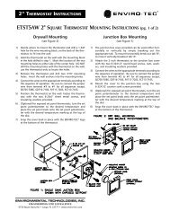
2” THERMOSTAT INSTRUCTIONSAppendix AETST4H 2" SQUARE THERMOSTAT MOUNTING INSTRUCTIONSDrywall Mounting(see Figure 2)1) Decide where to mount the thermostat and drill a 1-3/8"hole for the wire mounting block, on the back of the thermostat,to fit into the wall.2) Hold the thermostat on the wall with the mounting blockin the hole drilled in step 1. Mark the location of the twomounting holes to either side of the center hole. DO NOTdrill the mounting holes with the thermostat on the wall,use the thermostat only to locate the holes.3) Remove the thermostat and drill two 3/16" mountingholes. Insert the wall anchors into the mounting holes.4) Connect the wires to the appropriate terminals accordingto the sequence of operation.5) Position the thermostat on the wall. Fasten the thermostatwith the two 6-20x1" sheet metal screws andinsulating washers provided.6) (Optional) For exposed set point stats, turn the set pointpotentiometer to the desired temperature and place theset point knob onto the set point potentiometer with thedesired temperature marking at the top of the dial.7) Snap the cover back in place with the ENVIRO-TEC ® logoat the bottom of the thermostat.Junction Box Mounting(see Figure 1)1) The junction box cover provided can be used either horizontallyor vertically by simply breaking out theappropriate tab. To mount horizontally break out tab "B",to mount vertically breakout tab "A".2) Attach the 2 inch thermostat to the junction box coverwith the two 6-32X1/2" round head screws, nuts, washers,and insulating washers provided.3) Connect the wires to the appropriate terminals accordingto the sequence of operation.4) Mount the cover to the junction box using the two 6-32X1/2" counter sunk screws provided.5) (Optional) For exposed set point stats, turn the set pointpotentiometer to the desired temperature and place theset point knob onto the set point potentiometer with thedesired temperature marking at the top of the dial.6) Snap the cover back in place with the ENVIRO-TEC ® logoat the bottom of the thermostat.NOTE: The temperature setpoint adjustment on the ETST4H thermostat is reversed from the older (ETSTAT)series thermostats. When using the 600 Series <strong>IOM</strong> manual in conjunction with the ETST4H, the directionof rotation of this setpoint should be reversed from the direction stated in manual's instructions.