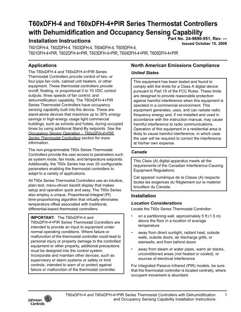
T60xDFH-4 and T60xDFH-4+PIR Series Thermostat ... - Enviro-Tec
T60xDFH-4 and T60xDFH-4+PIR Series Thermostat ... - Enviro-Tec
T60xDFH-4 and T60xDFH-4+PIR Series Thermostat ... - Enviro-Tec

Create successful ePaper yourself
Turn your PDF publications into a flip-book with our unique Google optimized e-Paper software.
Table 1: Terminal Identification (See Figure 5.)TerminalNumberT601DFH-4,T601DFH-<strong>4+PIR</strong>(On/Off Control)Terminal LabelT602DFH-4,T602DFH-<strong>4+PIR</strong>,T603DFH-4,T603DFH-<strong>4+PIR</strong>(On/Off orFloating Control)T604DFH-4,T604DFH-<strong>4+PIR</strong>,T605DFH-4,T605DFH-<strong>4+PIR</strong>(Proportional 0 to10 VDC Control)Function1 Fan-H Fan-H Fan-H Fan On – High2 Fan-M Fan-M Fan-M Fan On – Medium3 Fan-L Fan-L Fan-L Fan On – Low4 24 V~ Hot 24 V~ Hot 24 V~ Hot 24 VAC from Transformer5 24 V~ Com 24 V~ Com 24 V~ Com 24 VAC (Common) from Transformer6 BO5 Aux BO5 Aux BO5 Aux Aux BO (Auxiliary Output)7 BO5 Aux BO5 Aux BO5 Aux Aux BO (Auxiliary Output)8 BO3 BO3 Blank Open Heat9 Blank BO4 AO2 Close Heat10 Blank BO1 AO1 Open Cool11 BO2 BO2 Blank Close Cool12 BI1 BI1 BI1 Configurable Binary Input 113 RS RS RS Remote Room Temperature Sensor14 Scom Scom Scom Sensor Common15 BI2 BI2 BI2 Configurable Binary Input 216 UI3 UI3 UI3 Configurable Universal Input 34<strong>T60xDFH</strong>-4 <strong>and</strong> <strong>T60xDFH</strong>-<strong>4+PIR</strong> <strong>Series</strong> <strong>Thermostat</strong> Controllers with Dehumidification <strong>and</strong> OccupancySensing Capability Installation Instructions
24 V~Hot24 V~ComPower <strong>and</strong> FanFan-LFan-MFan-HSeparate 24 VACPower Source for Auxiliary Output(24 VAC Maximum)BO5AuxBO5AuxAuxFive-PoleLeft Top ConnectorFan-HFan-MFan-L24 V~Hot24 V~Com1 2 3 4 5Three-PoleRight TopConnectorBO5AuxBO5AuxBO36 7 8Eight-Pole Bottom ConnectorBO4/AO2BO1/AO1BO2BI1RSScomBI2UI39 10 11 12 13 14 15 1624 VAC<strong>Thermostat</strong> ControllerPower24 V~Hot24 V~ComPower <strong>and</strong> FanFan-LFan-M- OR -Fan-HSame 24 VACPower Source for Auxiliary Output(24 VAC Maximum)BO5AuxBO5AuxAuxIndependentContacts• Reheat• Lighting• On/Off Actuation• Exhaust FanBI1Voltage-FreeContact• Remote NSB• Motion• WindowRemote InputsScomBI2- OR -UI3Supply SensorChangeover SensorVoltage-FreeContact• Door• RemoteOverride• Filter Alarm• Service AlarmVoltage-FreeContact• COC/NHNormally HeatClosed Contact= Cold Water• COC/NCNormally CoolClosed Contact= Hot Water24 VAC<strong>Thermostat</strong> ControllerPowerFIG:wrngFigure 5: Wiring the <strong>T60xDFH</strong>-4 or <strong>T60xDFH</strong>-<strong>4+PIR</strong> <strong>Series</strong> <strong>Thermostat</strong> Controller(See Table 1.)<strong>T60xDFH</strong>-4 <strong>and</strong> <strong>T60xDFH</strong>-<strong>4+PIR</strong> <strong>Series</strong> <strong>Thermostat</strong> Controllers with Dehumidification <strong>and</strong> OccupancySensing Capability Installation Instructions5
BO224 V~Hot24 V~ComN.C.CoolingValveBO324 V~Hot24 V~ComTwo-Pipe ApplicationsN.O.HeatingValveFour-Pipe ApplicationsFigure 6: Wiring T601DFH-4 <strong>Thermostat</strong> Controllers for On/Off ControlFIG:T601dfh3oocor24 V~Hot24 V~ComCoolingValveoror24 V~Hot24 V~ComHeatingValveFIG:T6023dfh3oocTwo-Pipe ApplicationsFour-Pipe ApplicationsFigure 7: Wiring T602DFH-4 <strong>and</strong> T603DFH-4 <strong>Thermostat</strong> Controllers for On/Off ControlBO1BO224 V~Hot24 V~ComCoolingValveBO1BO2 BO3 BO424 V~Hot24 V~ComHeating/CoolingValveTwo-Pipe ApplicationsHeatingValveFour-Pipe ApplicationsFigure 8: Wiring T602DFH-4 <strong>and</strong> T603DFH-4 <strong>Thermostat</strong> Controllers for Floating ControlFIG:T6023dfh3fcAO124 V~Hot24 V~ComAO1AO224 V~Hot24 V~ComCoolingValveHeating/CoolingValveHeatingValveFIG:T6045dfh3prpTwo-Pipe ApplicationsFour-Pipe ApplicationsFigure 9: Wiring T604DFH-4 <strong>and</strong> T605DFH-4 <strong>Thermostat</strong> Controllers for Proportional Control6<strong>T60xDFH</strong>-4 <strong>and</strong> <strong>T60xDFH</strong>-<strong>4+PIR</strong> <strong>Series</strong> <strong>Thermostat</strong> Controllers with Dehumidification <strong>and</strong> OccupancySensing Capability Installation Instructions
Setup <strong>and</strong> Adjustments<strong>Thermostat</strong> Controller Operation OverviewPIR motion detectorsaves energy usingst<strong>and</strong>-by setpoints.Backlit, plain textLiquid Crystal Display (LCD)is easy to read in any condition.Room Temp70.0ºF°C°FLight-Emitting Diodes (LEDs)indicate system activity.Five keys on the thermostat controllermake operation easy <strong>and</strong> intuitive.FIG:frnt_vwFigure 10: Front Cover of <strong>Thermostat</strong> Controller (<strong>T60xDFH</strong>-<strong>4+PIR</strong> Model Shown)<strong>Thermostat</strong> Controller User Interface KeysThe T60x <strong>Series</strong> <strong>Thermostat</strong> Controller user interfaceconsists of five keys on the front cover (as illustrated inFigure 10). The function of each key is as follows:• Use the MODE key to toggle among the systemmodes available, as defined by selecting theappropriate operation sequence in the InstallerConfiguration Menu (for example, Off, Heat, Cool,Auto).• Use the FAN key to toggle among the fan modesavailable, as defined by selecting the appropriatefan menu options defined in the InstallerConfiguration Menu (for example, Low, Med, High,Auto).• Use the °C/°F key to change the temperature scaleto either Celsius or Fahrenheit <strong>and</strong> allow access tothe Installer Configuration Menu. See theConfiguring the <strong>T60xDFH</strong>-4 <strong>and</strong><strong>T60xDFH</strong>-<strong>4+PIR</strong> <strong>Series</strong> <strong>Thermostat</strong> Controllersection.• Use the UP/DOWN arrow keys to change theconfiguration parameters <strong>and</strong> to activate a setpointadjustment.Backlit LCDThe T60x <strong>Series</strong> <strong>Thermostat</strong> Controllers include a2-line, 8-character backlit display. Low-levelbacklighting is present during normal operation, <strong>and</strong> itbrightens when any user interface key is pressed. Thebacklight returns to low level when the thermostatcontroller is left unattended for 45 seconds.LEDsThree LEDs are included to indicate the fan status, callfor heat, or call for cooling:• The fan LED is on when the fan is on.• The heat LED is on when heating is on.• The cool LED is on when cooling is on.Integrated PIR Sensor –<strong>T60xDFH</strong>-<strong>4+PIR</strong> <strong>Series</strong> <strong>Thermostat</strong> ControllersThe integrated PIR sensor allows for automaticswitching between fully adjustable Occupied <strong>and</strong>St<strong>and</strong>-By temperature setpoints without userinteraction. This feature generates incremental energysavings during scheduled occupied periods while thespace is unoccupied.<strong>T60xDFH</strong>-4 <strong>and</strong> <strong>T60xDFH</strong>-<strong>4+PIR</strong> <strong>Series</strong> <strong>Thermostat</strong> Controllers with Dehumidification <strong>and</strong> OccupancySensing Capability Installation Instructions7
Status Display MenuThe Status Display Menu is displayed during normalthermostat controller operation. This menucontinuously scrolls through the following parameters:• Room Temperature (All Models) <strong>and</strong> Humidity(T603DFH-4 <strong>and</strong> T605DFH-4 Models)Note: For models with dehumidification capability, thedefault setting is no humidity reading on the display(%RH disp parameter is set to off). The %RH dispparameter must be set to on to display the currenthumidity reading.• System Mode• Schedule Status(Occupied/Unoccupied/Override/St<strong>and</strong>-By[PIR Models])• Applicable Alarms – The backlight lights up as analarm condition is displayed.Note: An option is available within the InstallerConfiguration Menu to lock out the scrolling display <strong>and</strong>show only the Room Temperature parameter.Dehumidification Operation – T603DFH-4 <strong>and</strong>T605DFH-4 <strong>Thermostat</strong> Controller ModelsDehumidification activates when the room humidity isabove the adjustable humidity setpoint as sensed bythe integral humidity sensor.Note: Dehumidification operation functions only in theCooling mode; dehumidification operation does notfunction in either the Off or the Heating mode.The minimum deadb<strong>and</strong> between the Heating <strong>and</strong>Cooling setpoints is adjustable from 2.0F°/1.0C° to5.0F°/2.5C°, as defined by the Deadb<strong>and</strong> parameter inTable 4. If the room temperature resides in thedeadb<strong>and</strong> between the Heating <strong>and</strong> Cooling setpoints:• the thermostat controller forces the fan to lowspeed• the chilled water valve opens to the specifiedmaximum value set by CoolMax• the thermostat controller stages Heating tomaintain the room temperature at the Coolingsetpoint, as sensed by the thermostat controllerIf the room temperature falls below the result of theformula 1 + Cooling Setpoint – Deadb<strong>and</strong>, then thethermostat controller disables dehumidificationoperation.If the thermostat controller is in Cooling dem<strong>and</strong>:• the chilled water valve opens to 100%• the thermostat controller stages Heating tomaintain the room temperature at the Coolingsetpoint, as sensed by the thermostat controllerIf the thermostat controller is in Cooling dem<strong>and</strong> <strong>and</strong>the room temperature rises 2F°/1C° above the Coolingsetpoint, the thermostat controller automaticallydisables dehumidification operation. Likewise, if thethermostat controller is in Cooling dem<strong>and</strong> <strong>and</strong> theroom temperature falls below the current Heatingsetpoint, the thermostat controller disablesdehumidification operation.Occupancy Sensor Operation –<strong>T60xDFH</strong>-<strong>4+PIR</strong> <strong>Series</strong> <strong>Thermostat</strong> ControllersA <strong>T60xDFH</strong>-<strong>4+PIR</strong> <strong>Series</strong> <strong>Thermostat</strong> Controller (or a<strong>T60xDFH</strong>-4 <strong>Series</strong> <strong>Thermostat</strong> Controller equippedwith a PIR accessory cover) provides advancedoccupancy logic.Note: The PIR strategy is an occupied strategy. If thethermostat controller is programmed to be Unoccupied,the PIR function does not have an effect on theoccupancy strategy.The thermostat controller automatically switchesoccupancy levels from Occupied to St<strong>and</strong>-By <strong>and</strong>Unoccupied as required, when local movement issensed.Occupancy sensing is enabled only if a PIR cover isinstalled on the thermostat controller (PIR models) or ifa remote input is configured as a remote PIR sensor(MotionNO or MotionNC).PIR Warm-Up PeriodWhen a PIR cover is used <strong>and</strong> a thermostat controlleris powered up, there is a 1-minute warm-up periodbefore any local movement can be detected <strong>and</strong>acknowledged by the PIR sensing device. The localstatus LEDs for the PIR function are not active, <strong>and</strong> thesensor is in St<strong>and</strong>-By mode for the 1-minute period.The PIR functionality <strong>and</strong> local movement status LEDsare activated after the 1-minute warm-up period haselapsed after the initial powering of the thermostatcontroller. If movement is present, the mode changesto Occupied.PIR Diagnostic LEDsThe diagnostic LEDs inside the PIR lens brighten whenmovement is detected within the first 30 minutes afterpowerup. The LEDs do not light up or brighten after theinitial 30-minute period.8<strong>T60xDFH</strong>-4 <strong>and</strong> <strong>T60xDFH</strong>-<strong>4+PIR</strong> <strong>Series</strong> <strong>Thermostat</strong> Controllers with Dehumidification <strong>and</strong> OccupancySensing Capability Installation Instructions
SetpointsThe St<strong>and</strong>-By setpoints are under the same limitations<strong>and</strong> restrictions as the Occupied <strong>and</strong> Unoccupiedsetpoints. St<strong>and</strong>-By setpoints reside between thecorresponding Occupied <strong>and</strong> Unoccupied setpointvalues.The installer must be certain that the differencebetween the St<strong>and</strong>-By <strong>and</strong> Occupied values can berecovered within a timely fashion to ensure occupancycomfort. In addition, the difference between the twovalues must be large enough to warrant maximumenergy savings.Unocc Heat= 65°FSt-By Heat= 69°FOcc Heat= 72°FOcc Cool= 75°FSt-By Cool= 78°FRoom TemperatureFIG:rm_tmpFigure 11: Increasing Room Temperature SetpointsHotel <strong>and</strong> lodging applications can benefit from theaddition of an entry door switch wired to one of thebinary inputs of the thermostat controller. When a doorcontact is used <strong>and</strong> configured, the St<strong>and</strong>-By timer <strong>and</strong>its configuration are no longer active or used. Theoccupancy toggle between Occupied <strong>and</strong> St<strong>and</strong>-By isthen dictated by both the door contact <strong>and</strong> thePIR sensing device used. If movements are detectedby the PIR sensor <strong>and</strong> the door is closed, the room isconsidered occupied. The thermostat controllerswitches back to St<strong>and</strong>-By mode only if the door switchtoggles open/closed. Motion is ignored when the doorswitch indicates an open door.PIR occupancy functionality is dictated by both theSt<strong>and</strong>-By timer <strong>and</strong> Unoccupied timer configurationvalue <strong>and</strong> movements present in the area.Unoccupied Timer DisableIt might be preferable for the local area to stay out ofUnoccupied mode <strong>and</strong> always stay at the St<strong>and</strong>-Byoccupancy level when no activity is present. Ininstances when areas always need to be on St<strong>and</strong>-Bystatus, ready to respond to dem<strong>and</strong> at any given pointin time, we recommend disabling the Unoccupied timer.When the local PIR occupancy routine is running at thethermostat controller, the zone drifts into Unoccupiedmode when the Unoccupied timer is set above itsfactory default value of 0.0 hours.OccupiedSt<strong>and</strong>-By= 2 HoursSt<strong>and</strong>-By= 2 HrsSt<strong>and</strong>-ByUnoccupiedUnoccupied Time= 6 HoursUnoccupied Time= 6 HoursFirst MovementDetected by PIR DeviceLast Movement Detectedby PIR DeviceTimeSt<strong>and</strong>-By Time Elapsed= St<strong>and</strong>-By ModeUnoccupied Time Elapsed= Unoccupied ModeFirst MovementDetectedby PIR DeviceLast Movement Detectedby PIR DeviceTimeSt<strong>and</strong>-By Time Elapsed= St<strong>and</strong>-By ModeFIG:unocc6sb2Figure 12: Unoccupied Timer Set to 6 Hours <strong>and</strong> St<strong>and</strong>-By Timer Set to 2 Hours<strong>T60xDFH</strong>-4 <strong>and</strong> <strong>T60xDFH</strong>-<strong>4+PIR</strong> <strong>Series</strong> <strong>Thermostat</strong> Controllers with Dehumidification <strong>and</strong> OccupancySensing Capability Installation Instructions9
OccupiedSt<strong>and</strong>-By= 2 HrsSt<strong>and</strong>-By= 2 HrsSt<strong>and</strong>-ByUnoccupiedUnoccupied Time= 0 HoursUnoccupied Time= 0 HoursFirst Movement Detectedby PIR DeviceLast Movement Detectedby PIR DeviceSt<strong>and</strong>-By Time Elapsed= St<strong>and</strong>-By ModeTimeFirst Movement Detectedby PIR DeviceLast Movement Detectedby PIR DeviceTimeSt<strong>and</strong>-By Time Elapsed= St<strong>and</strong>-By ModeFIG:unocc0sb2Figure 13: Unoccupied Timer Set to 0 Hours <strong>and</strong> St<strong>and</strong>-By Timer Set to 2 HoursWhen the local PIR occupancy routine is running at thethermostat controller, the zone never drifts intoUnoccupied mode when the Unoccupied timer is set toits factory default value of 0.0 hours.Refer to the <strong>T60xDFH</strong>-4 <strong>and</strong> <strong>T60xDFH</strong>-<strong>4+PIR</strong> <strong>Series</strong><strong>Thermostat</strong> Controllers with Dehumidification <strong>and</strong>Occupancy Sensing Capability Application Note(LIT-12011569) for additional application scenariosusing various combinations of occupancy levels <strong>and</strong>door switches.Configuring the <strong>T60xDFH</strong>-4 <strong>and</strong><strong>T60xDFH</strong>-<strong>4+PIR</strong> <strong>Series</strong> <strong>Thermostat</strong> ControllerThe T60x <strong>Series</strong> <strong>Thermostat</strong> Controller comes from thefactory with default settings for all configurableparameters. The default settings are shown in Table 4.To reconfigure the parameters via the thermostatcontroller, follow the steps in this section.1. To access the Installer Configuration Menu, press<strong>and</strong> hold the center key for approximately8 seconds.Note: If the Password parameter is configured,Password 0 appears on the thermostat controllerdisplay indicating that the configured password isrequired to proceed. Use the UP/DOWN arrow keys toindicate the configured password, then press theMODE key to proceed through the InstallerConfiguration Menu parameters.2. Once the Installer Configuration Menu begins,press <strong>and</strong> release the center key to scroll throughthe parameters listed in Table 4.3. When the desired parameter is displayed, use theUP/DOWN arrow keys to choose the desiredselection option.4. Press <strong>and</strong> release the center key to continuescrolling through the parameters.Note: Pressing the FAN key during configurationrestarts the list of displayed parameters at the firstparameter listed in Table 4.When the thermostat controller is in the InstallerConfiguration Menu <strong>and</strong> left unattended forapproximately 8 seconds, the thermostat controllerreverts to the Status Display Menu.Configuring Inputs BI1, BI2, <strong>and</strong> UI3When BI1 <strong>and</strong> BI2 are configured for an alarmcondition, an alarm condition is displayed locally whenthe input is closed. An alarm message is included onthe scrolling Status Display Menu <strong>and</strong> when themessage is displayed, the backlight momentarilylights up.The UI3 input provides changeover of hot/cold waterswitching or supply air temperature monitoring at thethermostat controller.Each input can be configured to the selection optionsincluded in Table 4.Configuring the Sequence of Operation(SeqOpera)Choose the appropriate sequence of operation usingTable 2 or Table 3. The modes presented areuser-dependent on the sequence of operationselected. For two-pipe applications using a changeoversensor, choose the selection option (0): Cooling Only.Changeover occurs between Cooling Only <strong>and</strong>Heating Only. See Figure 14 through Figure 19 forsequence of operation examples.10<strong>T60xDFH</strong>-4 <strong>and</strong> <strong>T60xDFH</strong>-<strong>4+PIR</strong> <strong>Series</strong> <strong>Thermostat</strong> Controllers with Dehumidification <strong>and</strong> OccupancySensing Capability Installation Instructions
Table 2: Selection Options for Sequence of Operation in Two-Pipe ApplicationsSelectionOptionControlCurve(0): Cooling Only See Figure 14. 10: Normally Open(N.O.) Cooling11: Normally Closed(N.C.) Cooling(1): Heating Only See Figure 15. 10: N.O. Heating11: N.C. Heating(2): Cooling <strong>and</strong> Reheat See Figure 16. 6 <strong>and</strong> 7: Reheat10: N.O. Cooling11: N.C. Cooling(3): Heating <strong>and</strong> Reheat See Figure 17. 6 <strong>and</strong> 7: Reheat10: N.O. Heating11: N.C. HeatingTerminal Numbers Used (See Table 1 <strong>and</strong> Figure 5.)On/Off Control Floating Control Proportional0to10VDC Control10: Open Cooling11: Closed Cooling10: Open Heating11: Closed Heating6 <strong>and</strong> 7: Reheat10: Open Cooling11: Closed Cooling6 <strong>and</strong> 7: Reheat10: Open Heating11: Closed HeatingTable 3: Selection Options for Sequence of Operation in Four-Pipe ApplicationsSelectionOptionControlCurve(0): Cooling Only See Figure 14. 10: N.O. Cooling11: N.C. Cooling(1): Heating Only See Figure 15. 8: N.O. Heating9: N.C. Heating(2): Cooling <strong>and</strong> Reheat See Figure 16. 6 <strong>and</strong> 7: Reheat10: N.O. Cooling11: N.C. Cooling(3): Heating <strong>and</strong> Reheat See Figure 17. 6 <strong>and</strong> 7: Reheat8: N.O. Heating9: N.C. Heating(4): Cool/Heat Four-Pipe See Figure 18. 8: N.O. Heating9: N.C. Heating10: N.O. Cooling11: N.C. Cooling(5): Cool/Heat Four-Pipe<strong>and</strong> ReheatSee Figure 19.10: Proportional Cooling10: Proportional Heating6 <strong>and</strong> 7: Reheat10: Proportional Cooling6 <strong>and</strong> 7: Reheat10: Proportional HeatingTerminal Numbers Used (See Table 1 <strong>and</strong> Figure 5.)On/Off Control Floating Control Proportional0to10VDC Control6 <strong>and</strong> 7: Reheat8: N.O. Heating9: N.C. Heating10: N.O. Cooling11: N.C. Cooling10: Open Cooling11: Closed Cooling8: Open Heating9: Closed Heating6 <strong>and</strong> 7: Reheat10: Open Cooling11: Closed Cooling6 <strong>and</strong> 7: Reheat8: Open Heating9: Closed Heating8: Open Heating9: Closed Heating10: Open Cooling11: Closed Cooling6 <strong>and</strong> 7: Reheat8: Open Heating9: Closed Heating10: Open Cooling11: Closed Cooling10: Proportional Cooling9: Proportional Heating6 <strong>and</strong> 7: Reheat10: Proportional Cooling6 <strong>and</strong> 7: Reheat9: Proportional Heating9: Proportional Heating10: Proportional Cooling6 <strong>and</strong> 7: Reheat9: Proportional Heating10: Proportional Cooling<strong>T60xDFH</strong>-4 <strong>and</strong> <strong>T60xDFH</strong>-<strong>4+PIR</strong> <strong>Series</strong> <strong>Thermostat</strong> Controllers with Dehumidification <strong>and</strong> OccupancySensing Capability Installation Instructions11
Cooling SetpointOnDevice OpenedOnReheatOffDevice ClosedOn/Off, Floating,or ProportionalOutputOff100%Temperature Increase(Increments of 1F°/0.5C°)Figure 14: Cooling Only,Two- or Four-Pipe ApplicationsFIG:clng_nlyOn/Off, Floating,or ProportionalOutput0%Device OpenedOn/Off, Floating,or ProportionalOutputHeating SetpointDevice ClosedTemperature Increase(Increments of 1F°/0.5C°)Figure 15: Heating Only,Two- or Four-Pipe ApplicationsHeating OutputFIG:htng_nlyDeviceOpenedTemperature Increase(Increments of 1F°/0.5C°)Figure 17: Heating with Reheat,Two- or Four-Pipe ApplicationsHeating SetpointDeadb<strong>and</strong>Heating OutputCooling OutputCooling SetpointFIG:htg_wth_rhtDeviceOpenedHeating SetpointCooling OutputCooling SetpointDeviceClosedDeviceClosedOn/Off, Floating, orProportional OutputsOnDeadb<strong>and</strong>DeviceOpenedTemperature Increase(Increments of 1F°/0.5C°)FIG:htng_clngOnReheatOffOffDeviceClosedOn/Off, Floating,or ProportionalOutputsFigure 18: Heating/Cooling,Four-Pipe ApplicationsTemperature Increase(Increments of 1F°/0.5C°)FIG:clng_wth_rhtFigure 16: Cooling with Reheat,Two- or Four-Pipe Applications12<strong>T60xDFH</strong>-4 <strong>and</strong> <strong>T60xDFH</strong>-<strong>4+PIR</strong> <strong>Series</strong> <strong>Thermostat</strong> Controllers with Dehumidification <strong>and</strong> OccupancySensing Capability Installation Instructions
On/Off, Floating,or ProportionalOutputsHeating OutputCooling OutputOnHeating SetpointCooling SetpointOnReheatOutputOffOffDeviceOpenedDeadb<strong>and</strong>DeviceOpenedDeviceClosedDeviceClosedTemperature Increase(Increments of 1F°/0.5C°)FIG:htng_clng_rhtConfiguring Automatic Fan SpeedUse the Fan Menu parameter in the InstallerConfiguration Menu to set the available fan modeoptions. Use the FAN key to select the desired fanmode option.Figure 19: Heating/Cooling with Reheat,Four-Pipe ApplicationsWhen selection option (2): Low-Med-High-Auto ischosen in the Fan Menu parameter, the fan operatesas shown in Figure 20. When selection option(3): Low-High-Auto is chosen in the Fan Menuparameter, the fan operates at only the low <strong>and</strong> highsettings <strong>and</strong> ignores the medium setting (Figure 20).This operation applies to the Occupied mode when thefan is set to Auto.FanSpeedHighMediumOnOffLowOnOffHeatingSetpointThe fan is offbetween theheating <strong>and</strong>cooling setpointsif the Auto Fanparameter isset to AS AD.CoolingSetpointOffOnOffOn100%HeatingValve2.0F°/1.0C° to5.0F°/2.5C°Deadb<strong>and</strong>CoolingValve0%FIG:fn_oprtn2.5 2.0 1.5 0.5 0.51.5 2.0 2.5Temperature Deviation from Setpoint, °FFigure 20: Low-Med-High-Auto <strong>and</strong> Low-High-Auto Fan Operation<strong>T60xDFH</strong>-4 <strong>and</strong> <strong>T60xDFH</strong>-<strong>4+PIR</strong> <strong>Series</strong> <strong>Thermostat</strong> Controllers with Dehumidification <strong>and</strong> OccupancySensing Capability Installation Instructions13
Table 4: Installer Configuration Menu (Part 1 of 7)ParameterAppearingon DisplayDescription <strong>and</strong> Default Selection OptionsPswrdSets the protective accesspassword to prevent unauthorizedaccess to the Installer ConfigurationMenu.Default: 0Note: The default setting does notlock out access to the InstallerConfiguration Menu.BI1 Configuration of Binary Input 1.Default: NoneRange: 0 to 1,000(None): No function is associated with an input.(Rem NSB): Remote Night Setback (NSB) via a time clock input, anoccupancy sensor, or from a voltage-free contact.Contact open = Occupied; contact closed = Unoccupied.(MotionNO*): Temporary occupancy request via a motion detectorinput. Contact open = Unoccupied. When the contact closes, thethermostat controller goes into the Occupied mode for a specifiedTOccTime. Once the TOccTime begins, the thermostat controllerremains in the Occupied mode if the contact is open, until theTOccTime expires. Advanced PIR occupancy functions using aNormally Open (N.O.) or Normally Closed (N.C.) remote PIR motionsensor.(MotionNC*): Temporary occupancy request via a motion detectorinput. Contact closed = Unoccupied. When the contact opens, thethermostat controller goes into the Occupied mode for a specifiedTOccTime. Once the TOccTime begins, the thermostat controllerremains in the Occupied mode if the contact is closed, until theTOccTime expires. Advanced PIR occupancy functions using aNormally Open (N.O.) or Normally Closed (N.C.) remote PIR motionsensor.(Window): Cancels the thermostat controller heating or coolingaction when a window is open. The fan operation is only affected ifthe Fan Menu parameter is set to (4): On-Auto, <strong>and</strong> Auto is theselected fan mode. A Window alarm is displayed indicating that thewindow needs to be closed to resume heating or cooling. Theheating <strong>and</strong>/or cooling outputs are enabled only when the contact isclosed.* These settings disable any local override function. For PIRmodels, see the Occupancy Sensor Operation – <strong>T60xDFH</strong>-<strong>4+PIR</strong><strong>Series</strong> <strong>Thermostat</strong> Controllers section.14<strong>T60xDFH</strong>-4 <strong>and</strong> <strong>T60xDFH</strong>-<strong>4+PIR</strong> <strong>Series</strong> <strong>Thermostat</strong> Controllers with Dehumidification <strong>and</strong> OccupancySensing Capability Installation Instructions
Table 4: Installer Configuration Menu (Part 2 of 7)ParameterAppearingon DisplayDescription <strong>and</strong> Default Selection OptionsBI2 Configuration of Binary Input 2.Default: NoneUI3 Configuration of Universal Input 3.Default: NoneMenuScroAutoMode%RH dispGives the option of having thedisplay continuously scroll theparameters.Default: onEnables the auto function (ifOption 2 is chosen in the SeqOperaparameter) to be visible within theMODE key menu. (The MODE keyis the key at the far left of thethermostat controller cover.)Default: offDisplays the current humidityreading (T603 <strong>and</strong> T605 models).Default: off(None): No function is associated with an input.(Door Dry): Door contact only has an effect if BI1 is set toMotionNO or MotionNC or if a PIR accessory cover is used. (Seethe BI1 parameter earlier in this table.) The occupancy is nowdictated via BI1, BI2, or PIR. Any motion detected sets the zone toOccupied status. The thermostat controller remains in the Occupiedmode until the door contact switch opens momentarily, at whichpoint the thermostat controller goes into St<strong>and</strong>-By mode. If moremovements are detected, the Occupied mode resumes. While thedoor is open, any movements detected by the PIR sensor areignored. Use a Normally Closed (N.C.) switching device. (Contactopen = door open; contact closed = door closed.)(RemOVR): Temporary occupancy request via a remote input. Thisoverride function is controlled by a manual remote occupancyoverride. When enabled, this condition disables the overridecapability of the thermostat controller.(Filter): A Filter alarm is displayed. This alarm can be connected toa differential pressure switch that monitors a filter.(Service): A Service alarm is displayed on the thermostat controllerwhen the input is energized. This input can be tied into the airconditioning unit control card, which provides an alarm should therebe a malfunction.(None): No function is associated with an input.(COC/NH): Changeover Contact/Normally Heat: A dry contact inputis used to signal seasonal hot/cold water changeover. The contactcloses when cold water is present. Valid only for two-pipe systems.(COC/NC): Changeover Contact/Normally Cool: A dry contact inputis used to signal seasonal hot/cold water changeover. The contactcloses when hot water is present. Valid only for two-pipe systems.(COS): Changeover Analog Sensor: Used for hot/cold waterchangeover switching. Valid only for two-pipe systems. (ParameterPipe No is set to 2.0.) If the water temperature is greater than75°F/24°C, hot water is present. If the water temperature is lessthan 75°F/24°C, cold water is present.Note: Choose the selection option (0): Cooling Only for theSeqOpera parameter to allow changeover to occur betweenCooling Only <strong>and</strong> Heating Only. The changeover sensor does notoperate in Cooling <strong>and</strong> Reheat, Heating <strong>and</strong> Reheat, orCool/Heat Four-Pipe <strong>and</strong> Reheat applications.(SS): Supply Air Sensor Monitoring(off): The scroll is inactive.(on): The scroll is active.(on): The auto function is active (Off-Auto-Heat-Cool). Providesautomatic changeover between heating <strong>and</strong> cooling.(off): The auto function is inactive (Off-Heat-Cool).(on): Displays the current humidity reading in % RH.(off): Does not display the current humidity reading.<strong>T60xDFH</strong>-4 <strong>and</strong> <strong>T60xDFH</strong>-<strong>4+PIR</strong> <strong>Series</strong> <strong>Thermostat</strong> Controllers with Dehumidification <strong>and</strong> OccupancySensing Capability Installation Instructions15
Table 4: Installer Configuration Menu (Part 3 of 7)ParameterAppearingon DisplayDescription <strong>and</strong> Default Selection OptionsLockoutPipe NoCntrlTypSeqOperaFan MenuDHumiLCKSelectable Lockout Levels forlimiting end-user keypad interaction.Default: 0Selectable number of pipes in thesystem.Default: 4.0 PipesDefines the control output for thetype of valves used in theinstallation (T602 <strong>and</strong> T603models).Default: FloatingDetermines the sequence ofoperation.Default: 1Sets the fan mode options.Default: 4Locks out the dehumidificationcapability (T603 <strong>and</strong> T605 models).Default: onLockoutLevelModeSettingFanSettingFunctionLocalOverrideOccupiedTemperatureSetpoints(0) Access Access Access Access(1) Access Access No Access Access(2) No Access No Access Access Access(3) No Access No Access No Access Access(4) No Access No Access Access No Access(5) No Access No Access No Access No Access(2.0 Pipes): Limits the number of sequences of operation availablefrom 0 to 3, <strong>and</strong> enables heat/cool operation from the same output.(4.0 Pipes): Allows access to all sequences of operation from 0 to 5,<strong>and</strong> enables heat/cool operation from different outputs.(On/Off): For Normally Open (N.O.) or Normally Closed (N.C.)24 VAC two-position valves.(Floating): For three-wire control of 24 VAC floating valves.Sequence of OperationDefault Based onAutoMode ParameterSettingOnOff(0): Cooling Only (Off-Cool) Cool Cool(1): Heating Only (Off-Heat) Heat Heat(2): Cooling <strong>and</strong> ReheatAuto Heat(Off-Auto*-Heat-Cool)(3): Heating <strong>and</strong> Reheat (Off-Heat) Heat Heat(4):Cool/Heat Four-PipeAuto Heat(Off-Auto*-Heat-Cool)(5): Cool/Heat Four-Pipe <strong>and</strong> Reheat Auto Heat(Off-Auto*-Heat-Cool)* Auto can be disabled with the AutoMode parameter.Note: Choose the selection option (0): Cooling Only when using achangeover sensor to allow changeover to occur between CoolingOnly <strong>and</strong> Heating Only.(0): Low-Med-High: Three-speed configuration using three fanrelays (L-M-H). The default is High.(1): Low-High: Two-speed configuration using two fan relays (L-H).The default is High.(2): Low-Med-High-Auto: Three-speed configuration with Auto Fanspeed mode using three fan relays (L-M-H). The default is High.(3): Low-High-Auto: Two-speed configuration with Auto Fan speedmode using two fan relays (L-H). The default is High.(4): On-Auto: One-speed configuration, (H) Auto is for Fan ondem<strong>and</strong> <strong>and</strong> On is for Fan on all the time. The default is Auto.(off): Dehumidification is locked out.(on): Dehumidification is allowed.16<strong>T60xDFH</strong>-4 <strong>and</strong> <strong>T60xDFH</strong>-<strong>4+PIR</strong> <strong>Series</strong> <strong>Thermostat</strong> Controllers with Dehumidification <strong>and</strong> OccupancySensing Capability Installation Instructions
Table 4: Installer Configuration Menu (Part 4 of 7)ParameterAppearingon DisplayDescription <strong>and</strong> Default Selection Options%RH set 1DehuHyst 1DehuCool 1St-By TMUnocc TMSt-By HTSt-By CLUnocc HTUnocc CLHeat maxCool minSets the dehumidification setpoints(T603 <strong>and</strong> T605 models). Thisparameter can be used only if thedehumidification sequence isenabled.Default: 50.0% RHSets the dehumidification hysteresis(T603 <strong>and</strong> T605 models). Thisparameter can be used only if thedehumidification sequence isenabled.Default: 5.0% RHSets the maximum dehumidificationcooling output (T603 <strong>and</strong> T605models). This parameter can beused only if the dehumidificationsequence is enabled.Default: 100%Sets the St<strong>and</strong>-By timer value(PIR models).Default: 0.5 hoursSets the Unoccupied timer value(PIR models).Default: 0.0 hoursSets the St<strong>and</strong>-By heating setpoint(PIR models).Default: 69.0°F/20.5°CSets the St<strong>and</strong>-By cooling setpoint(PIR models).Default: 78.0°F/25.5°CSets the Unoccupied heatingsetpoint value.Default: 62.0°F/16.5°CSets the Unoccupied coolingsetpoint value.Default: 80.0°F/26.5°CSets the Occupied <strong>and</strong> Unoccupiedmaximum heating setpoint values.Default: 90.0°F/32.0°CSets the Occupied <strong>and</strong> Unoccupiedminimum cooling setpoint values.Default: 54.0°F/12.0°CRange: 30.0 to 95.0% RHRange: 2.0 to 20.0% RHRange: 20.0 to 100.0%Note: This parameter can be used to balance smaller reheat loadsinstalled with regard to the capacity of the cooling coil.Time delay between the moment the PIR cover detected the lastmovement in the area <strong>and</strong> the time at which the thermostatcontroller St<strong>and</strong>-By mode <strong>and</strong> setpoints become active.Range: 0.5 to 24.0 hrs adjustable in 0.5-hour incrementsTime delay between the moment the thermostat controller toggled toSt<strong>and</strong>-By mode <strong>and</strong> the time at which the thermostat controllerUnoccupied mode <strong>and</strong> setpoints become active. Setting thisparameter to the factory value (0.0 hours) disables the Unoccupiedtimer. This prevents the thermostat controller from switching fromSt<strong>and</strong>-By mode to Unoccupied mode when PIR functions are used.Range: 0.0 to 24.0 hrs adjustable in 0.5-hour incrementsThe value of this parameter should reside between the Occupied<strong>and</strong> Unoccupied heating setpoints, <strong>and</strong> ensure that the differencebetween the St<strong>and</strong>-By <strong>and</strong> Occupied value can be recovered in atimely fashion when movement is detected in the zone.Range: 40.0°F/4.5°C to 90.0°F/32.0°CThe value of this parameter should reside between the Occupied<strong>and</strong> Unoccupied cooling setpoints, <strong>and</strong> ensure that the differencebetween the St<strong>and</strong>-By <strong>and</strong> Occupied value can be recovered in atimely fashion when movement is detected in the zone.Range: 54.0°F/12.0°C to 100.0°F/37.5°CRange: 40.0°F/4.5°C to90.0°F/32.0°CRange: 54.0°F/12.0°C to100.0°F/37.5°CRange: 40.0°F/4.5°C to90.0°F/32.0°CRange: 54.0°F/12.0°C to100.0°F/37.5°CNote: When adjusting thetemperature, press theUP/DOWN arrow keys tochange the temperature in0.5F°/0.5C° increments;press <strong>and</strong> hold theUP/DOWN arrow keysto change the temperaturein 5.0F°/5.0C° increments.<strong>T60xDFH</strong>-4 <strong>and</strong> <strong>T60xDFH</strong>-<strong>4+PIR</strong> <strong>Series</strong> <strong>Thermostat</strong> Controllers with Dehumidification <strong>and</strong> OccupancySensing Capability Installation Instructions17
Table 4: Installer Configuration Menu (Part 5 of 7)ParameterAppearingon DisplayDescription <strong>and</strong> Default Selection OptionsPb<strong>and</strong>Set typeSpt FuncTOccTimeDeadb<strong>and</strong>Sets the proportional b<strong>and</strong> used bythe thermostat controllerProportional-Integral (PI) controlloop.Default: 3.0F°/1.7C°Note: The proportional b<strong>and</strong>default setting of 3.0F°/1.7C°provides satisfactory thermostatcontroller operation in mostinstances. A proportional b<strong>and</strong>setting other than the default isnormally used in installations wherethe location of the thermostatcontroller is problematic, leading tounwanted cycling. An example of aproblematic installation is awall-mounted thermostat controllerinstalled between the return <strong>and</strong>supply air feeds, that is directlyinfluenced by the supply air stream.Provides the option of temporarilychanging the heating or coolingsetpoint by pressing the UP/DOWNarrow keys.Default: permnentDetermines the operation <strong>and</strong>usage of the local setpoint interfaceby the user.Default: Dual StpSets the duration of the TemporaryOccupancy Time when the heatingor cooling setpoints in the Occupiedmode are established by:• an override function enabledfrom a remote override (whenthe thermostat controller is in theUnoccupied mode)• a temporary heating or coolingsetpointDefault: 2.0 hrsSets the minimum deadb<strong>and</strong>between the heating <strong>and</strong> coolingsetpoints.Default: 2.0F°/1.0C°(3): 3.0F°/1.7C°(4): 4.0F°/2.2C°(5): 5.0F°/2.8C°(6): 6.0F°/3.3C°(7): 7.0F°/3.9C°(8): 8.0F°/4.4C°(9): 9.0F°/5.0C°(10): 10.0F°/5.6C°(temporar): Local changes to the heating or cooling setpoints aretemporary, <strong>and</strong> remain effective for the specified TOccTime.(permnent): Local changes to the heating or cooling setpoints arepermanently stored in the thermostat memory.(Attch Stp): Single Occupied Setpoint Adjustment. The displayedsetpoint is the setpoint from the last action taken by the thermostatcontroller, or the setpoint currently in use. Both the heating <strong>and</strong>cooling setpoints are changed simultaneously, while respecting theminimum configured deadb<strong>and</strong>. If one setpoint is desired over theother, use the MODE key to toggle between the two setpoints.(Dual Stp): Dual Occupied Setpoint Adjustment. The displayedsetpoint is the setpoint from the last action taken by the thermostatcontroller, or the setpoint currently in use. The heating <strong>and</strong> coolingsetpoints can be separated individually, allowing the minimumconfigured deadb<strong>and</strong> to exp<strong>and</strong>. If one setpoint is desired over theother, use the MODE key to toggle between the two setpoints.Range: 0.0 to 24.0 hrs adjustable in 1-hour incrementsRange: 2.0F°/1.0C° to 5.0F°/2.5C° adjustable in 1.0F°/0.5C°increments18<strong>T60xDFH</strong>-4 <strong>and</strong> <strong>T60xDFH</strong>-<strong>4+PIR</strong> <strong>Series</strong> <strong>Thermostat</strong> Controllers with Dehumidification <strong>and</strong> OccupancySensing Capability Installation Instructions
Table 4: Installer Configuration Menu (Part 6 of 7)ParameterAppearingon DisplayDescription <strong>and</strong> Default Selection OptionsCal RSCal RHAux contAuto FanFL timeCphSets the desired room airtemperature sensor calibration(offset). The offset can be added toor subtracted from the actualdisplayed room temperature.Default: 0.0F°/0.0C°Sets the desired humidity sensorcalibration (offset). The offset canbe added to or subtracted from theactual displayed room humidity(T603 <strong>and</strong> T605 models). Thisparameter can be used only if thedehumidification sequence isenabled.Default: 0.0% RHDetermines the auxiliary contactfunction <strong>and</strong> configuration.Default: 0Affects the auto mode of operationfor the following Fan Menuparameter selection options only:• (2): Low-Med-High-Auto• (3): Low-High-AutoDefault: ASSets the maximum actuator stroketiming (floating CntrlTyp T602 <strong>and</strong>T603 models).Default: 1.5 minSets the maximum number of cyclesper hour (T601 <strong>and</strong> on/off CntrlTypT602 <strong>and</strong> T603 models).Default: 4.0Range: -5.0F°/-2.5C° to 5.0F°/2.5C° adjustable in 1.0F°/0.5C°incrementsRange: -15.0% RH to 15.0% RH adjustable in 1% RH increments(0) Not used,or used forreheat(1) AuxiliaryN.O.(2) AuxiliaryN.C.(3) AuxiliaryN.O.(4) AuxiliaryN.C.If the sequence of operation is set toreheat (2, 3, or 5), ignore this parameter.Occupied = contactclosedUnoccupied = contactopenOccupied = contact openUnoccupied = contactclosedOccupied <strong>and</strong> fan On =contact closedUnoccupied <strong>and</strong> fan Onor Off = contact openOccupied <strong>and</strong> fan On =contact openUnoccupied <strong>and</strong> fan Onor Off = contact closedThe outputaligns withoccupancy.The outputaligns withoccupancy<strong>and</strong> thefan oncomm<strong>and</strong>.Note: The contact toggles with the Occupied/Unoccupied scheduleof the NSB contact on BI1, if used.(AS AD): The fan is on Auto during occupied periods. The Med <strong>and</strong>High speeds operate automatically on a temperature error from thesetpoint. The Low speed operates Auto on dem<strong>and</strong>. When there isno dem<strong>and</strong>, the Low speed shuts down. The Low speed is onlyre-activated when there is a heating or cooling dem<strong>and</strong>.(AS): The fan is always on during occupied periods. The fan is onAuto during unoccupied periods. The Low, Med, <strong>and</strong> High speedsoperate automatically on a temperature error from the setpoint.Range: 0.5 to 9.0 min adjustable in 0.5-minute incrementsRange: 3.0 to 8.0 cycles per hour<strong>T60xDFH</strong>-4 <strong>and</strong> <strong>T60xDFH</strong>-<strong>4+PIR</strong> <strong>Series</strong> <strong>Thermostat</strong> Controllers with Dehumidification <strong>and</strong> OccupancySensing Capability Installation Instructions19
Table 4: Installer Configuration Menu (Part 7 of 7)ParameterAppearingon DisplayDescription <strong>and</strong> Default Selection OptionsRA/DAReheatUI3 disChoice of reverse or direct actinganalog output signal (T604 <strong>and</strong>T605 models)Default: DASets the duty cycle time for reheatoutput (if Option 2, 3, or 5 is chosenin the SeqOpera parameter).Default: 0Displays the supply or changeovertemperature when UI3 is configuredas an analog input (supply sensor orchangeover sensor).Default: -40°F/-40°C(RA): Reverse acting, 0 to 100% = 10 to 0 VDC(DA): Direct acting, 0 to 100% = 0 to 10 VDC(1): 10 seconds (six cycles per minute), for various equipment withsolid-state relays that withst<strong>and</strong> short duty cycles such as electricheat.(0): 15 minutes (four cycles per hour), for various equipment withmechanical relays or contactors controlling mechanical reheatsystems.Used as a diagnostic/service help, to troubleshoot <strong>and</strong> diagnosesensor operation.1. When adjusting the numeric value, press the UP/DOWN arrow key to change the value by single increments; press <strong>and</strong>hold the UP/DOWN arrow key to change the numeric value in increments of ten.AccessoriesAll the accessories in Table 5 include mountinghardware; contact the nearest Johnson Controls®representative to order any of these parts.Note: Review the technical specifications of theaccessories prior to their use in an application.Table 5: Accessories (Order Separately)Code Number DescriptionSEN-600-1 Remote Inside Air Temperature SensorTE-6361M-1 1 Duct Mount Air Temperature SensorTE-636S-1 1 Strap-Mount Temperature SensorTEC-6H-PIR 2 Cover with Occupancy SensorRepair InformationIf the <strong>T60xDFH</strong>-4 or <strong>T60xDFH</strong>-<strong>4+PIR</strong> <strong>Series</strong><strong>Thermostat</strong> Controller fails to operate within itsspecifications, replace the unit. For a replacementthermostat controller, contact the nearestJohnson Controls representative.1. Additional TE-636xx-x <strong>Series</strong> 10k ohm Johnson Controls Type II Thermistor Sensors are available; refer to theTE-6300 <strong>Series</strong> Temperature Sensors Product Bulletin (LIT-216320) for more details.2. The TEC-6H-PIR Accessory Cover can be used to replace the existing cover on a non-PIR <strong>T60xDFH</strong>-4 <strong>Series</strong> <strong>Thermostat</strong>Controller to provide occupancy sensing capability.Table 6: Display MessagesDisplayFunctionServiceIndicates that there is a service alarm in accordance with the programmable Binary Input (BI2).FilterIndicates that the filter(s) is dirty in accordance with the programmable Binary Input (BI2).WindowIndicates that an outside window or door is open <strong>and</strong> has cancelled the thermostat controller heatingor cooling action in accordance with the programmable Binary Input (BI1).20<strong>T60xDFH</strong>-4 <strong>and</strong> <strong>T60xDFH</strong>-<strong>4+PIR</strong> <strong>Series</strong> <strong>Thermostat</strong> Controllers with Dehumidification <strong>and</strong> OccupancySensing Capability Installation Instructions
<strong>Tec</strong>hnical Specifications<strong>T60xDFH</strong>-4 <strong>and</strong> <strong>T60xDFH</strong>-<strong>4+PIR</strong> <strong>Series</strong> <strong>Thermostat</strong> Controllers with Dehumidification <strong>and</strong>Occupancy Sensing CapabilityPower RequirementsRelay/TriacContactRatingAnalogOutput RatingOn/Off <strong>and</strong>FloatingControlProportionalControlFan Relay Output RatingAuxiliary Triac OutputOutput RatingDigital InputsAnalog Inputs19 to 30 VAC, 50/60 Hz, 2 VA (Terminals 4 <strong>and</strong> 5) at 24 VAC Nominal, Class 2 orSafety Extra-Low Voltage (SELV)30 VAC, 1.0 A Maximum, 15 mA Minimum, 3.0 A Inrush, Class 2 or SELV0 to 10 VDC into 2k ohm Resistance (Minimum)19 to 30 VAC, 1.0 A Maximum, 3.0 A Inrush19 to 30 VAC, 1.0 A Maximum, 3.0 A InrushVoltage-Free Contacts across Terminal Scom to Terminals BI1, BI2, or UI3Resistive Inputs (RS <strong>and</strong> UI3) for 10k ohm Johnson Controls Type II NegativeTemperature Coefficient (NTC) Thermistor SensorsTemperature Sensor Type Local 10k ohm Johnson Controls Type II NTC Thermistor SensorWire Size18 AWG (1.0 mm Diameter) Maximum, 22 AWG (0.6 mm Diameter) RecommendedTemperature Backlit Display -40.0°F/-40.0°C to 122.0°F/50.0°C in 0.5° IncrementsRangeHeating Control 40.0°F/4.5°C to 90.0°F/32.0°CCooling 54.0°F/12.0°C to 100.0°F/38.0°CControlAccuracy Temperature ±0.9F°/±0.5C° at 70.0°F/21.0°C Typical CalibratedHumidity ±5% RH from 20 to 80% RH at 50 to 90°F (10 to 32°C)Minimum Deadb<strong>and</strong>2F°/1C° between Heating <strong>and</strong> CoolingAmbient Operating 32 to 122°F (0 to 50°C); 95% RH Maximum, NoncondensingConditionsStorage -22 to 122°F (-30 to 50°C); 95% RH Maximum, NoncondensingCompliance United States UL Listed, File E27734, CCN XAPX,Under UL 873, Temperature Indicating <strong>and</strong> Regulating EquipmentFCC Compliant to CFR 47, Part 15, Subpart B, Class ACanadaUL Listed, File E27734, CCN XAPX7,Under CAN/CSA C22.2 No. 24, Temperature Indicating <strong>and</strong> Regulating EquipmentIndustry Canada, ICES-003EuropeCE Mark, EMC Directive 2004/108/ECAustralia <strong>and</strong>New Zeal<strong>and</strong>C-Tick Mark, Australia/NZ Emissions CompliantShippingWeight<strong>T60xDFH</strong>-4Models<strong>T60xDFH</strong>-<strong>4+PIR</strong>Models0.75 lb (0.34 kg)0.77 lb (0.35 kg)The performance specifications are nominal <strong>and</strong> conform to acceptable industry st<strong>and</strong>ards. For application at conditions beyond thesespecifications, consult the local Johnson Controls office. Johnson Controls, Inc. shall not be liable for damages resulting from misapplication ormisuse of its products.Building Efficiency507 E. Michigan Street, Milwaukee, WI 53202Metasys® <strong>and</strong> Johnson Controls® are registered trademarks of Johnson Controls, Inc.All other marks herein are the marks of their respective owners. © 2009 Johnson Controls, Inc.<strong>T60xDFH</strong>-4 <strong>and</strong> <strong>T60xDFH</strong>-<strong>4+PIR</strong> <strong>Series</strong> <strong>Thermostat</strong> Controllers with Dehumidification <strong>and</strong> OccupancySensing Capability Installation InstructionsPublished in U.S.A.www.johnsoncontrols.com21