IOM - Johnson Controls Inc.
IOM - Johnson Controls Inc.
IOM - Johnson Controls Inc.
Create successful ePaper yourself
Turn your PDF publications into a flip-book with our unique Google optimized e-Paper software.
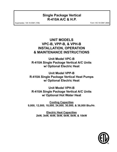
Single Package VerticalR-410A A/C & H.P.Supersedes: 145.19-<strong>IOM</strong>1 (708) Form 145.19-<strong>IOM</strong>1 (908)UNIT MODELSVPC-B, VPP-B, & VPH-BINSTALLATION, OPERATION& MAINTENANCE INSTRUCTIONSUnit Model VPC-BR-410A Single Package Vertical A/C Unitsw/ Optional Electric HeatUnit Model VPP-BR-410A Single Package Vertical Heat Pumpsw/ Optional Electric HeatUnit Model VPH-BR-410A Single Package Vertical A/C Unitsw/ Optional Hot Water HeatCooling Capacities9,000, 12,000, 18,000, 24,000, 30,000, & 36,000 Btu/Hr.Electric Heat Capacities2kW, 3kW, 4kW, 5kW, 6kW, 8kW, & 10kW
FORM 145.19-<strong>IOM</strong>1 (908)IMPORTANT!Read BEFORE PROCEEDING!GENERAL SAFETY GUIDELINESThis equipment is a relatively complicated apparatus.During installation, operation, maintenance or service,individuals may be exposed to certain components orconditions including, but not limited to: refrigerants, oils,materials under pressure, rotating components, andboth high and low voltage. Each of these items has thepotential, if misused or handled improperly, to causebodily injury or death. It is the obligation and responsibilityof operating/service personnel to identify andrecognize these inherent hazards, protect themselves,and proceed safely in completing their tasks. Failure tocomply with any of these requirements could result inserious damage to the equipment and the property inwhich it is situated, as well as severe personal injury ordeath to themselves and people at the site.This document is intended for use by owner-authorizedoperating/service personnel. It is expected that thisindividual possesses independent training that will enablethem to perform their assigned tasks properly andsafely. It is essential that, prior to performing any taskon this equipment, this individual shall have read andunderstood this document and any referenced materials.This individual shall also be familiar with and comply withall applicable governmental standards and regulationspertaining to the task in question.safety symbolsThe following symbols are used in this document to alert the reader to areas of potential hazard:DANGER indicates an imminently hazardoussituation which, if not avoided,will result in death or serious injury.CAUTION identifies a hazard which couldlead to damage to the machine, damageto other equipment and/or environmentalpollution. Usually an instruction willbe given, together with a brief explanation.WARNING indicates a potentially hazardoussituation which, if not avoided,could result in death or serious injury.NOTE is used to highlight additional informationwhich may be helpful to you.All wiring must be in accordance with published specifications and must be performed onlyby qualified service personnel. <strong>Johnson</strong> <strong>Controls</strong> will not be responsible for damages/problemsresulting from improper connections to the controls or application of improper control signals.Failure to follow this will void the manufacturer’s warranty and cause serious damage to propertyor injury to persons.2JOHNSON CONTROLS
FORM 145.19-<strong>IOM</strong>1 (908)Changeability of this documentIn complying with <strong>Johnson</strong> <strong>Controls</strong> policy for continuousproduct improvement, the information containedin this document is subject to change without notice.While <strong>Johnson</strong> <strong>Controls</strong> makes no commitment to updateor provide current information automatically to themanual owner, that information, if applicable, can beobtained by contacting the nearest <strong>Johnson</strong> <strong>Controls</strong>service office.It is the responsibility of operating/service personnel asto the applicability of these documents to the equipmentin question. If there is any question in the mind of operating/servicepersonnel as to the applicability of thesedocuments, then, prior to working on the equipment, theyshould verify with the owner whether the equipment hasbeen modified and if current literature is available.Work on this equipment should only be done by properly trained personnel who are qualified towork on this type of equipment. Failure to comply with this requirement could expose the worker,the equipment and the building and its inhabitants to the risk of injury or property damage.The instructions are written assuming the individual who will perform this work is a fully trainedHVAC & R journeyman or equivalent, certified in refrigerant handling and recovery techniques, andknowledgeable with regard to electrical lock out/tag out procedures. The individual performingthis work should be aware of and comply with all national, state and local safety and environmentalregulations while carrying out this work. Before attempting to work on any equipment,the individual should be thoroughly familiar with the equipment by reading and understandingthe associated service literature applicable to the equipment. If you do not have this literature,you may obtain it by contacting a <strong>Johnson</strong> <strong>Controls</strong> Service Office.Should there be any question concerning any aspect of the tasks outlined in this instruction,please consult a <strong>Johnson</strong> <strong>Controls</strong> Service Office prior to attempting the work. Please be awarethat this information may be time sensitive and that <strong>Johnson</strong> <strong>Controls</strong> reserves the right to revisethis information at any time. Be certain you are working with the latest information.<strong>Johnson</strong> <strong>Controls</strong>3
FORM 145.19-<strong>IOM</strong>1 (908)VPC / VPP, and VPH models provide a complete air-conditioning and optional heating system as an all-in-one package,capable of providing total heating and cooling functions for a single zone or multiple rooms. Specifically designedfor convenient through-the-wall installation in residential high rise and hospitality industry applications. The all-indoordesign eliminates the need for unsightly exterior equipment, thereby maintaining architectural esthetics.All units are shipped completely wired and factory tested. The refrigeration section features enhanced refrigerationcoils, a bi-flow thermostatic expansion valve for refrigerant control, and a high efficiency Scroll or rotary compressor.The VPP units incorporate a reversing valve to allow operation on a heat pump cycle. Air circulating fans arecentrifugal, direct driven. The indoor fan motor allows operation at three different fan speeds.The standard VPC & VPH units may be operated on the cooling cycle to an outdoor ambient of 40ºF. The low ambientcooling package will cycle the compressor to prevent frosting of the evaporator at low outdoor ambient temperatures.The VPP unit locks out compressor operation (refrigerant heating) at outdoor ambient temperatures below 40ºF.TABLE OF CONTENTSNomenclature.......................................................................5Preparing to intall Unit....................................................6Important Safety rules....................................................6Meeting Codes.......................................................................6Unpacking................................................................................6Normal Installation............................................................7Clearances.............................................................................9Wall Opening..........................................................................9Wall Sleeve.............................................................................9Exterior Grill..................................................................... 11Unit to sleeve attachment............................................. 11Condensate Drain Pipiing................................................ 11Hot water piping - VPH...................................................... 11Installing Ductwork........................................................ 11Filter Installation.............................................................13Electrical Connections.................................................13Installing Electrical Wiring.........................................13Sequence of operation...................................................15Unit Section Start-up Checklist..................................16System Balance..................................................................16Maintaining unit in good working order.................17refrigerant Charges...................................................... 17Wiring Diagram - Cooling w/ Electric heat............. 18Wiring Diagram - Heat pump w/ Electric Heat..........19Wiring Diagram - Cooling w/ Hydronic Heat............20Warranty Policy.................................................................234JOHNSON CONTROLS
FORM 145.19-<strong>IOM</strong>1 (908)VPC & VPP UNIT NOMENCLATUREVP C 05 24 12 B - AProduct CategoryVP= Single Packaged Vertical UnitService DigitFactory AssignedUnit TypeC= Air ConditionerP= Air to Air Heat PumpElectric Heat CapacityNominal Heating Capacity in kW00= NO Heat (VPC Units Only)02= 2kW03= 3kW04= 4kW05= 5kW06= 6kW08= 8kW10= 10kWNominal Cooling Capacity36= 36,000 Btuh30= 30,000 Btuh24= 24,000 Btuh18= 18,000 Btuh12= 12,000 Btuh09= 9,000 BtuhVoltage12= 208-230-1-60System TypeB= R-410A RefrigerantVPH UNIT NOMENCLATUREVP H 02 24 12 B - AProduct CategoryVP= Single Packaged Vertical UnitService DigitFactory AssignedUnit TypeH= Air Conditioner w/ Hydronic HeatSystem TypeB= R-410A RefrigerantHydronic Heat CapacityHot Water Coil Type02= 2 Row Coil03= 3 Row CoilNominal Cooling Capacity36= 36,000 Btuh30= 30,000 Btuh24= 24,000 Btuh18= 18,000 Btuh12= 12,000 BtuhVoltage12= 208-230-1-60<strong>Johnson</strong> <strong>Controls</strong>5
FORM 145.19-<strong>IOM</strong>1 (908)IMPORTANT SAFETY NOTE: After installing the unit,show the user how to turn off the electricity to unit.Point out control and switch locations for turning off theelectricity.Make sure user understands the importance of followingall safety precautions.1. PREPARING TO INSTALL UNITA. LiteratureReview this Manual and the Users’ Manual Information.After installing the unit; give this Installer’s InformationManual to the end user. If you need help on anyof the installation instructions or other matters relatingto the unit, contact the office where you boughtthe unit. You may also refer to the unit rating platefor a contact name.b) Allow the shipping base to remain with the unit untilit is ready to be set in its final location.c) Rotate blowers to assure free movement.d) The compressor is mounted on neoprene isolatorswith metal spacing sleeves inside and securedwith nuts, which must be snug against the metalspacer sleeves.e) Check all refrigeration tubing to assure that it doesnot rub against any other parts.5. NORMAL INSTALLATIONThis unit is designed for indoor installation adjacentto an outside wall having an opening for outdoor airflow. The air flow products must:A. Discharge directly to the outside.B. Discharge away from any obstructions which couldcause discharged air recirculation.2. IMPORTANT SAFETY RULES3. MEETING CODESRead and exactly follow these rules.Failure to do so could cause improperunit operation, resulting in damage,injury or death.DO NOT install this unit outdoors.Before installing unit, make sure you know all applicablecodes. National, state and local codesmay take precedence over any instructions in thismanual. Be sure to consult:- Authorities having jurisdiction over units;- Local code authorities for information on electricalwiring.4. UNPACKINGa) Check the unit for indications of damage in shipment.Notify the Transportation company of anydamage and note the damage on the shippingreceipt.Rough handling may dislocate internalcomponents.6JOHNSON CONTROLS
FORM 145.19-<strong>IOM</strong>1 (908)VPC/VPP UNIT DIMENSIONSUnit Model A B C D009 ,012, 018, 024 20 20 9.94 10.94030 & 036 24 25 11 11LD13518Fig. 1 - 3/4 to 3 Ton VPC-B Dimensions & Connection locations<strong>Johnson</strong> <strong>Controls</strong>7
FORM 145.19-<strong>IOM</strong>1 (908)VPH UNIT DIMENSIONSUnit Model A B C D009 ,012, 018, 024 20 20 12.38 14.88030 & 036 24 25 12.38 17.38LD13519Fig. 2 - 3/4 to 3 Ton VPH-B Dimensions & Connection locations8JOHNSON CONTROLS
FORM 145.19-<strong>IOM</strong>1 (908)6. CLEARANCESThe unit is design certified for closet installation withthe minimum clearances to combustible materialsas stated on the data label. No clearance is requiredfrom the top, sides, or back of the unit. A minimumof 1 inch clearance is required from the front to anycombustible materials. A combustible door may beplaced 6 inches from the front of the unit. When thedoor is open there must be 30 inches clearance toany obstruction, to allow sufficient access for serviceand the replacement of parts.8. WALL SLEEVEA factory-made wall sleeve is required to finishthe wall opening. The sleeve should be positionedwith a minimum of ¼” protruding from the finishedoutside wall face. This projection allows installationof the exterior grille without interference from theexterior finishing materials, and provides a rightangle surface to apply a caulking bead around thewall penetration.Use a spirit level or plumb line to make sure that thewall sleeve vertical flanges, which must mate withthe back of the unit, are perfectly vertical. The sleevemust be secured to the building framing with suitablefield-supplied fasteners (i.e. lag screws).Use shims as necessary, between thesleeve and the rough wall opening, tocompensate for any irregularities atthe sleeve fastening locations. DO NOTallow the fasteners to distort the wallsleeve side panels.CLOSETCLEARANCEDIMENSIONS(<strong>Inc</strong>hes)WALL SLEEVETHICKNESS009 - 024UNITS030 & 036UNITS"A" "D" "A" "D"5"- 8" 22 29 -"B" 27 33 -"B"8"- 12" 22 33 -"B" 27 37 -"B"12"- 15" 22 36 -"B" 27 40 -"B"A roll of ¾” wide x ½” thick self adhesive foam gasketis packed in the blower compartment of the unit, tobe used for sealing between the wall sleeve and theunit. Before moving the unit into final position, applyself-adhesive foam gasket to all the mating flangeson the wall sleeve, be sure to apply gasket materialto the divider panel flange between the top and bottomsections of the wall sleeve. Also apply gasketmaterial to the vertical flange of fresh air divider.LD135207. WALL OPENINGA finished opening in an outside wall is required forintake and exhaust of outdoor airflow. The rough-inopening dimensions required are as follows:□ 009 thru 024 Models = 21-3/4” wide by 44” high□ 030 and 036 Models = 26-3/4” wide by 44” highThe bottom edge of wall opening mustbe located at least 6” higher from finishedfloor.Consult local ordinances for framing requirements ofopenings through exterior structural walls.<strong>Johnson</strong> <strong>Controls</strong>9
FORM 145.19-<strong>IOM</strong>1 (908)WALL SLEEVE DIMENSIONSUnit Model B C009 ,012, 018, 024 12.5 21.38030 & 036 16.5 26.38LD13521Fig. 3 - Wall Sleeve Assembly10JOHNSON CONTROLS
FORM 145.19-<strong>IOM</strong>1 (908)9. EXTERIOR GRILLEFinish the sleeve exterior with a factory supplied intakeand discharge grille.10. UNIT TO SLEEVE ATTACHMENTLift the unit and place it inside of the wall sleeve. Thenslide the unit forward until the unit contacts the wallsleeve and makes a seal with the gasket on the wallsleeve. Make sure unit is centered inside of the wallsleeve. The unit is secured to the wall sleeve using twoangles; use of the angles is optional and depends onfield installation conditions. The angles should be placedon the both sides of the unit using prepunched holes toposition them. They must be installed before the unit isput into place.The drain piping on the outlet side of the trap should bepitched ¼ inch per foot down towards an open drain.Unions should be installed between the outlet side ofthe trap to allow for disconnecting the piping and thetrap for cleaning out.12. HOT WATER PIPING – VPH UNITS ONLYThe VPH models are supplied with a 2 or 3-row hot waterheating coil. The water connections to the heating coilproject through the top of the unit cabinet, adjacent tothe supply air opening. The orientation of the water in/ water out through the coil is interchangeable (eitherconnection may be the water in, without affecting heatingoutput).The maximum design entering water temperature forthese units is 200ºF.The sweat connection stubs are 7/8” ID copper. Unionsshould be installed on both the inlet and outlet piping (asclose to the unit as possible), to allow for disconnectingand removal of the entire unit.13. INSTALLING DUCT WORKInstall all duct work to meet currentstandards:• ASHRAE/NFPA 90, Standard for Installation ofWarm Air Heating and Air Systems.• State, provincial, and local codesAfter the unit is positioned screw the angles to the frontflange of the wall sleeve sides using two #10 x ½ inchself-drilling sheet metal screws on each end. The requiredangles and screws are packed inside the blowercompartment of the unit.11. CONDENSATE DRAIN PIPINGThe condensate drain pan is fitted with a ¾” NPT femalepipe fitting which protrudes through the unit wallsleeve bottom casing. The ¾” drain piping should havedrain trap installed to prevent conditioned air from beingblown out of the drain line. The trap should be at least2 inches deep with the outlet a minimum of 1-½ inchbelow the inlet.CLEARANCEFailure to follow these standards could reduce airflow or increase air leakage, resulting in reducedsystem performance or unit damage.For all units, design duct systems within the maximumexternal static pressure limits indicated in Table 1.SUPPLY AIR DUCT WORKDuct attaching hardware must only be used on the supplyair outlet flanges. Optional electrical heater is locatedunder the top panel near these flanges. Do not drill oruse screws in this area.Supply air duct (plenum) connectionmust be at least the same size as theunit supply air opening. Seal supply airduct work to unit casing, walls, ceilingsor floors.<strong>Johnson</strong> <strong>Controls</strong>11
FORM 145.19-<strong>IOM</strong>1 (908)TABLE 1 - CFM and Motor Spped SelectionINDOOR BLOWER CFM - VPC & VPP MODELSModel #vPC/vPP**09vPC/vPP**12vPC/vPP**18vPC/vPP**24vPC/vPP**30vPC/vPP**36MotorExTERNaL STaTIC PRESSuRESpeed 0.05 0.10 0.15 0.20 0.25 0.30 0.35 0.40HIgH 445 435 425 415 400 385 370 355MED 350 340 330 320 310 300 285 270LOW 280 275 270 265 255 245 235 220HIgH 620 618 616 614 612 610 590 570MED 465 460 455 450 445 440 425 415LOW 380 378 376 374 372 370 360 350HIgH 780 770 760 750 740 720 700 675MED 640 640 635 630 625 625 610 595LOW 555 556 557 558 559 560 550 530HIgH 940 915 890 865 840 815 795 765MED 855 845 835 825 815 800 785 765LOW 770 765 760 755 750 740 730 715HIgH 1230 1205 1180 1155 1130 1105 1075 1045MED 1050 1040 1030 1020 1005 985 965 945LOW 925 920 915 910 905 900 890 875HIgH 1320 1300 1275 1250 1220 1190 1160 1125MED 1140 1130 1115 1100 1080 1060 1035 1010LOW - 940 935 930 925 920 905 885INDOOR BLOWER CFM - VPH MODELSModel #vPH02092 ROW H/W COILvPH02122 ROW H/W COILvPH02182 ROW H/W COILvPH03183 ROW H/W COILvPH02242 ROW H/W COILvPH03243 ROW H/W COILvPH02302 ROW H/W COILvPH03303 ROW H/W COILvPH02362 ROW H/W COILvPH03363 ROW H/W COILMotorSpeedExTERNaL STaTIC PRESSuRE0.05 0.10 0.15 0.20 0.25 0.30 0.35 0.40HIgH 435 425 415 400 385 370 355 335MED 340 330 320 310 300 285 270 255LOW 275 270 265 255 245 235 220 205HIgH 610 608 606 604 600 595 575 550MED 455 450 445 440 430 440 410 400LOW 375 373 370 368 366 360 350 340HIgH 740 735 710 690 685 660 635 605MED 620 620 605 600 590 585 570 550LOW 550 551 552 553 554 555 545 525HIgH 705 690 675 665 650 625 600 570MED 610 605 595 585 575 570 550 535LOW 545 546 547 548 549 545 520 505HIgH 820 800 780 755 730 705 690 660MED 815 785 765 735 705 675 645 615LOW 755 750 740 725 695 665 635 600HIgH 780 760 740 720 690 665 650 620MED 765 740 715 690 665 640 615 585LOW 740 725 710 680 660 635 610 580HIgH 1120 1100 1075 1050 1020 990 960 930MED 990 975 955 935 910 885 860 835LOW 920 905 890 875 855 835 815 790HIgH 1070 1045 1020 995 970 945 920 890MED 980 965 945 925 900 875 850 825LOW 910 895 880 865 845 825 805 780HIgH 1185 1165 1140 1115 1090 1065 1035 1005MED 1075 1055 1035 1015 995 970 945 920LOW 940 925 910 895 880 860 840 820HIgH 1145 1125 1100 1075 1050 1025 995 965MED 1050 1030 1010 990 970 945 920 895LOW 930 915 900 885 870 850 830 810NOTE: aLL uNITS SHIPPED FaCTORy CONNECTED aT MEDIuM SPEEDLD1352312JOHNSON CONTROLS
FORM 145.19-<strong>IOM</strong>1 (908)14. AIR FILTERSAll return air entering the unit must be filtered. The returnair is drawn from inside of the unit closet, which servesas a return air plenum. A return air opening on a closetmust be furnished prior to the unit installation, either onthe closet door or one of the side walls.Fresh air for ventilation is drawn in through an adjustableintake damper, which is accessible through thecompressor compartment access door. A washablepolypropylene mesh filter is provided to prevent dust andinsects from entering the indoor circulating air.FILTER INSTALLATIONAir filters are required to keep the airconditioning coil, and blower motorclean. The return air filter can be removedfrom either side (closet spacepermitting), or from the front of the unit.Push the filter all way up into the topfilter flange, slide it into the position andlet it drop into the bottom flange.RECOMMENDED FILTERS SIZEUnit SizeFilter Size3 / 4 Ton 20” x 20” x 1”1 Ton 20” x 20” x 1”1-1/2 Ton 20” x 20” x 1”2 Ton 20” x 20” x 1”2-1/2 Ton 25” x 20” x 1”3 Ton 25” x 20” x 1”The fresh air intake filter can be removed through thecompressor access door. The filter pad is retained behinda small retaining bracket, which is secured to theintake damper assembly with a single screw. Removethe screw and bracket, and extract the filter for inspectionand cleaning.15. ELECTRICAL CONNECTIONSCheck the voltage and phase listed on the unit ratingplate, before installation, to be sure the power supply iscorrect. If the compressor fails as the result of installationor improper voltage, the compressor is not replaceableunder warranty and the manufacturer will not beresponsible for the cost of replacement. The minimumand maximum operating voltages, and fuse sizes, arelisted on the unit rating plate.The power leads must be brought to the entry holeprovided in the unit control box. Line voltage connectionis made to a manufacturer supplied disconnectswitch placed inside of the unit main electrical box. Mainelectrical supply entry hole is provided on the top of allVPC/VPP units.16. INSTALLING ELECTRICAL WIRINGProvide unit with its own separate electricalcircuit, means of circuit protectionand electrical disconnect switch. Followcurrent National Electrical Code ANSI/NFPA 70, CSA C22.1 C.E.C. Part 1, andstate and local codes. Failure to providethese shut-off means could cause electricalshock or fire, resulting in damage,injury or death.Install proper electrical ground to marked groundingterminal in unit junction box. Follow current NationalElectrical Code ANSI/NFPA 70 and local codes, or CSAC22.1 Canadian Electrical Code Part 1.Unit must have proper electrical ground.Failure to provide a proper electricalground could cause electrical shockor fire, resulting in damage, injury ordeath.Select a location for room thermostat that is away fromsupply air registers, on draft-free interior wall, and notnear lights, television, direct sunlight, or other heatsources.<strong>Johnson</strong> <strong>Controls</strong>13
FORM 145.19-<strong>IOM</strong>1 (908)TABLE 2 - ELECtrical DataELECTRICAL DATA - SINGLE PACKAGED VERTICAL UNITS WITH ELECTRIC HEAT OPTION 208-230/1/60MAX FUSE / CCT. BKR. AMPMODEL COMPRESSOR INDOOR FAN OUTDOOR FAN HEATER KWMCA# QTY RLA LRA HP FLA HP FLA 208V 230V 240V 208V 230V 240V 208V 230V 240VvPC/vPP0209 1 @ 3.6 22.2 0.10 0.80 0.10 0.60 1.50 1.84 2.00 10.03 10.98 11.42 15 15 15vPC/vPP0309 1 @ 3.6 22.2 0.10 0.80 0.10 0.60 2.25 2.76 3.00 14.54 15.97 16.63 15 20 20vPC/vPP0409 1 @ 3.6 22.2 0.10 0.80 0.10 0.60 3.00 3.67 4.00 19.06 20.97 21.83 20 25 25vPC/vPP0212 1 @ 4.6 27.9 0.10 0.80 0.13 0.80 1.50 1.84 2.00 10.03 10.98 11.42 15 15 15vPC/vPP0312 1 @ 4.6 27.9 0.10 0.80 0.13 0.80 2.25 2.76 3.00 14.54 15.97 16.63 15 20 20vPC/vPP0412 1 @ 4.6 27.9 0.10 0.80 0.13 0.80 3.00 3.67 4.00 19.06 20.97 21.83 20 25 25vPC/vPP0512 1 @ 4.6 27.9 0.10 0.80 0.13 0.80 3.76 4.59 5.00 23.57 25.96 27.04 25 30 30vPC/vPP0218 1 @ 9.0 48.0 0.13 0.75 0.17 1.10 1.50 1.84 2.00 13.10 13.10 13.10 20 20 20vPC/vPP0318 1 @ 9.0 48.0 0.13 0.75 0.17 1.10 2.25 2.76 3.00 14.48 15.91 16.56 20 20 20vPC/vPP0418 1 @ 9.0 48.0 0.13 0.75 0.17 1.10 3.00 3.67 4.00 18.99 20.90 21.77 20 25 25vPC/vPP0518 1 @ 9.0 48.0 0.13 0.75 0.17 1.10 3.76 4.59 5.00 23.51 25.89 26.98 25 30 30vPC/vPP0618 1 @ 9.0 48.0 0.13 0.75 0.17 1.10 4.51 5.51 6.00 28.02 30.89 32.19 30 35 35vPC/vPP0818 1 @ 9.0 48.0 0.13 0.75 0.17 1.10 6.01 7.35 8.00 37.05 40.87 42.60 40 45 45vPC/vPP1018 1 @ 9.0 48.0 0.13 0.75 0.17 1.10 7.51 9.18 10.00 46.08 50.85 53.02 50 60 60vPC/vPP0324 1 @ 13.5 58.3 0.25 1.50 0.25 1.50 2.25 2.76 3.00 19.88 19.88 19.88 30 30 30vPC/vPP0424 1 @ 13.5 58.3 0.25 1.50 0.25 1.50 3.00 3.67 4.00 19.93 21.84 22.71 30 30 30vPC/vPP0524 1 @ 13.5 58.3 0.25 1.50 0.25 1.50 3.76 4.59 5.00 24.44 26.83 27.92 30 30 30vPC/vPP0624 1 @ 13.5 58.3 0.25 1.50 0.25 1.50 4.51 5.51 6.00 28.96 31.82 33.13 30 35 35vPC/vPP0824 1 @ 13.5 58.3 0.25 1.50 0.25 1.50 6.01 7.35 8.00 37.99 41.81 43.54 40 45 45vPC/vPP1024 1 @ 13.5 58.3 0.25 1.50 0.25 1.50 7.51 9.18 10.00 47.01 51.79 53.96 50 60 60vPC/vPP0530 1 @ 14.1 73.0 0.25 1.50 0.50 3.60 3.76 4.59 5.00 24.44 26.83 27.92 35 35 35vPC/vPP0630 1 @ 14.1 73.0 0.25 1.50 0.50 3.60 4.51 5.51 6.00 28.96 31.82 33.13 35 35 35vPC/vPP0830 1 @ 14.1 73.0 0.25 1.50 0.50 3.60 6.01 7.35 8.00 37.99 41.81 43.54 40 45 45vPC/vPP1030 1 @ 14.1 73.0 0.25 1.50 0.50 3.60 7.51 9.18 10.00 47.01 51.79 53.96 50 60 60vPC/vPP0636 1 @ 16.7 79.0 0.33 2.60 0.50 3.60 4.51 5.51 6.00 30.33 33.20 34.50 40 40 40vPC/vPP0836 1 @ 16.7 79.0 0.33 2.60 0.50 3.60 6.01 7.35 8.00 39.36 43.18 44.92 40 45 45vPC/vPP1036 1 @ 16.7 79.0 0.33 2.60 0.50 3.60 7.51 9.18 10.00 48.39 53.16 55.33 50 60 60ELECTRICAL DATA - SINGLE PACKAGED VERTICAL UNIT WITH 'NO HEAT' OPTION / HYDRONIC HEAT OPTION (208-230/1/60)MODEL COMPRESSORINDOOR FAN OUTDOOR FANMCA MAX FUSE /# QTY RLA LRA HP FLA HP FLA CCT. BKR. AMPvPH**09 / vPC0009 1 @ 3.6 22.2 0.10 0.80 0.10 0.6 5.90 15vPH**12/ vPC0012 1 @ 4.6 27.9 0.10 0.80 0.13 0.8 7.35 15vPH**18 / vPC0018 1 @ 9.0 48.0 0.13 0.75 0.17 1.1 13.10 20vPH**24 / vPC0024 1 @ 13.5 58.3 0.25 1.50 0.25 1.5 19.88 30vPH**30 / vPC0030 1 @ 14.1 73.0 0.25 1.50 0.50 2.8 21.93 35vPH**36 / vPC0036 1 @ 16.7 79.0 0.33 2.60 0.50 2.8 26.28 40LD1352414JOHNSON CONTROLS
FORM 145.19-<strong>IOM</strong>1 (908)18. SEQUENCE OF OPERATION ON HEATINGCYCLE – VPC UNITS ONLY1. Room thermostat calls for heat, connecting R andW terminals.2. Electric Heat sequencer relay (1S) is energized.3. On 2kW through 5kW models the electrical heateris energized between 1-24 seconds after timedelay is energized. Heating fan is energized simultaneouslywith heating element operation.4 . On a unit with two heating elements (6kW, 8kW, or10 kW), the 2nd element will be energized by closureof the 2S sequencer contacts approximately90 seconds after the first stage is energized.5 . When the room thermostat is satisfied, terminalsR and W on the thermostat open, de-energizingthe 1S/2S sequencer relays.6 . The bank of heating elements will be disconnectedin descending order, the indoor fan will continue torun until the elements are deenergized.19. SEQUENCE OF OPERATION ON HEATINGCYCLE – VPH UNITS ONLYFig. 4 - Field Wiring Diagram17. SEQUENCE OF OPERATION ONCOOLING CYCLE – VPC & VPH UNITSLD135251. Room thermostat calls for cooling, connecting Rto Y terminals.2. The compressor and outdoor fan start immediatelyon a call for cooling. Air circulating fan also startsimmediately with cooling operation.3. When the room thermostat is satisfied, terminal Yon the thermostat is de-energized.4. The compressor, outdoor fan and indoor fan stopimmediately when the thermostat is satisfied.5. A compressor restart delay timer is activated atthe end of each cooling cycle. A minimum delaytime of 3 minutes is required to ensure that systempressures have equalized before a compressorrestart.1 . Room thermostat calls for heat, connecting R andW terminals.2 . Hydronic Heat Circulating Pump/valve relay isenergized (field supplied). Heating fan is energizedsimultaneously with hot water flow interlock.(Note: An electric/hot water heat thermostat, whichenergizes the indoor fan during the heating cycle,must be used.)3 . When the room thermostat is satisfied, terminalsR and W on the thermostat open, de-energizingthe hot water pump/valve interlock relay.<strong>Johnson</strong> <strong>Controls</strong>15
FORM 145.19-<strong>IOM</strong>1 (908)20. SEQUENCE OF OPERATION ONCOOLING CYCLE – VPP UNITS ONLY1 . Room thermostat calls for cooling, connecting Rto Y and O terminals (Reversing valve energizedonly in cooling).2 . The compressor and outdoor fan start immediatelyon a call for cooling. Air circulating fan also startsimmediately with cooling operation.3 . When the room thermostat is satisfied, terminalsY and O on the thermostat are de-energized.4 . The compressor, outdoor fan and indoor fan stopimmediately when the thermostat is satisfied. Thereversing valve returns to the default position.5 . A compressor restart delay timer is activated atthe end of each cooling cycle. A minimum delaytime of 3 minutes is required to ensure that systempressures have equalized before a compressorrestart.21. SEQUENCE OF OPERATION ON HEATINGCYCLE – VPP UNITS ONLYA. OUTDOOR AMBIENT ABOVE 40°F1. Room thermostat calls for heat, connecting R andY terminals (O terminal de-energized).2. The compressor and outdoor fan start immediatelyon a call for heating. Air circulating fan also startsimmediately with heating operation.3. When the room thermostat is satisfied, terminal Yon the thermostat is de-energized.4. The compressor, outdoor fan and indoor fan stopimmediately when the thermostat is satisfied.5. A compressor restart delay timer is activated atthe end of each cooling cycle. A minimum delaytime of 3 minutes is required to ensure that systempressures have equalized before a compressorrestart.B. OUTDOOR AMBIENT BELOW 40°F1 . Room thermostat calls for heat, connecting R andY terminals (O terminal de-energized).2 . The normally closed contacts of the Low Ambientrelay (R2) route the thermostat signal throughR3 to energize the electric element switchingsequencers.The heat/cool interlock relay (R3) preventsthe electric heat from being energizedthrough terminal Y of a singlestageheat pump thermostat.3 . On 2kW through 5kW models the electrical heateris energized between 1-24 seconds after timedelay is energized. Indoor fan is interlocked simultaneouslywith heating element operation.4 . On a unit with two heating elements (6kW, 8kW,or 10 kW), the 2nd element will be energizedapproximately 90 seconds after the first stage isenergized.5 . When the room thermostat is satisfied, terminalsR and Y on the thermostat open, de-energizing the1S/2S sequencer relays.6 . The bank of heating elements will be disconnectedin descending order, the indoor fan will continue torun until the elements are deenergized.22. UNIT SECTION START-UP CHECKLISTBefore starting unit for the first time, be sure youcan answer “Yes” to each of these questions:1 . Is the unit level?2 . Have you cleared away all loose construction andinsulation materials?3 . Is unit installed within proper clearances to combustiblematerials?4 . Does electrical wiring follow current NationalElectrical Code ANSI 70 or CSA C22.1 as well aslocal codes?5 . Is unit electrically grounded?6 . Is room thermostat properly installed?7 . Is duct work system correctly sized and sealed?8 . Are air filters in place and correctly sized?23. SYSTEM BALANCEElectric heating elements require a minimumairflow to ensure proper heatingoutput and maximum element operatinglife. Low airflow will also cause poorcooling performance.Blower speed taps are factory set for optimumheating and cooling airflow ranges. Refer to Table1 for factory blower speed settings, and minimumallowable heating airflow.Operating unit below the minimumheating airflow may cause poor heatingperformance and decreased resistantheater life.16JOHNSON CONTROLS
FORM 145.19-<strong>IOM</strong>1 (908)Installed system must be test run to ensure operationwith sufficient heating and cooling airflow.Duct work static pressure should not exceed 0.3inches W.C. in order to ensure proper volume ofair flow.24. MAINTAINING YOUR UNIT IN GOOD WORKINGORDERFollow these procedures before inspectingunit.When operating in Cooling, with a clean outdoorcoil, the air temperature leaving the outdoor fandischarge should be approximately 33°F above theoutdoor air temperature. The saturated condensingtemperature should be approximately 38°F abovethe outdoor air temperature.Outdoor Temp °F Condensing Pressure (psig)70 34075 37080 39085 42090 44595 480• Turn room thermostat to the ‘OFF’ system setting.• Wait at least five minutes for unit to cool if it wasrecently operating.• Turn off unit electrical power; failure to do so couldresult in injury or death.Use only recommended replacementsparts. Failure to do so could cause improperunit operation, resulting in damage,injury or death.Perform periodic preventive maintenance oncebefore heating season begins and once beforecooling season. Inspect, clean and repair asneeded the following items:1) All electrical wiring and connections, includingelectrical ground.2) All supply air and return air ducts for obstructions,air leaks and loose insulation.3) Blower housings, motors and wheels, and air filters.Blower motors do NOT require oiling.4) Inspect indoor and outdoor coils for accumulationsof dirt and debris, and clean as required. If the coilsappear dirty, clean them using mild detergent or acommercial coil cleaning agent.Dirty or clogged indoor coils cause low suctionpressures and lost cooling capacity.If the condensing pressure is higher than shownin the table above, dirt in the condenser must besuspected.To clean the condenser coil, remove the wall grillefrom the outside and remove the accumulated dirtfrom the air intake face of the coil using a brushand/or vacuum cleaner. Always remove all dislodgeddirt from inside the wall sleeve so that itwill not be sucked back into the condenser coil.25. REFRIGERANT CHARGESUNIT MODEL#VP***0912BVP***1212BVP***1812BVP***2412BVP***3012BVP***3612BThe Air Conditioning section of thisequipment is charged with R-410A; ahi-pressure refrigerant. Only qualifiedtechnicians, using appropriately pressure-ratedtest instruments, shouldperform troubleshooting or service onthis equipment.R-410A CHARGE3 lb.- 4 oz.3 lb.- 7 oz.4 lb.- 3 oz.4 lb.- 15 oz.5 lb.- 4 oz.6 lb.- 2 oz.<strong>Johnson</strong> <strong>Controls</strong>17
FORM 145.19-<strong>IOM</strong>1 (908)LD1352618JOHNSON CONTROLS
FORM 145.19-<strong>IOM</strong>1 (908)LD13527<strong>Johnson</strong> <strong>Controls</strong>19
FORM 145.19-<strong>IOM</strong>1 (908)LD1352820JOHNSON CONTROLS
FORM 145.19-<strong>IOM</strong>1 (908)NOTES<strong>Johnson</strong> <strong>Controls</strong>21
FORM 145.19-<strong>IOM</strong>1 (908)NOTES22JOHNSON CONTROLS
FORM 145.19-<strong>IOM</strong>1 (908)LIMITED WARRANTY<strong>Johnson</strong> <strong>Controls</strong> warrants this product to be free from defects in workmanship or material for a period of one year from date of originalinstallation or 18 months from date of shipment, whichever comes first.<strong>Johnson</strong> <strong>Controls</strong> obligation under this Warranty is LIMITED to repairing or replacing at our sole option, at our factory, any part thereofwhich shall be returned to our factory, transportation charges prepaid and which on examination proves to have been thus defectiveunder normal domestic use not exceeding the fuel rating. The defective part should be returned through a qualified servicing dealer.Upon warranty determination, the replacement part will be shipped freight collect and assumes the unexpired portion of this LimitedWarranty.When a defective part can be repaired or replaced, <strong>Johnson</strong> <strong>Controls</strong> shall not be obligated to repair the entire unit or any part thereofother than the defective part.This warranty applies only to the original homeowner, and is subject to the terms and conditions hereof.COMPRESSOR – FIVE YEAR LIMITED WARRANTYIn addition to the One Year Limited Warranty, <strong>Johnson</strong> <strong>Controls</strong> warrants the compressor to be free from defects in workmanship ormaterial for a period of five (5) years from the date of original installation. If a compressor fails during this five year period, a new compressorwill be supplied. The customer will be responsible for freight costs from our factory for delivery of the replacement compressorand also for the return of the defective compressor which may be required under the terms of the Warranty. Labor and any otherexpense involved in replacing the compressor is not covered by this Warranty.LABOR AND COST NOT COVEREDThis Warranty provides only replacement parts or credits, and does not provide for or cover any labor, shipping, handling or other costsfor service travel, servicing, removing, or installing any parts.This Warranty shall be void if:EXCLUSIONS1. The unit is not installed by a licensed or otherwise qualified or contractor and in compliance with the Installation Manual, applicableinstallation and good trade practices.2. The defect or damage is caused by accident, abuse, negligence of any person or company, misuse, riot, flood, fire or Acts ofGod.3. The unit is not operated and regularly serviced and maintained as called for in the Users’ Manual.4. Damages are caused by operating the unit in a commercial or corrosive atmosphere containing any damaging or dangerouschemicals.5. The unit is modified or services in a manner not in accordance with the Installation Manual and Users’ Manual.6. Components, replacement parts, or other accessories not compatible with the unit or not approved by <strong>Johnson</strong> <strong>Controls</strong> havebeen used with or attached to the unit.7. The defect or damage is not caused by <strong>Johnson</strong> <strong>Controls</strong>, or it arises from circumstances beyond the control of <strong>Johnson</strong> <strong>Controls</strong>.8. The unit is installed outside the United States or Canada, or has been removed from the place where it was originally installed.THIS WARRANTY IS IN LIEU OF ALL OTHER WARRANTIES, OBLIGATIONS OR LIABILITIES, EXPRESSED OR IMPLIED BYEMPLOYEES OR REPRESENTATIVES OF JOHNSON CONTROLS. ALL STATUTORY, EXPRESSED OR IMPLIED WARRANTIES,INCLUDING THE IMPLIED WARRANTY OF MERCHANTABILITY AND FITNESS FOR A PARTICULAR PURPOSE ARE HEREBYNEGATED AND EXCLUDED. ANY CLAIMS FOR INCIDENTAL AND CONSEQUENTIAL DAMAGES, OR ANY OTHER DAMAGESOR EXPENSES BEYOND THE TERMS OF THIS LIMITED WARRANTY ARE HEREBY EXPRESSLY NEGATED AND EXCLUDED.<strong>Johnson</strong> <strong>Controls</strong>23
Subject to change without notice. Printed in U.S.A.Copyright © 2008 by Unitary Products Group. All rights reserved.Engineered SystemsProductsGroupP.O. Box 1592York, PA17405Form 145.19-<strong>IOM</strong>1 (908)Supersedes 145.19-<strong>IOM</strong>1 (708)YorkPA17405


