ETST5AW 2" SQUARE THERMOSTAT MOUNTING ... - Enviro-Tec
ETST5AW 2" SQUARE THERMOSTAT MOUNTING ... - Enviro-Tec
ETST5AW 2" SQUARE THERMOSTAT MOUNTING ... - Enviro-Tec
- TAGS
- thermostat
- mounting

Create successful ePaper yourself
Turn your PDF publications into a flip-book with our unique Google optimized e-Paper software.
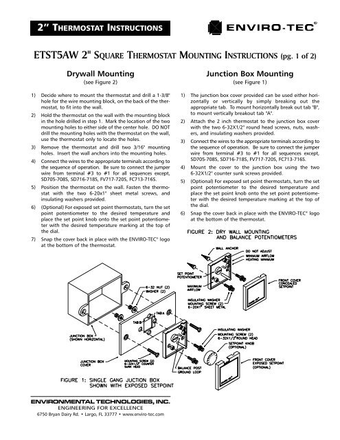
2” <strong>THERMOSTAT</strong> INSTRUCTIONS<strong>ETST5AW</strong> 2" <strong>SQUARE</strong> <strong>THERMOSTAT</strong> <strong>MOUNTING</strong> INSTRUCTIONS (pg. 2 of 2)Balancing Procedures(see Figure 2)These balancing procedures point out only the differencesbetween the large thermostat and the 2" thermostat. Steps from3.0 to 3.3, in the ENVIRO-TEC ® 700 Series O&B manual, shouldbe followed. Steps 1-4 & 10, 11 should be followed for allsequences while steps 5-9 are only used for the particularsequences listed in each step. For constant volume sequences(SD724-SD726S) go directly to step 8.1) Remove the cover by pushing firmly on one side of the topcover and lifting the other side up away from the base. Removethe set point knob (if applicable) from the thermostat. Use theAirflow Calibration Curves in the ENVIRO-TEC ® 700 Series O&Bmanual to determine the Vsp voltages required for the desiredminimum and maximum air flow settings. For SDR boxes use thegraph in Figure 10. For SSD boxes use the graph in Figure 12. Forinstance, if a minimum CFM value of 200 is desired for a 6" SDRbox, the corresponding Vsp voltage is 9.4VDC.2) To read Vsp, connect the red lead (+) from a DC voltmeter tothe post at terminal #5 under the set point potentiometer. Forthermostats with ET numbers before March 1, 1997, connect theblack lead (-) to the left side of D2, above the balance post andto the right of the set point potentiometer. For thermostats withET numbers after March 1, 1997, connect the black lead (-) to theground loop above and to the right of the balance post. Forsequences SD713-SD718S, remove the wire connected toterminal #4.3) Turn the set point potentiometer fully counter clockwise. Verifythe small white potentiometer labeled "AUX" is turned fullyclockwise. Adjust the small white potentiometer labeled "MIN"for the desired minimum voltage for Vsp. If "AUX" is not turnedfully clockwise, this step may not work correctly.4) Turn the set point potentiometer fully clockwise. Adjust thesmall white potentiometer labeled "MAX" for the desiredmaximum voltage for Vsp.Sequences SD701-704S, FV701-704S, FC701-704S FC709-712Sare now balanced.5) Warm up Sequences SD705-708S, SD716-718S, FV717-720S,FC713-716SIf the thermostat has been wired to the controller, the factorysupplied jumper from terminal #1 to #3 should already beremoved and terminal #3 on the thermostat should be connectedto terminal #2 on the controller. This may be a good time toremove the thermostat and verify that the jumper has beenremoved. If the jumper is still on the back of the thermostatremove it and verify the wiring to the sequence. Continue thebalance procedures in the 700 Series O&B manual at step 3.3.4b.6) Dual Minimum Sequences SD713-718Sa) Reconnect the wire on terminal #4 (removed in step #2).b) Connect a DC voltmeter as described in step #2.c) Refer to the Airflow Calibration curves again to determinethe required voltage for the desired heating minimum CFMsetting.d) Turn the temperature set point potentiometer fully counterclockwise. Adjust the small white potentiometer labeled"AUX" until the voltmeter reads the desired voltage.7) Night Setback Sequences FV705-708S, FV721-724S, FC705-708S, FC717-720SThe temperature setting for night set back is located on the controllerat R107, a blue potentiometer in the upper left corner. Thecontroller is factory set at a maximum of 15 degrees below setpoint, R107 turned fully counter clockwise. (i.e. if the thermostatset point is 74 degrees the heat will energize at 59 degrees duringnight set back). Turn R107 fully clockwise for a 5 degreeoffset or turn R107 halfway between the two for a 10 degree offset.8) Constant Volume Sequences SD724-726Sa) Verify that small white potentiometer labeled "AUX" isturned fully clockwise. If it is not turned fully clockwise thisstep may not work correctly.b) Turn the "MAX" potentiometer fully counter clockwise.c) Use the Airflow Calibration Curves in the ENVIRO-TEC ®Operations and Balance Manual to determine the Vspvoltage required for the desired constant airflow setting.For SDR use the graph in Figure 10. For SSD boxes use thegraph in Figure 12. For instance, if a constant CFM valueof 200 is desired for a 6" SDR box, the corresponding Vspvoltage is 9.4VDC.d) To read Vsp, connect a DC volt meter as described instep #2.e) Adjust the small white potentiometer labeled "MIN" for thedesired voltage for Vsp that corresponds to the desiredairflow.9) Dual Duct Sequences DD701SFollow procedures in step 3.3.6 in the 700 Series O&B manualexcept note that the set point potentiometer rotates opposite onthe 2" thermostat. Therefore when the procedure indicates turningthe set point potentiometer clockwise, the set pointpotentiometer on the 2" thermostat must be turned counterclockwise.10) When all the applicable balance procedures from above arecompleted, turn the set point potentiometer to the desired temperature.Place the (optional) set point knob onto the set pointpotentiometer with the desired temperature marking at the topof the dial.11) Snap the cover back in place with the ENVIRO-TEC ® logo atthe bottom of the thermostat.ENVIRONMENTAL TECHNOLOGIES, INC.ENGINEERING FOR EXCELLENCE6750 Bryan Dairy Rd. • Largo, FL 33777 • www.enviro-tec.com