For Models HL, VF and VH Fan Coil Units - Enviro-Tec
For Models HL, VF and VH Fan Coil Units - Enviro-Tec
For Models HL, VF and VH Fan Coil Units - Enviro-Tec
- No tags were found...

Create successful ePaper yourself
Turn your PDF publications into a flip-book with our unique Google optimized e-Paper software.
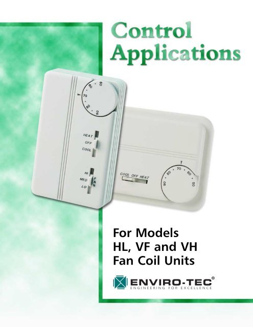
<strong>For</strong> <strong>Models</strong><strong>HL</strong>, <strong>VF</strong> <strong>and</strong> <strong>VH</strong><strong>Fan</strong> <strong>Coil</strong> <strong>Units</strong>
CONTENTS • FCU CONTROL APPS.SELECTION GUIDEInstructionsSingle Point Power. . . . . . . . . . . . . . . . . . . . . . . . . . . . . . . . . . . . . . . . . . . . . . . . . . . . . . . . 4Electric Heat . . . . . . . . . . . . . . . . . . . . . . . . . . . . . . . . . . . . . . . . . . . . . . . . . . . . . . . . . . . . 4Basic Control Options . . . . . . . . . . . . . . . . . . . . . . . . . . . . . . . . . . . . . . . . . . . . . . . . . . . . . 4Low Voltage Options . . . . . . . . . . . . . . . . . . . . . . . . . . . . . . . . . . . . . . . . . . . . . . . . . . . . . . 5Thermostat Options. . . . . . . . . . . . . . . . . . . . . . . . . . . . . . . . . . . . . . . . . . . . . . . . . . . . . . . 5SEQUENCE OF OPERATIONSThermostat CodesT01 . . . . . . . . . . . . . . . . . . . . . . . . . . . . . . . . . . . . . . . . . . . . . . . . . . . . . . . . . . . . . . . . . . . 6T02 . . . . . . . . . . . . . . . . . . . . . . . . . . . . . . . . . . . . . . . . . . . . . . . . . . . . . . . . . . . . . . . . . . . 6T03 . . . . . . . . . . . . . . . . . . . . . . . . . . . . . . . . . . . . . . . . . . . . . . . . . . . . . . . . . . . . . . . . . . . 6T04 . . . . . . . . . . . . . . . . . . . . . . . . . . . . . . . . . . . . . . . . . . . . . . . . . . . . . . . . . . . . . . . . . . . 7T05 . . . . . . . . . . . . . . . . . . . . . . . . . . . . . . . . . . . . . . . . . . . . . . . . . . . . . . . . . . . . . . . . . . . 7T06 . . . . . . . . . . . . . . . . . . . . . . . . . . . . . . . . . . . . . . . . . . . . . . . . . . . . . . . . . . . . . . . . . . . 8T07 . . . . . . . . . . . . . . . . . . . . . . . . . . . . . . . . . . . . . . . . . . . . . . . . . . . . . . . . . . . . . . . . . . . 8T08 . . . . . . . . . . . . . . . . . . . . . . . . . . . . . . . . . . . . . . . . . . . . . . . . . . . . . . . . . . . . . . . . . . . 9T09 . . . . . . . . . . . . . . . . . . . . . . . . . . . . . . . . . . . . . . . . . . . . . . . . . . . . . . . . . . . . . . . . . . . 9T10 . . . . . . . . . . . . . . . . . . . . . . . . . . . . . . . . . . . . . . . . . . . . . . . . . . . . . . . . . . . . . . . . . . . 9T11 . . . . . . . . . . . . . . . . . . . . . . . . . . . . . . . . . . . . . . . . . . . . . . . . . . . . . . . . . . . . . . . . . . 10T12 . . . . . . . . . . . . . . . . . . . . . . . . . . . . . . . . . . . . . . . . . . . . . . . . . . . . . . . . . . . . . . . . . . 10GLOSSARYBasic Control Options<strong>Fan</strong> Speed Controller . . . . . . . . . . . . . . . . . . . . . . . . . . . . . . . . . . . . . . . . . . . . . . . . . . . . . 11Toggle Disconnect Switch . . . . . . . . . . . . . . . . . . . . . . . . . . . . . . . . . . . . . . . . . . . . . . . . . . 11Selectable Speed Motor Terminal Package . . . . . . . . . . . . . . . . . . . . . . . . . . . . . . . . . . . . . . 11Door Interlock Disconnect Switch . . . . . . . . . . . . . . . . . . . . . . . . . . . . . . . . . . . . . . . . . . . . 11Door Interlock Disconnect Switch with Main Fusing. . . . . . . . . . . . . . . . . . . . . . . . . . . . . . . 11Motor Fusing . . . . . . . . . . . . . . . . . . . . . . . . . . . . . . . . . . . . . . . . . . . . . . . . . . . . . . . . . . . 11Control Transformer . . . . . . . . . . . . . . . . . . . . . . . . . . . . . . . . . . . . . . . . . . . . . . . . . . . . . . 11LOW VOLTAGE OPTIONS24 VAC <strong>Fan</strong> Speed Relay Package. . . . . . . . . . . . . . . . . . . . . . . . . . . . . . . . . . . . . . . . . . 1124 VAC Unit Start/Stop Relay . . . . . . . . . . . . . . . . . . . . . . . . . . . . . . . . . . . . . . . . . . . . . 1124 VAC Drain Pan Float Switch Package (<strong>HL</strong> Series Only). . . . . . . . . . . . . . . . . . . . . . . . . 1124 VAC Wall Mounted Thermostat Package . . . . . . . . . . . . . . . . . . . . . . . . . . . . . . . . . . 1124 VAC DX <strong>Fan</strong> Control Relay Package . . . . . . . . . . . . . . . . . . . . . . . . . . . . . . . . . . . . . . 11Wall Mounted 3-Speed <strong>Fan</strong> Switch . . . . . . . . . . . . . . . . . . . . . . . . . . . . . . . . . . . . . . . . . . . 11Unit Mounted 3-Speed <strong>Fan</strong> Switch . . . . . . . . . . . . . . . . . . . . . . . . . . . . . . . . . . . . . . . . . . . 11Motorized Outside Air Damper Option . . . . . . . . . . . . . . . . . . . . . . . . . . . . . . . . . . . . . . . . 11Motorized Outside Air Damper w/Low-Limit Option. . . . . . . . . . . . . . . . . . . . . . . . . . . . . . . 11Aquastat. . . . . . . . . . . . . . . . . . . . . . . . . . . . . . . . . . . . . . . . . . . . . . . . . . . . . . . . . . . . . . . . . 11PREFACEThis document is to be used in conjunction with wiring diagrams found at www.enviro-tec.com <strong>and</strong> withthe <strong>Fan</strong> <strong>Coil</strong> Valve Piping Package catalog (stock ID CAT-FCU-PIPING).©2001 <strong>Enviro</strong>nmental <strong>Tec</strong>hnologies, Inc. • May, 2001 • <strong>Fan</strong> <strong>Coil</strong> Unit Control Applications 3
FCU CONTROL APPS. • SELECTION GUIDEINSTRUCTIONS: Select the option desired from each category by checking the appropriate square.Transfer the selected option to the bid or order documents. Use this document in conjunction with wiringdiagrams found at www.enviro-tec.com.SINGLE POINT POWER VOLTAGESElectric Heat Voltage Motor Voltage Electric Heat Voltage Motor Voltage❏ 120/1/60 120/1/60 ❏ 208/1/60* 120/1/60*❏ 208/1/60 208/1/60 ❏ 230/1/60 230/1/60❏ 277/1/60 277/1/60 ❏ 220/1/50 220/1/50*Requires 3-wire electrical service.ELECTRIC HEATIs Electric Heat Required?❏ Yes❏ NoElectric Heat Notes:• Select kW size from the appropriate price list.• <strong>HL</strong> Series: includes bottom hinged electrical enclosure, single stage contactor, automatic resetprimary limit, backup secondary limit, <strong>and</strong> single point power connection.• <strong>VF</strong> Series: includes finned tubular sheath heater elements, single stage contactor, automatic resetprimary limit, backup secondary limit, <strong>and</strong> single point power connection.• Motor fusing is included on all electric heat units.• Maximum recommended leaving air temperature is 120°F. Check CFM, static pressure <strong>and</strong> entering airtemperature to determine maximum allowable kW.BASIC CONTROL OPTIONS (see Glossary for more information)❏ <strong>Fan</strong> Speed Controller 1 : Series <strong>HL</strong>, <strong>VF</strong> <strong>and</strong> <strong>VH</strong>. Provides incremental fan speed control. Manual adjustment.❏ Toggle Disconnect Switch 2 : Series <strong>HL</strong>, <strong>VF</strong> <strong>and</strong> <strong>VH</strong>. Main power manual disconnect for non electricheat fan coil units.❏ Door Interlock Disconnect Switch: Series <strong>HL</strong> <strong>and</strong> <strong>VH</strong>. Manual disconnect switch for main power.Interlocked with the enclosure door. No main fusing provided. Not applicable for Series <strong>VF</strong> <strong>Fan</strong> <strong>Coil</strong><strong>Units</strong>. Separate non-interlocked disconnect switch without fusing available for Series <strong>VF</strong> <strong>Fan</strong> <strong>Coil</strong> <strong>Units</strong>.❏ Door Interlock Disconnect Switch with Main Fusing: Series <strong>HL</strong> <strong>and</strong> <strong>VH</strong>. Manual disconnect switchfor main power. Interlocked with the enclosure door. Main fusing is provided. Separate non-interlockeddisconnect switch with fusing available for Series <strong>VF</strong> <strong>Fan</strong> <strong>Coil</strong> <strong>Units</strong>.❏ Motor Fusing: Series <strong>HL</strong>, <strong>VF</strong> <strong>and</strong> <strong>VH</strong>. Provides protection for the motor from over current conditions.❏ Wall Mounted 3-Speed <strong>Fan</strong> Switch: Series <strong>HL</strong>, <strong>VF</strong> <strong>and</strong> <strong>VH</strong>. Shipped separate <strong>and</strong> is field installed onthe wall.❏ Unit Mounted 3-Speed <strong>Fan</strong> Switch: Series <strong>HL</strong>, <strong>VF</strong> <strong>and</strong> <strong>VH</strong>. Unit mounted on the fan coil.❏ Motorized Outside Air Damper: Series <strong>VF</strong> <strong>and</strong> <strong>VH</strong>. Adds an O.A. damper to the fan coil unit. Whenfan starts, damper will open.❏ Motorized Outside Air Damper with Low Limit Control Option: Series <strong>VF</strong> <strong>and</strong> <strong>VH</strong>. Includes theO.A. damper <strong>and</strong> a low limit thermostat mounted on the leaving side of the water coil on <strong>VH</strong>, <strong>and</strong> onoutside air stream on <strong>VF</strong> due to space restrictions.4 <strong>Fan</strong> <strong>Coil</strong> Unit Control Applications • May, 2001 • ©2001 <strong>Enviro</strong>nmental <strong>Tec</strong>hnologies, Inc.
LOW VOLTAGE OPTIONSSELECTION GUIDE • FCU CONTROL APPS.❏ 24 VAC <strong>Fan</strong> Speed <strong>and</strong> Temperature Control 4 : Series <strong>HL</strong>, <strong>VF</strong> <strong>and</strong> <strong>VH</strong>. Includes 24 VAC transformer,3 fan speed relays <strong>and</strong> wiring modifications.❏ 24 VAC Unit Start/Stop Relay: Series <strong>HL</strong>, <strong>VF</strong> <strong>and</strong> <strong>VH</strong>. Allows for remote start or stop of the fan coil(such as through a time clock or building automation system).❏ 24 VAC Drain Pan Float Switch 4 : Series <strong>HL</strong> only. Includes 24 VAC transformer, drain pan float switch,terminal wiring package, control relay <strong>and</strong> wiring modifications. Float switch detects water build upin the condensate pan <strong>and</strong> shuts down the fan coil via the 24 VAC control relay.❏ 24 VAC Wall Mounted Thermostat 4 : Series <strong>HL</strong>, <strong>VF</strong> <strong>and</strong> <strong>VH</strong>. Includes 24 VAC transformer, low voltagethermostat, terminal wiring package <strong>and</strong> wiring modifications.❏ 24 VAC DX Control Relay 3 : Series <strong>HL</strong> <strong>and</strong> <strong>VF</strong>. 24 VAC relay to start the fan at a fixed high speed toprovide proper airflow across the DX coil when in refrigeration mode.Notes:1. <strong>Fan</strong> Speed Controller is wired to high motor tap.2. Toggle Switches for use with non electric heat units.3. DX coils are available on <strong>HL</strong> <strong>and</strong> <strong>VF</strong> Series units using thermostat codes T01, T02 <strong>and</strong> T10 only.4. See other applicable notes in the appropriate list price sheets.THERMOSTAT OPTIONSUNIT SURFACE / WALL MOUNTED THERMOSTAT OPTIONSSYSTEMTYPET-STATCODECONTROL TYPECHANGEOVERTYPESYSTEMSWITCHFANSWITCHAQUASTATMOUNTUnitWallT01 Cool Only Heat Only None None None NoT02 Cool Only Heat Only Auto None None YesT03 Cool Only Heat Only None On/Off H - M - L NoT04 Heat/CoolManual Heat/Off/Cool H - M - L Yes2 Pipe T05 Heat/CoolAuto On/Off H - M - L YesT06 Heat/Cool with Aux. Elec. Heat Manual Heat/Off/Cool H - M - L YesT07 Heat/Cool with Aux. Elec. Heat Auto On/Off H - M - L YesT08 Cool with Electric HeatAuto On/Off H - M - L NoT09 Cool with Electric Heat Manual Heat/Off/Cool H - M - L NoT10 Heat/CoolAuto None None No4 Pipe T11 Heat/CoolAuto On/Off H - M - L NoT12 Heat/CoolManual Heat/Off/Cool H - M - L NoAquastat Do not select if included with thermostat code above.Notes:• All thermostat control sequences are continuous fan/valve cycle only.• Line voltage applications are st<strong>and</strong>ard. Low voltage applications are available. Contact your localENVIRO-TEC ® representative for low voltage package information.• Sample control diagrams are available at www.enviro-tec.com.• <strong>VF</strong> <strong>and</strong> <strong>VH</strong> Series fan coils allow for unit or wall mounting of thermostats. <strong>HL</strong> Series have wallmounted thermostats only.• DX coils are available only on <strong>HL</strong> <strong>and</strong> <strong>VF</strong> Series fan coil units with thermostat codes T01, T02 or T10.• Outside air damper options are available on <strong>VF</strong> <strong>and</strong> <strong>VH</strong> Series fan coils only.• We reserve the right to substitute manufacturers of components to improve quality <strong>and</strong> availabilitywithout notice. Options <strong>and</strong>/or voltages may change without notice.©2001 <strong>Enviro</strong>nmental <strong>Tec</strong>hnologies, Inc. • May, 2001 • <strong>Fan</strong> <strong>Coil</strong> Unit Control Applications 5
SEQUENCE OF OPERATIONST01 THERMOSTAT CODE<strong>For</strong> a 2-pipe system. The "Heat or Cool Only" control type utilizes a wall or unit mounted Heating or Coolingthermostat which cycles the water control valve to maintain space temperature. This control optiondoes not include any <strong>Fan</strong> control or Heat/Cool Changeover.SYSTEM FAN: The fan shall run continuously at the speed set by the factory installed jumper. See applicablewiring diagram at www.enviro-tec.com.COOLING ONLY OPERATION: The Cooling thermostat shall cycle the water control valve, via a coolingsignal, to maintain the desired space temperature in reference to the thermostat's setpoint.HEATING ONLY OPERATION: The Heating thermostat shall cycle the water control valve, via a heating signal,to maintain the desired space temperature in reference to the thermostat's setpoint.T02 THERMOSTAT CODE<strong>For</strong> a 2-pipe system. The "Heat/Cool" control type utilizes either a wall or unit mounted Heating/Coolingthermostat which cycles the water control valve to maintain space temperature. This control option includesAuto-Heat/Cool changeover with an Aquastat.AUTO SEASONAL CHANGEOVER: An Aquastat, mounted on the inlet piping to the fan coil, shall sensethe temperature of the water to determine whether the mechanical system is in the Winter or Summermode. If the inlet water temperature is above 83°F, indicating heating, the Aquastat shall divert the coolingsignal <strong>and</strong> connect the heating signal from the thermostat to the control valve to condition the spaceutilizing hot water. When the temperature of the inlet water drops below 65°F, which indicates coolingis available, the Aquastat shall allow the cooling signal to be connected to the control valve to conditionthe space utilizing chilled water.SYSTEM FAN: The fan shall run continuously at the speed set by the factory installed jumper. See applicablewiring diagram at www.enviro-tec.com.COOLING MODE: With the Aquastat in the Summer (Cooling) position, the Heat/Cool thermostat shallcycle the water control valve, via the thermostat's cooling signal, to maintain the desired space temperaturein reference to the thermostat's setpoint.HEATING MODE: With the Aquastat in the Winter (Heating) position, the Heat/Cool thermostat shall cyclethe water control valve, via the thermostat's heating signal, to maintain the desired space temperature inreference to the thermostat's setpoint.T03 THERMOSTAT CODE<strong>For</strong> a 2-pipe system. The "Heat or Cool Only" control type utilizes either a wall or unit mounted Heatingor Cooling thermostat which cycles the water control valve to maintain space temperature. This controloption includes an On/Off System Switch <strong>and</strong> a 3-Speed <strong>Fan</strong> Switch as part of the thermostat.SYSTEM ON/OFF SWITCH: A System ON/OFF Switch, located on the thermostat's cover, shall enable ordisable the fan <strong>and</strong> control valve as directed by the switch's position. The fan shall run continuously withthe system switch in the "On" position <strong>and</strong> shall stop when the system switch is placed in the "Off" position.COOLING ONLY MODE: The Cooling thermostat shall cycle the water control valve, via the cooling signal,to maintain the desired space temperature in reference to the thermostat's setpoint. Heating Only thermostatoption is also available.3-SPEED FAN SWITCH: When the fan coil unit is in the normal operating mode, a <strong>Fan</strong> Speed Switch, locatedon the thermostat cover, shall control the speed of the fan from Low , Medium to High , as directedby the switch's position.6 <strong>Fan</strong> <strong>Coil</strong> Unit Control Applications • May, 2001 • ©2001 <strong>Enviro</strong>nmental <strong>Tec</strong>hnologies, Inc.
SEQUENCE OF OPERATIONST04 THERMOSTAT CODE<strong>For</strong> a 2-pipe system. The "Heat/Cool" control type utilizes either a wall or unit mounted Heating/Coolingthermostat which cycles the water control valve to maintain space temperature. This control option includesManual changeover, Heat/Off/Cool System Switch, 3-Speed <strong>Fan</strong> Switch <strong>and</strong> an Aquastat.MANUAL HEAT/OFF/COOL SYSTEM SWITCH: A System Heat/Off/Cool Switch, located on the thermostat'scover, shall allow the operator to manually select the Heating or Cooling mode of operation or to disablethe fan <strong>and</strong> control valve in the "Off" position. The fan shall run continuously with the system switch inthe Heat or Cool mode (On) <strong>and</strong> shall stop when the system switch is placed in the "Off" position.COOLING MODE: With the Aquastat in the Summer (Cooling) position, the Heat/Cool thermostat, in thecooling position, shall cycle the water control valve, via the cooling signal, to maintain the desired spacetemperature in reference to the thermostat's setpoint.HEATING MODE: With the Aquastat in the Winter (Heating) position, the Heat/Cool thermostat, in theheating position, shall cycle the water control valve, via the heating signal, to maintain the desired spacetemperature in reference to the thermostat's setpoint.SUPERVISORY CHANGEOVER: An Aquastat, mounted on the inlet piping to the fan coil, shall sense thetemperature of the water to determine whether the mechanical system is in the Winter or Summer mode.If the inlet water temperature is above 83°F, indicating heating, the Aquastat shall block the cooling signal<strong>and</strong> connect the heating signal from the thermostat to the control valve to condition the space utilizinghot water. When the temperature of the inlet water drops below 65°F, which indicates cooling is available,the Aquastat shall block the heating signal <strong>and</strong> allow the cooling signal to be connected to the controlvalve to condition the space utilizing chilled water. If the water temperature does not match the manuallyselected Heating or Cooling Mode, the control valve will not open.3-SPEED FAN SWITCH: When the <strong>Fan</strong> <strong>Coil</strong> Unit is in the normal operating mode, a <strong>Fan</strong> Speed Switch,located on the thermostat cover, shall control the speed of the fan from Low , Medium to High , as directedby the switch's position.T05 THERMOSTAT CODE<strong>For</strong> a 2-pipe system. The "Heat/Cool" control type utilizes either a wall or unit mounted Heating/Coolingthermostat which cycles the water control valve to maintain space temperature. This control option includesAuto-Heat/Cool changeover, On/Off System Switch, 3-Speed <strong>Fan</strong> Switch <strong>and</strong> an Aquastat.SYSTEM ON/OFF SWITCH: A System On/Off Switch, located on the thermostat's cover, shall enable or disablethe fan <strong>and</strong> control valve as directed by the switch's position.AUTO HEAT/COOL CHANGEOVER: An Aquastat, mounted on the inlet piping to the fan coil, shall sensethe temperature of the water to determine whether the mechanical system is in the Winter or Summermode. If the inlet water temperature is above 83°F, indicating heating, the Aquastat shall block the coolingsignal <strong>and</strong> connect the heating signal from the thermostat to the control valve to condition the spaceutilizing hot water. When the temperature of the inlet water drops below 65°F, which indicates coolingis available, the Aquastat shall block the heating signal <strong>and</strong> allow the cooling signal to be connected tothe control valve to condition the space utilizing chilled water.COOLING MODE: With the Aquastat in the Summer (Cooling) position, the Heat/Cool thermostat shallcycle the water control water valve in the Cooling Mode to maintain the desired space temperature in referenceto the thermostat's setpoint.HEATING MODE: With the Aquastat in the Winter (Heating) position, the Heat/Cool thermostat shall cyclethe water control water valve in the Heating Mode to maintain the desired space temperature in referenceto the thermostat's setpoint.3-SPEED FAN SWITCH: When the <strong>Fan</strong> <strong>Coil</strong> Unit is in the normal operating mode, a <strong>Fan</strong> Speed Switch,located on the thermostat cover, shall control the speed of the fan from Low , Medium to High , as directedby the switch's position.©2001 <strong>Enviro</strong>nmental <strong>Tec</strong>hnologies, Inc. • May, 2001 • <strong>Fan</strong> <strong>Coil</strong> Unit Control Applications 7
SEQUENCE OF OPERATIONST06 THERMOSTAT CODE<strong>For</strong> a 2-pipe system. The "Heat/Cool" control type utilizes either a wall or unit mounted Heating/Coolingthermostat which cycles the water control valve to maintain space temperature. This control option includesManual changeover, Heat/Off/Cool System Switch, 3 Speed <strong>Fan</strong> Switch <strong>and</strong> an Aquastat.HEAT/OFF/COOL SYSTEM SWITCH: A System Heat/Off/Cool Switch, located on the thermostat's cover, shallallow the operator to manually select Heating, Cooling or to disable the fan <strong>and</strong> control valve in the "Off"position. The fan shall run continuously with the system switch in the Heat or Cool mode (On) <strong>and</strong> shallstop when the system switch is placed in the Off position.COOLING MODE: With the manual Heat/Off/Cool Switch in the "COOL" position, <strong>and</strong> with the Aquastatin the Summer (Cooling) position, a wall or unit mounted Heat/Cool thermostat shall cycle the water controlvalve, via the cooling signal, to maintain the desired space temperature in reference to the thermostat'ssetpoint.HEATING MODE: With the manual Heat/Off/Cool Switch in the "HEAT" position, <strong>and</strong> with the Aquastat inthe Winter (Heating) position, a wall or unit mounted Heat/Cool thermostat shall cycle the water controlvalve, via the heating signal, to maintain the desired space temperature in reference to the thermostat'ssetpoint. If hot water is not available to the fan coil unit, the heating signal shall be switched to the electricheat element(s) through relay CR-1's contacts.SUPERVISORY CHANGEOVER: An Aquastat, mounted on the inlet piping to the fan coil, shall sense thetemperature of the water to determine whether the mechanical system is in the Winter or Summer mode.If the inlet water temperature is above 83°F, indicating heating, the Aquastat shall block the cooling signal<strong>and</strong> connect the heating signal from the thermostat to the control valve to condition the space utilizinghot water. When the temperature of the inlet water drops below 65°F, which indicates cooling is available,the Aquastat shall block the heating signal <strong>and</strong> allow the cooling signal to be connected to the controlvalve to condition the space utilizing chilled water. If the water temperature does not match the manuallyselected Heating or Cooling Mode, the control valve will not open.3-SPEED FAN SWITCH: When the <strong>Fan</strong> <strong>Coil</strong> Unit is in the normal operating mode, a <strong>Fan</strong> Speed Switch,located on the thermostat cover, shall control the speed of the fan from Low, Medium to High, as directedby the switch's position.T07 THERMOSTAT CODE<strong>For</strong> a 2-pipe system. The "Heat/Cool with Auxiliary Electric Heat" control type utilizes either a wall or unitmounted Heating/Cooling thermostat which cycles the water control valve to maintain space temperature.This control option includes Auto-Heat/Cool changeover, On/Off System Switch, 3-Speed <strong>Fan</strong> Switch <strong>and</strong>an Aquastat.SYSTEM ON/OFF SWITCH: A System On/Off Switch, located on the thermostat's cover, shall enable or disablethe fan <strong>and</strong> control valve as directed by the switch's position.AUTO HEAT/COOL CHANGEOVER: An Aquastat, mounted on the inlet piping to the fan coil, shall sensethe temperature of the water to determine whether the mechanical system is in the Winter or Summermode. If the inlet water temperature is above 83°F, indicating heating, the Aquastat shall block the coolingsignal <strong>and</strong> connect the heating signal from the thermostat to the control valve to condition the spaceutilizing hot water. When the temperature of the inlet water drops below 65°F, which indicates coolingis available, the Aquastat shall block the heating signal <strong>and</strong> allow the cooling signal to be connected tothe control valve to condition the space utilizing chilled water.COOLING MODE: With the Aquastat in the Summer (Cooling) position, the Heat/Cool thermostat shallcycle the water control water valve in the Cooling Mode to maintain the desired space temperature in referenceto the thermostat's setpoint.HEATING MODE: With the Aquastat in the Winter (Heating) position, the Heat/Cool thermostat shall cyclethe water control water valve in the Heating Mode to maintain the desired space temperature in referenceto the thermostat's setpoint.8 <strong>Fan</strong> <strong>Coil</strong> Unit Control Applications • May, 2001 • ©2001 <strong>Enviro</strong>nmental <strong>Tec</strong>hnologies, Inc.
SEQUENCE OF OPERATIONS3-SPEED FAN SWITCH: When the <strong>Fan</strong> <strong>Coil</strong> Unit is in the normal operating mode, a <strong>Fan</strong> Speed Switch,located on the thermostat cover, shall control the speed of the fan from Low , Medium to High , as directedby the switch's position.T08 THERMOSTAT CODE<strong>For</strong> a 2-pipe system. The "Cool with Total Electric Heat" control type utilizes either a wall or unit mountedHeating/Cooling thermostat which cycles the chilled water control valve or electric heating elements tomaintain space temperature. This control option includes Auto-Heat/Cool changeover, On/Off System Switch<strong>and</strong> a 3-Speed <strong>Fan</strong> Switch.SYSTEM ON/OFF SWITCH: A System On/Off Switch, located on the thermostat's cover, shall enable or disablethe fan, control valve <strong>and</strong> electric heat as directed by the switch's position.AUTO HEAT/COOL CHANGEOVER: The Auto-changeover function is a feature of the Heat/Cool thermostat.COOLING MODE: The Heat/Cool thermostat, while in the "COOL" mode, shall cycle the chilled water controlwater valve to maintain the desired space temperature in reference to the thermostat's setpoint.HEATING MODE: The Heat/Cool thermostat, while in the "HEAT" mode, shall cycle the electrical heatingelement(s) to maintain the desired space temperature in reference to the thermostat's setpoint.3-SPEED FAN SWITCH: When the <strong>Fan</strong> <strong>Coil</strong> Unit is in the normal operating mode, a <strong>Fan</strong> Speed Switch,located on the thermostat cover, shall control the speed of the fan from Low, Medium to High, as directedby the switch's position.T09 THERMOSTAT CODE<strong>For</strong> a 2-pipe system. The "Cool with Total Electric Heat" control type utilizes either a wall or unit mountedHeating/Cooling thermostat which cycles the chilled water control valve or electric heating elements tomaintain space temperature. This control option includes Manual Changeover, Heat/Off/Cool System Switch<strong>and</strong> a 3-Speed <strong>Fan</strong> Switch.MANUAL HEAT/COOL CHANGEOVER: A "Heat/Off/Cool" switch, mounted on the thermostat, shall allowthe operator to manually select Heating, Cooling or to disable the fan <strong>and</strong> control valves in the "Off" position.COOLING MODE: The Heat/Cool thermostat, while in the "COOL" position, shall cycle the water controlwater valve to maintain the desired space temperature in reference to the thermostat's setpoint.HEATING MODE: The Heat/Cool thermostat, while in the "HEAT" position, shall cycle the electrical heatingelement(s) to maintain the desired space temperature in reference to the thermostat's setpoint.3-SPEED FAN SWITCH: When the <strong>Fan</strong> <strong>Coil</strong> Unit is in the normal operating mode, a <strong>Fan</strong> Speed Switch,located on the thermostat's cover, shall control the speed of the fan from Low, Medium to High, as directedby the switch's position.T10 THERMOSTAT CODE<strong>For</strong> a 4-pipe system. The "Heat/Cool" control type utilizes either a wall or unit mounted Heating/Coolingthermostat which cycles either the heating or cooling control valve to maintain space temperature. Thiscontrol option includes Auto-Heat/Cool changeover Thermostat <strong>and</strong> no other options. <strong>Fan</strong> shall run continuouslyat the high speed as set by the factory installed jumper. The speed may be changed by movingthe jumper to a low speed position or by adjusting the motor speed controller (if applicable).AUTO HEAT/COOL CHANGEOVER: The Auto-changeover function is a feature of the wall or unit mountedHeat/Cool thermostat.©2001 <strong>Enviro</strong>nmental <strong>Tec</strong>hnologies, Inc. • May, 2001 • <strong>Fan</strong> <strong>Coil</strong> Unit Control Applications 9
SEQUENCE OF OPERATIONSCOOLING MODE: The Heat/Cool thermostat, in the cooling mode, shall cycle the chilled water controlwater valve to maintain the desired space temperature in reference to the thermostat's setpoint.HEATING MODE: The Heat/Cool thermostat, in the heating mode, shall cycle the hot water control watervalve to maintain the desired space temperature in reference to the thermostat's setpoint.T11 THERMOSTAT CODE<strong>For</strong> a 4-pipe system. The "Heat/Cool" control type utilizes a wall or unit mounted Heating/Cooling thermostatwhich cycles either the heating or cooling control valve to maintain space temperature. This controloption includes Automatic Heating/Cooling changeover, System Switch <strong>and</strong> <strong>Fan</strong> Speed Switch.SYSTEM ON/OFF SWITCH: A System ON/OFF Switch, located on the thermostat cover, shall enable or disablethe fan <strong>and</strong> control valves as directed by the switch's position.AUTO HEAT/COOL CHANGEOVER: The Auto-changeover function is a feature of the Heat/Cool thermostat.COOLING MODE: The Heat/Cool thermostat, in the cooling mode, shall cycle the chilled water controlwater valve to maintain the desired space temperature in reference to the thermostat's setpoint.HEATING MODE: The Heat/Cool thermostat, in the heating mode, shall cycle the hot water control watervalve to maintain the desired space temperature in reference to the thermostat's setpoint.3 SPEED FAN SWITCH: When the <strong>Fan</strong> <strong>Coil</strong> Unit is in the normal operating mode, a <strong>Fan</strong> Speed Switch,located on the thermostat cover, shall control the speed of the fan from Low, Medium to High, as directedby the switch's position.T12 THERMOSTAT CODE<strong>For</strong> a 4-pipe system. The "Heat/Cool" control type utilizes either a wall or unit mounted Heating/Coolingthermostat which cycles either the heating or cooling control valve to maintain space temperature. The<strong>Fan</strong> shall run continuously during the normal Heat/Cool operation. The fan shall be off when the Heat/Off/CoolSwitch is Off. This control option includes Manual Heating/Cooling changeover <strong>and</strong> a 3-Speed <strong>Fan</strong> Switch.MANUAL HEAT/COOL CHANGEOVER: A "Heat/Off/Cool" switch, mounted on the thermostat, shall allowthe operator to manually select Heating, Cooling or to disable the fan <strong>and</strong> control valves in the "Off" position.COOLING MODE: The Heat/Cool thermostat, while in the "COOL" position, shall cycle the chilled watercontrol water valve to maintain the desired space temperature in reference to the thermostat's setpoint.HEATING MODE: The Heat/Cool thermostat, while in the "HEAT" position, shall cycle the hot water controlwater valve to maintain the desired space temperature in reference to the thermostat's setpoint.3-SPEED FAN SWITCH: When the <strong>Fan</strong> <strong>Coil</strong> Unit is in the normal operating mode, a <strong>Fan</strong> Speed Switch,located on the thermostat's cover, shall control the speed of the fan from Low, Medium to High, as directedby the switch's position.10 <strong>Fan</strong> <strong>Coil</strong> Unit Control Applications • May, 2001 • ©2001 <strong>Enviro</strong>nmental <strong>Tec</strong>hnologies, Inc.
GLOSSARY • FCU CONTROL APPS.<strong>Fan</strong> Speed Controller. Motor speed controller is normally wired to the High speed tap of the motor terminalblock. Allows the motor to be set at speeds incrementally below the high speed setting. Used inairflow balance <strong>and</strong> to efficiently use heating or cooling modes of operation.Toggle Switch. Used to disconnect power on non-electric heat fan coil units only. See Door Interlock DisconnectSwitch option for units with electric heat.Selectable Speed Motor Terminal Package. A terminal block used with a fan that will run continuously.The factory jumper is installed on the High speed motor tap so the fan runs on high speed. Lower speedscan be selected by manually moving the jumper to Medium or Low speed terminal positions.Door Interlock Disconnect Switch. An electrical switch used to disconnect power to the unit before thedoor can be physically opened (for fan coil units with electric heat only). Not applicable to <strong>VF</strong> Series fancoil units. Separate non-interlocked disconnect switch without fusing available for <strong>VF</strong> Series.Door Interlock Disconnect Switch with Main Fusing. Same as Door Interlock Disconnect Switch withmain fusing to protect the fan motor <strong>and</strong> electric strip heat. Door Interlock Disconnect Switch not applicableto <strong>VF</strong> Series fan coil units. Separate non-interlocked disconnect switch with fusing available for <strong>VF</strong>Series.Motor Fusing. Control fuses used to protect the motor <strong>and</strong> control circuits from over current conditions.St<strong>and</strong>ard on fan coils with electric heat.Control Transformer. A 50 VA, 24 VAC transformer, rated at a maximum of 2 AMPs. Consult factory forlarger VA transformers.Wall Mounted 3-Speed <strong>Fan</strong> Switch. <strong>Fan</strong> speed switch suitable for wall mounting.Unit Mounted 3-Speed <strong>Fan</strong> Switch. <strong>Fan</strong> speed switch suitable for unit mounting. Normally used witha wall mounted thermostat. (<strong>Fan</strong> Speed Switches/Thermostat combinations are also available).Motorized Outside Air Damper. Option includes the outside air damper, the actuator (two-position) <strong>and</strong>necessary wiring. Warning: Under outdoor freezing conditions, damage to the water coil may occur if theoutdoor air introduced to the building is not pre-conditioned.Motorized Outside Air Damper With Low Limit Thermostat. This option includes the outside air damper,the actuator (two-position), low limit thermostat <strong>and</strong> necessary wiring. Warning: Under outdoor freezingconditions, damage to the water coil may occur if the outdoor air introduced to the building is notpre-conditioned. This may occur even if the Low-Limit Thermostat is activated <strong>and</strong> the outside damper isclosed.24 VAC <strong>Fan</strong> Speed Relay Package. Package contains (3) 24 VAC relays (one per speed), 24 VAC stepdowncontrol transformer <strong>and</strong> required wiring modifications for proper operation.24 VAC Unit Start/Stop Relay. A relay used to start/stop the fan coil unit from a remote control signalsuch as BAS. Available line voltage or 24 VAC.24 VAC Drain Pan Float Switch Package. Used on <strong>HL</strong> Series fan coil unit only <strong>and</strong> is designed to stopthe fan <strong>and</strong> disable the controls when the drain pan is full of water. Package consists of a Drain Pan FloatSwitch, 24 VAC Step-down Control Transformer, Control Relay, Terminal Wiring Package <strong>and</strong> necessary wiringmodifications for proper operation.24 VAC Wall Mounted Thermostat Package. A 24 VAC thermostat used when engineer specified or ownerrequested because of safety or lower installation cost.24 VAC DX <strong>Fan</strong> Control Relay Package. Used to provide automatic fast fan speed in the cooling mode<strong>and</strong> manual selection of fan speeds in heating modes. Package includes 24 VAC fan control relay, 24 VACstep-down control transformer <strong>and</strong> necessary wiring modifications for proper operation.Aquastat. A strap-on thermostat mounted on the inlet piping to the fan coil <strong>and</strong> senses the temperatureof the water to determine whether the mechanical system is in heating or cooling mode. If the inlet watertemperature is above 83°F, the aquastat will connect the heating signal from the thermostat to heat thespace. When the temperature of the inlet water drops below 65°F, the aquastat shall allow the coolingsignal to be connected to the control valve to cool the space.©2001 <strong>Enviro</strong>nmental <strong>Tec</strong>hnologies, Inc. • May, 2001 • <strong>Fan</strong> <strong>Coil</strong> Unit Control Applications 11
6750 Bryan Dairy Rd. • Largo, FL 33777www.enviro-tec.com727-541-3531©2001 <strong>Enviro</strong>nmental <strong>Tec</strong>hnologies, Inc.Stock ID: CAT-FCU-CONTROLSMay, 2001 • Part No. PX-00-0019Research & Development,Engineering, <strong>and</strong> Manufacturing.• Variable Volume Terminals• <strong>Fan</strong> <strong>Coil</strong> <strong>Units</strong>• Air H<strong>and</strong>ling <strong>Units</strong>• Blower <strong>Coil</strong> <strong>Units</strong>• Grilles, Registers <strong>and</strong> Diffusers, & Fire Dampers• Electronic Controls