VF Series C Vertical Floor Fan Coil Unit - Enviro-Tec
VF Series C Vertical Floor Fan Coil Unit - Enviro-Tec
VF Series C Vertical Floor Fan Coil Unit - Enviro-Tec
- No tags were found...

Create successful ePaper yourself
Turn your PDF publications into a flip-book with our unique Google optimized e-Paper software.
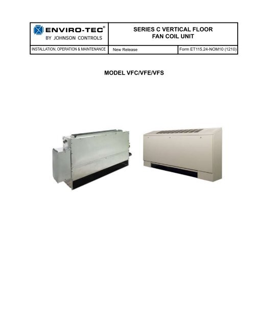
BY JOHNSON CONTROLSInstallation, Operation & MaintenanceSERIES C VERTICAL FLOORFAN COIL UNITNew Release Form ET115.24-NOM10 (1210)Model <strong>VF</strong>C/<strong>VF</strong>E/<strong>VF</strong>S
FORM ET115.24-NOM10 (1210)TABLE OF CONTENTSTABLE OF CONTENTS..................................................................................................................2SAFETY SYMBOLS ......................................................................................................................3SAFETY CONSIDERATIONS.........................................................................................................4SECTION 1 - RECEIPT & INITIAL INSTALLATION......................................................................5<strong>VF</strong> SERIES C FEATURES.......................................................................................................................5PREFACE................................................................................................................................................5UNPACKING & INSPECTION ................................................................................................................6HANDLING & INSTALLATION ...............................................................................................................6COOLING/HEATING MEDIUM CONNECTIONS ...................................................................................7DUCTWORK CONNECTIONS ...............................................................................................................9ELECTRICAL CONNECTIONS ..............................................................................................................9SECTION 2 - START-UP .............................................................................................................10GENERAL .............................................................................................................................................10COOLING/HEATING SYSTEM .............................................................................................................10AIR SYSTEM BALANCING ..................................................................................................................10WATER SYSTEM BALANCING ...........................................................................................................11MOTOR AND FAN DATA.......................................................................................................................11CONTROLS OPERATION ....................................................................................................................12SECTION 3 - NORMAL OPERATION & PERIODIC MAINTENANCE.........................................12GENERAL .............................................................................................................................................12MOTOR/BLOWER ASSEMBLY ...........................................................................................................13COIL ......................................................................................................................................................13ELECTRIC RESISTANCE HEATER ASSEMBLY ................................................................................13FAN DECK.............................................................................................................................................13ELECTRIC HEAT SELECTION CHART...............................................................................................14TOP PANEL REMOVAL (<strong>VF</strong>E, <strong>VF</strong>S).....................................................................................................14ELECTRICAL WIRING & CONTROLS ................................................................................................14VALVES & PIPING................................................................................................................................14FILTERS, THROWAWAY ......................................................................................................................14WALL RECESSING PANEL..................................................................................................................15DRAIN....................................................................................................................................................15REPLACEMENT PARTS ......................................................................................................................15SECTION 4 - INSPECTION, INSTALLATION & START-UP CHECKLIST..................................16SECTION 5 - DIMENSIONAL DRAWINGS..................................................................................17MODEL <strong>VF</strong>C - CONCEALED FAN COIL UNIT.....................................................................................17MODEL <strong>VF</strong>E - EXPOSED FAN COIL UNIT W/ STAMPED SUPPLY GRILLE......................................18MODEL <strong>VF</strong>S - EXPOSED SLOPE TOP FAN COIL UNIT W/ STAMPED SUPPLY AIR GRILLE.........19OUTSIDE AIR DAMPER.......................................................................................................................20OUTSIDE AIR WALL BOX ASSEMBLY................................................................................................21RETURN AIR TOE KICK.......................................................................................................................21MODEL <strong>VF</strong>C - RECESSED WALL PANEL...........................................................................................22FALSE BACK ASSEMBLY & DIMENSIONAL DRAWINGS.................................................................23PARAMETRIC CABINET......................................................................................................................24PIPING PACKAGE SPACE CONSTRAINTS........................................................................................26TROUBLESHOOTING GUIDE FOR FAN COIL RELAY BOARD.........................................................27EXAMPLE WIRING DIAGRAM.............................................................................................................29COIL CONNECTION LOCATIONS.......................................................................................................302ENVIRO-TEC ®
FORM ET115.24-NOM10 (1210)SAFETY SYMBOLSThe following symbols are used in this document to alert the reader to areas of potential hazard:DANGER indicates an imminentlyhazardous situation which, if notavoided, will result in death or seriousinjury.WARNING indicates a potentiallyhazardous situation which, if notavoided, could result in death orserious injury.CAUTION identifies a hazard whichcould lead to damage to the machine,damage to other equipment and/orenvironmental pollution. Usually aninstruction will be given, together witha brief explanation.NOTE is used to highlight additionalinformation which may be helpful toyou.ENVIRO-TEC ® 3
FORM ET115.24-NOM10 (1210)SAFETY CONSIDERATIONSThe equipment covered by this manual is designed forsafe and reliable operation when installed and operatedwithin its design specification limits. To avoid personalinjury or damage to equipment or property whileinstalling or operating this equipment, it is essentialthat qualified, experienced personnel perform thesefunctions using good judgment and safe practices. Seethe following cautionary statements.ELECTRICAL SHOCK HAZARDS.All power must be disconnectedprior to installation and serving thisequipment. More than one source ofpower may be present. Disconnect allpower sources to avoid electrocutionor shock injuries.MOVING PARTS HAZARDS. Motorand Blower must be disconnected priorto opening access panels. Motors canstart automatically, disconnect allpower and control circuits prior toservicing to avoid serious crushing ordismemberment injuries.HOT PARTS HAZARDS. ElectricResistance heating elements must bedisconnected prior to servicing. ElectricHeaters may start automatically,disconnect all power and controlcircuits prior to servicing to avoidburns.All assemblies must be adequatelysecured during lifting and rigging bytemporary supports and restraints untilequipment is permanently fastenedand set in its final location.All unit temporary and permanentsupports must be capable of safelysupporting the equipment’s weight andany additional live or dead loads thatmay be encountered. All supports mustbe designed to meet applicable localcodes and ordinances.All fastening devices must be designedto mechanically lock the assemblyin place without the capability ofloosening or breaking away due tosystem operation and vibration.Secure all dampers when servicingdamper, actuator or linkages. Dampersmay activate automatically, disconnectcontrol circuits or pneumatic controlsystems to avoid injury.Protect adjacent flammable materialswhen brazing, Use flame and heatprotection barriers where needed.Have fire extinguisher available andready for immediate use.Check that the unit assembly andcomponent weights can be safelysupported by rigging and liftingequipment.4ENVIRO-TEC ®
FORM ET115.24-NOM10 (1210)SECTION 1 - RECEIPT & INITIAL INSTALLATION<strong>VF</strong> SERIES C FEATURES(Actual unit will vary by order)510161531142191018871020ITEM QTY TITLE1 2 COVER, BOTTOM, POCKET, <strong>VF</strong>E/S, SERIES C2 2 SUPPORT BRACE, BOTTOM, <strong>VF</strong>E, SERIES C3 2 PANEL, SIDE, EXTERNAL, SERIES C4 1 PANEL, FRONT, <strong>VF</strong>E/S, SERIES C5 1 PANEL, TOP, <strong>VF</strong>E, SERIES C6 1 BACK PANEL, <strong>VF</strong>, SERIES C7 1 DRIP TRAY, <strong>VF</strong>, SERIES C8 1 ASSY, FAN DECK, <strong>VF</strong>, SERIES C9 1 PANEL, BOTTOM, <strong>VF</strong>, SERIES C10 2 BRACKET, COIL, MOUNTING, <strong>VF</strong>, SERIES C11 1 PANEL, BLOWER COVER, <strong>VF</strong>, SERIES C12 1 ASSY, AUXILLIARY DRAIN PAN13 1 RACK, FILTER, <strong>VF</strong>C, SERIES C14 1 FILTER15 1 CONTROL ENCLOSURE16 1 CONTROL ENCLOSURE COVER18 1 ASSY, COIL, <strong>VF</strong>19 1 EH ASSEMBLY, <strong>VF</strong>, SERIES C20 1 ASSY, OUTSIDE AIR, <strong>VF</strong>21 1 PANEL, TOE SPACE, W/SLOTS, <strong>VF</strong>S SERIES C3129111312214PREFACEJohnson Controls fan coils represent a prudentinvestment which can, with proper installation,operation, and regular maintenance, give trouble-freeoperation and long service.Your equipment is initially protected under themanufacturer’s standard warranty; however, thiswarranty is provided under the condition that the stepsoutlined in this manual for initial inspection, properinstallation, regular periodic maintenance, and everydayoperation of the equipment be followed in detail. Thismanual should be fully reviewed in advance of anyactual work being done on the equipment. Shouldany questions arise, please contact your local SalesRepresentative or the factory BEFORE proceeding.The equipment covered by this manual is available witha vast variety of options and accessories. Consult theapproved unit submittal, order acknowledgement, andother manuals for details on the options and accessoriesprovided with the equipment on each project.No attempt should be made to handle,install, or service any unit withoutfollowing safe practices regardingmechanical equipment.<strong>Fan</strong> coil units are designed for indooruse only. Do not install or store fancoils in an outdoor environment.ENVIRO-TEC ® 5
FORM ET115.24-NOM10 (1210)6All power must be disconnected beforeany installation or service should be attempted.More than one power sourcemay be supplied to a unit. Power toremote mounted control devices maynot be supplied through the unit.Never wear bulky or loose fitting clothingwhen working on any mechanicalequipment. Gloves should only beworn when required for proper protectionfrom heat or other possible injury.Safety glasses or goggles shouldalways be worn when drilling, cutting,or working with chemicals such asrefrigerants or lubricants.Never pressurize any equipment beyondspecified operating pressures.Always pressure test with some inertfluid or gas such as clear water or drynitrogen to avoid possible damage orinjury in the event of a leak or componentfailure during testing.Always protect adjacent flammablematerial when welding or soldering.Use suitable heat shield material tocontain sparks or drops of solder.Have fire extinguisher available foruse when welding or brazing.The manufacturer assumes no responsibility for personalinjury or property damage resulting from improperor unsafe practices during the handling, installation,service, or operation of any equipment.UNPACKING & INSPECTIONAll units are carefully inspected at the factory throughoutthe manufacturing process under a strict detailed qualityassurance program, and where possible, all majorcomponents and subassemblies are carefully tested forproper operation and verified to be in full compliancewith the factory manufacturing documents. Customerfurnished components such as control valves, switchesand DDC controls are not factory tested.Each unit is carefully packaged for shipment to avoiddamage during normal transport and handling. Theequipment should always be stored in a dry place in theproper orientation as marked on the carton.All shipments are made F.O.B. factory and it is theresponsibility of the receiving party to inspect theequipment upon arrival. Any obvious damage to thecarton and/or its contents should be recorded on the billof lading and a claim should be filed with the freightcarrier.After determining the condition of the carton exterior,carefully remove each unit from the carton and inspectfor hidden damage. At this time check to make sure that“furnished only” items such as switches, thermostats,etc. are accounted for. Any hidden damage should berecorded and immediately reported to the carrier and aclaim filed as before. In the event a claim for shippingdamage is filed, the unit, shipping carton, and all packingmust be retained for physical inspection by the freightcarrier.All equipment should be stored in the factory-shippingcarton with internal packing in place until installation.At the time of receipt, the equipment type andarrangement should be verified against the orderdocuments. Should any discrepancy be found, the localSales Representative should be notified immediatelyso that the proper action may be instituted. Shouldany question arise concerning warranty repairs, thefactory must be notified BEFORE any correctiveaction is taken. Where local repairs or alterations canbe accomplished, the factory must be fully informed asto the extent and expected cost of those repairs beforework is begun. Where factory operations are required,the factory must be contacted for authorization to returnequipment and a Return Authorization Number will beissued. Unauthorized return shipments of equipmentand shipments not marked with an authorization numberwill be refused. In addition, the manufacturer will notaccept any claims for unauthorized expenses.HANDLING & INSTALLATIONWhile all equipment is designed for durability andfabricated for sturdy construction and may present arugged appearance, great care must be taken to assurethat no force or pressure be applied to the coil, pipingor drain stub-outs during handling. Also, dependingon the options and accessories, some units couldcontain delicate components that may be damaged byimproper handling. Wherever possible, all units shouldbe maintained in an upright position and handled bythe chassis as close as possible to the mounting pointlocations.ENVIRO-TEC ®
FORM ET115.24-NOM10 (1210)In the case of a full cabinet unit, the unit must obviouslybe handled by the exterior casing. This is acceptableproviding the unit is again maintained in an uprightposition and no impact forces are applied that maydamage internal components or painted surfaces. Theequipment covered in this manual IS NOT suitablefor outdoor installations. The equipment should neverbe stored or installed where it may be subjected to ahostile environment such as rain, snow, or extremetemperatures.During and after installation, special care must be takento prevent foreign material such as paint, plaster, anddrywall dust from being deposited in the drain pan oron the motor or blower wheels. Failure to do so mayhave serious adverse effects on unit operation and inthe case of the motor and blower assembly, may resultin immediate or premature failure. All manufacturers’warranties are void if foreign material is deposited onthe motor or blower wheels of any unit. Some units and/or job conditions may require some form of temporarycovering during construction.While the manufacturer does not become involvedin the design and selection of support methods andcomponents, it should be noted that unacceptablesystem operating characteristics and/or performancemay result from improper or inadequate unit structuralsupport. In addition, adequate clearance must beprovided for service and removal of the equipment andits accessory components. Anchoring the equipment inplace is accomplished by using the mounting pointsprovided and positioning the unit to maintain the uniton a LEVEL plane. The drain pan is internally slopedtoward the outlet connection. Care must be taken toinsure that the unit drain pan does not slope away fromthe outlet connection.The unit's drain pan is factory slopedtoward the drain connection when theunit is installed level and plumb.<strong>Vertical</strong> units are designed to be floor mounted orotherwise supported from below and bolted to the wallstructure through the mounting holes provide in thechassis. <strong>Vertical</strong> concealed units are designed to befloor mounted or otherwise supported from below andmay be anchored directly through the cabinet back.<strong>Unit</strong>s with leveling legs must be anchored through thecabinet back.If equipped with optional leveling legs, the legs canbe adjusted with a wrench before anchoring the unitin place.The type of mounting device is a matter of choice,however the mounting point should always be thatprovided in the chassis, or cabinet. Refer to the unitproduct drawing for mounting hole location and sizes.See pages 17, 18 or 19.If equipped with optional falseback spacers or subbases,these accessories must first be assembled and mountedto the unit before anchoring.After mounting the unit, it is then ready for the variousservice connections such as water, drain and electrical.At this time it should be verified that the proper typesof service are actually provided to the unit.On those units requiring chilled water and/or hot water,the proper line size and water temperature should beavailable to the unit. In the case of refrigerant cooling,the proper line size and refrigerant type should beavailable at the unit. The auxiliary drain pan is shippedloose for field installation. See the Auxiliary Drain PanInstallation Details for instructions (next page). Onunits with steam heating coils, the proper line sizingand routing should be verified and the maximum steampressure applied to the unit should never exceed 15psig. The drain piping and steam trap should be sizedand routed to allow for proper condensate flow. Theelectrical service to the unit should be compared tothe unit nameplate to verify compatibility. The routingand sizing of all piping, and the type and sizing of allwiring and other electrical components such as circuitbreakers, disconnect switches, etc. should be determinedby the individual job requirements and should not bebased on the size and/or type of connection providedon the equipment. All installations should be made incompliance with all governing codes and ordinances.Compliance with all codes is the responsibility of theinstalling contractor.COOLING/HEATING MEDIUM CONNECTIONSToxic residues and loose particlesresulting from manufacturing andfield piping techniques such as jointcompounds, soldering flux, and metalshavings may be present in the unitand the piping system. Special considerationmust be given to systemcleanliness when connecting to solar,domestic or potable water systems.ENVIRO-TEC ® 7
FORM ET115.24-NOM10 (1210)Submittals and Product Catalogs detailing unit operation,controls, and connections should be thoroughlyreviewed BEFORE beginning the connection of thevarious cooling and/or heating mediums to the unit.All accessory valve packages should be installed asrequired, and all service valves should be checked forproper operation.If coil and valve package connections are to be madewith “sweat” or solder joint, care should be taken toassure that no components in the valve package aresubjected to a high temperature which may damage sealsor other materials. Many two-position electric controlvalves, depending on valve operation, are provided witha manual-opening lever. This lever should be placedin the “open” position during all soldering or brazingoperations. Valve bodies should be wrapped with a wetrag to help dissipate heat encountered during brazing.If the valve package connection at the coil is made witha union, the coil side of the union must be preventedfrom twisting (“backed up”) during tightening to preventdamage to the coil tubing. Over-tightening must beavoided to prevent distorting the union seal surface anddestroying the union.In the case of field installed valves and piping, thechilled water valve cluster (or expansion valve on DXunits) should be installed in such a way that any drippingor sweating is contained in the auxiliary drain pan orother device.In the case of factory mounted piping packages, itis important to verify that all unions are tight, sinceshipping and handling may cause loosening.After the connections are completed, the system shouldthen be tested for leaks. Since some components are notdesigned to hold pressure with a gas, hydronic systemsshould be tested with water.All water coils must be protected fromfreezing after initial filling with water.Even if the system is drained, unit coilsmay still hold enough water to causedamage when exposed to temperaturesbelow freezing.Refrigerant systems should be tested with dry nitrogenrather than air to prevent the introduction of moistureinto the system. In the event that leaking or defectiveNOTES:1. Bend lower support tabs down 90°.2. Bend upper support tabs up 90°.3. Position drain pan in place and then bend uppersupport tabs down until pan is secure.4. Bend float switch mount out 90° if needed.5. Standard pan shown; typical for extended pan.NOTE:Installing contractor must ensure that the connecteddrain piping maintains the proper pan orientation.8ENVIRO-TEC ®
FORM ET115.24-NOM10 (1210)components are discovered, the Sales Representativemust be notified BEFORE any repairs are attempted.All leaks should be repaired before proceeding withthe installation.ELECTRICAL CONNECTIONSAfter system integrity has been established the pipingshould be insulated in accordance with the projectspecifications. ALL chilled water piping and valves orrefrigerant suction piping not located over drain pansmust be insulated to prevent damage from sweating.This includes factory and field piping inside the unitcabinet.The drain should always be connected and piped to anacceptable disposal point. For proper moisture carryoff,the drain piping should be sloped away from theunit at least 1/8" per foot. A drain trap may be requiredby local codes and it is strongly recommended for odorcontainment.DUCTWORK CONNECTIONSAll ductwork and/or supply and return grilles shouldbe installed in accordance with the project plans andspecifications. If not included on the unit or furnishedfrom the factory, supply and return grilles should beprovided as recommended in the product catalog.All units must be installed in non-combustible areas.Some models are designed to be connected to duct-workwith a MINIMUM amount of external static pressure.These units may be damaged by operation without theproper ductwork connected. Consult the approvedsubmittals and the product catalog for unit externalstatic pressure limitations.<strong>Unit</strong>s provided with outside air for ventilation shouldhave some form of low temperature protection toprevent coil freeze-up.It should be noted that none of these methods wouldadequately protect a coil in the event of power failure.The safest method of freeze protection is to use glycolin the proper percent solution for the coldest expectedair temperature.The manufacturer assumes no responsibility forundesirable system operation due to improperdesign, equipment or component selection, and/orinstallation of ductwork, grilles, and other field suppliedcomponents.electrical quick connect<strong>VF</strong> units allow for a single technician to service the fan/motor by keeping the fan deck to less than 44". Motorsare supplied with quick connectors to allow electrical servicewithout the need for tools.ELECTRICAL CONNECTIONSThe unit nameplate lists the unit electrical characteristicssuch as the required supply voltage, fan and heateramperage and required circuit ampacities. The unitwiringdiagram shows all unit and field wiring. Sinceeach project is different and each unit on a project maybe different, the installer must be familiar with thewiring diagram and nameplate on the unit BEFOREbeginning any wiring. All components furnished forfield installation, by either the factory or the controlscontractor should be located and checked for properfunction and compatibility. All internal componentsshould be checked for shipping damage and all electricalconnections should be tightened to minimize problemsduring start-up.Any devices such as fan switches or thermostatsthat have been furnished from the factory for fieldinstallation must be wired in strict accordance with theapplicable wiring diagrams. Failure to do so could resultin personal injury or damage to components and willvoid all manufacturers’ warranties.The fan motor(s) should never be controlled by anywiring or device other than the factory furnishedswitch, thermostat/switch combination, without factoryauthorization.ENVIRO-TEC ® 9
FORM ET115.24-NOM10 (1210)All field wiring should be done in accordance withgoverning codes and ordinances. Any modification ofthe unit wiring without factory authorization will resultin voiding of all factory warranties and will nullify anyagency listings.The manufacturer assumes no responsibility for anydamages and/or injuries resulting from improperly fieldinstalled or wired components.<strong>Fan</strong> speed can be varied with optional SCR. SCR isshipped wired to high speed tap only. Wiring to mediumor low taps could cause excessive vibration, noise andoverheating which can lead to motor failure.10SECTION 2 - START-UPGENERALBefore beginning any start-up operation, the startuppersonnel should familiarize themselves with theunit, options and accessories, and control sequence tounderstand the proper system operation. All personnelshould have a good working knowledge of generalstart-up procedures and have the appropriate start-upand balancing guides available for consultation.The initial step in any startup operation should be a finalvisual inspection. All equipment, plenums, duct-work,and piping should be inspected to verify that all systemsare complete and properly installed and mounted, andthat no debris or foreign articles such as paper or drinkcans are left in the units or other areas. Each unit shouldbe checked for loose wires, free blower wheel operation,and loose or missing access panels or doors. Except asrequired during start-up and balancing operations, nofan coil units should be operated without all the properductwork attached, supply and return grilles in place,and all access doors and panels in place and secure.A clean filter of the proper size and type must also beinstalled. Failure to do so could result in damage to theequipment or building and furnishings, and/or void allmanufacturers’ warranties.COOLING/HEATING SYSTEMPrior to the water system start-up and balancing, thechilled/hot water systems should be flushed to cleanout dirt and debris, which may have collected in thepiping during construction. During this procedure,all unit service valves must be in the closed position.This prevents foreign matter from entering the unit andclogging the valves and metering devices. Strainersshould be installed in the piping mains to preventthis material from entering the units during normaloperation.During system filling, air venting fromthe unit is accomplished by the use of thestandard, manual or optional automatic airvent fitting installed on the coil. In the caseof the manual air vent fitting, the screwshould be turned counterclockwise no morethan 1-1/2 turns to operate the air vent. Automatic airvents may be unscrewed one turn counterclockwiseto speed initial venting but should be screwed in forautomatic venting after start-up operations.The air vent provided on the unit is notintended to replace the main system airvents and may not release air trappedin other parts of the system. Inspect theentire system for potential air traps andvent those areas as required, independently.In addition, some systems mayrequire repeated venting over a periodof time to properly eliminate air fromthe system.<strong>Fan</strong> coil units are not intended for useas temporary heat/cool or ventilationduring building construction. Theunits are not designed or equippedto operate in a dusty environment.<strong>Fan</strong> wheels can become coated withconstruction dust, resulting in anunbalanced wheel. This can in turncontribute to reduced motor life. Inletfilters cannot provide adequate protectionas they will quickly becomeclogged. Failure to operate the unitin the condition outlined above couldresult in damage to the equipment orbuilding and furnishings, and/or voidall manufacturer’s warranties.Do not operate unit without panelsfully installed.Do not allow supply or return airgrilles to be blocked.Make sure units are properly wiredprior to unit startup.AIR SYSTEM BALANCINGAll ductwork must be complete and connected, and allgrilles, filters, access doors and panels must be properlyinstalled to establish actual system operating conditionsBEFORE beginning air balancing operations.Each individual unit and attached ductwork is a uniquesystem with its own operating characteristics. For thisENVIRO-TEC ®
FORM ET115.24-NOM10 (1210)reason, balance specialists who are familiar with allprocedures required to properly establish air distributionand fan system operating conditions normally do airbalancing. Unqualified personnel should not attemptthese procedures. Exposed units with no ductwork donot require air balancing other than selecting the desiredfan speed.After the proper system operation is established,the actual unit air delivery and the actual fan motoramperage draw for each unit should be recorded ina convenient place for future reference such as theinspection, installation, & start-up check sheet, a copyof which is provided at the back of this manual. Contactthe Sales Representative or the factory for additionalcopies of this sheet.WATER SYSTEM BALANCINGA complete knowledge of the hydronic system, itscomponents, and controls is essential to proper watersystem balancing and this procedure should not beattempted by unqualified personnel. The system mustbe complete and all components must be in operatingcondition BEFORE beginning water system balancingoperations.Each hydronic system has different operatingcharacteristics depending on the devices and controlsin the system. The actual balancing technique may varyfrom one system to another.After the proper system operation is established, theappropriate system operating conditions such as variouswater temperatures and flow rates should be recordedin a convenient place for future reference such as theinspection, installation, & start-up check sheet, a copyof which is provided on the back of this manual. Contactthe Sales Representative or the factory for additionalcopies of this sheet.MOTOR AND FAN DATAUNITMOTOR H.P.115 VOLTS208-230 VOLTS 277 VOLTSFAN SPEED# OF FANSSIZE(QTY.)FLA WATTS FLA WATTS FLA WATTSHigh 45 53 5702 Medium (1) 1/50 1 0.40 35 0.27 41 0.21 44Low 28 36 40High 60 67 7303 Medium (1) 1/20 1 0.60 48 0.40 54 0.31 60Low 43 49 54High 70 71 7604 Meduim (1) 1/20 2 0.75 61 0.39 60 0.35 65Low 58 52 58High 80 81 8706 Medium (1) 1/20 2 0.75 74 0.39 71 0.35 77Low 61 59 64High 114 109 11408 Medium (1) 1/10 2 1.10 81 0.51 77 0.46 80Low 71 66 70High 132 140 14410 Medium (2) 1/20 4 1.50 114 0.78 116 0.70 120Low 107 101 106High 142 147 15412 Medium (2) 1/20 4 1.50 126 0.78 125 0.70 131Low 114 107 114NOTES:1. <strong>VF</strong>E, 3-row coil, no EH, no toe kick, standard throw away panel filter.2. Data was taken without ductwork.3. <strong>Unit</strong> size 04, 06, 08, 10 and 12 data generated at 115v, 230v and 277v.4. <strong>Unit</strong> size 02 & 03 data generated with 115v, 240v to 120v transformer(230v line voltage) and 277v to 120v transformer(277v line voltage).5. For FLA use unit voltage, and size at high speed.ENVIRO-TEC ® 11
FORM ET115.24-NOM10 (1210)Before and during water system balancing, conditionsmay exist which can result in noticeable waternoise or undesired valve operation due to incorrectsystem pressures. After the entire system is balanced,these conditions will not exist on properly designedsystems.CONTROLS OPERATIONBefore proper control operation can be verified all othersystems must be in proper operation. The correct waterand air temperatures must be present for the controlfunction being tested. Some controls and features aredesigned to not operate under certain conditions.A wide range of controls and electrical options andaccessories may be used with the equipment coveredin this manual. Consult the approved unit submittals,order acknowledgement, and other manuals for detailedinformation regarding each individual unit and itscontrols. Since controls and features may vary fromone unit to another, care should be taken to identifythe controls to be used on each unit and their propercontrol sequence. Information provided by componentmanufacturers regarding installation, operation, andmaintenance of their individual controls is availableupon request.SECTION 3 - NORMAL OPERATION& PERIODIC MAINTENANCEGENERALEach unit on a job will have its own unique operatingenvironment and conditions that may dictate amaintenance schedule for that unit that is differentfrom other equipment on the job. A formal schedule ofregular maintenance and an individual unit log shouldbe established and maintained. This will help to achievethe maximum performance and service life of each uniton the job.Information regarding safety precautionscontained in the preface at thebeginning of this manual should befollowed during any service and maintenanceoperations.For more detailed information concerning serviceoperations, consult your Sales Representative or theFactory.510161531142191018871020ITEM QTY TITLE1 2 COVER, BOTTOM, POCKET, <strong>VF</strong>E/S, SERIES C2 2 SUPPORT BRACE, BOTTOM, <strong>VF</strong>E, SERIES C3 2 PANEL, SIDE, EXTERNAL, SERIES C4 1 PANEL, FRONT, <strong>VF</strong>E/S, SERIES C5 1 PANEL, TOP, <strong>VF</strong>E, SERIES C6 1 BACK PANEL, <strong>VF</strong>, SERIES C7 1 DRIP TRAY, <strong>VF</strong>, SERIES C8 1 ASSY, FAN DECK, <strong>VF</strong>, SERIES C9 1 PANEL, BOTTOM, <strong>VF</strong>, SERIES C10 2 BRACKET, COIL, MOUNTING, <strong>VF</strong>, SERIES C11 1 PANEL, BLOWER COVER, <strong>VF</strong>, SERIES C12 1 ASSY, AUXILLIARY DRAIN PAN13 1 RACK, FILTER, <strong>VF</strong>C, SERIES C14 1 FILTER15 1 CONTROL ENCLOSURE16 1 CONTROL ENCLOSURE COVER18 1 ASSY, COIL, <strong>VF</strong>19 1 EH ASSEMBLY, <strong>VF</strong>, SERIES C20 1 ASSY, OUTSIDE AIR, <strong>VF</strong>21 1 PANEL, TOE SPACE, W/SLOTS, <strong>VF</strong>S SERIES C312911131221412ENVIRO-TEC ®
FORM ET115.24-NOM10 (1210)MOTOR/BLOWER ASSEMBLYTo access electrical limits, remove protective cover.Motor/blower assembly can be removed by pulling twoscrews from the frame. <strong>Fan</strong> deck designed to not exceed44".The type of fan operation is determined by the controlcomponents and their method of wiring, and may varyfrom unit to unit. Refer to the wiring diagram for eachunit for that unit’s individual operating characteristics.Motors are permanently lubricated, PSC type and do notrequire field lubrication.Should the assembly require more extensive service,the motor/blower assembly may be removed from theunit to facilitate such operations as motor or blowerwheel/housing replacement, etc. Dirt and dust shouldnot be allowed to accumulate on the blower wheel orhousing. This can result in an unbalanced blower wheelcondition that can damage a blower wheel or motor.The wheel and housing may be cleaned periodicallyusing a vacuum cleaner and a brush taking care not todislodge the factory balancing weights on the blowerwheel blades.COILRemove screws to replace coil.<strong>Coil</strong>s may be cleaned in place by removing the motor/blower assemblies and brushing the entering air facebetween fins with a stiff brush. Cleaning with a vacuumcleaner should follow brushing. If a compressed airsource is available, the coil may also be cleaned byblowing air through the coil fins from the leavingair face. Vacuuming should again follow this. <strong>Unit</strong>sprovided with the proper type of air filters, replacedregularly, will require coil cleaning.ELECTRIC RESISTANCE HEATER ASSEMBLYElectric resistance heaters typically require no normalperiodic maintenance when unit air filters are changedproperly. Other conditions and equipment may affect theoperation and service life in the system. The two mostimportant operating conditions for an electric heater areproper airflow and proper supply voltage. High supplyvoltage and/or poorly distributed or insufficient airflowover the element will result in element overheating. Thiscondition may result in the heater cycling on the highlimit thermal cutoutSheathed type heaters provided have an automaticreset switch with a back-up high limit thermal switch.Automatic reset switches are as the name implies; theyreset automatically after the heater has cooled down.High limit thermal switches must be replaced once thecircuit has been broken. The high limit thermal cutoutdevice is a safety device only and is not intended forcontinuous operation. With proper unit application andduring normal operation, the high limit thermal cutoutwill not operate. This device only operates when someproblem exists and ANY condition that causes high limitcutout MUST be corrected immediately. High supplyvoltage also causes excessive amperage draw and mayresult in tripping of the circuit breaker or blowing ofthe fuses on the incoming power supply.FAN DECKThe fan/drain pan assembly is easily removable forservice access to motors and blowers at, or away from,the unit.ENVIRO-TEC ® 13
FORM ET115.24-NOM10 (1210)UNITSIZE02030406081012<strong>VF</strong> Electric Heat Selection Chart (AMPs)NOTES:AMPS1. Shaded areas of the electric heat selectionchart indicate kW and voltage options notavailable.MBH 3.4 5.1 6.8 10.2 13.7 17.1 20.5KW 1.0 1.5 2.0 3.0 4.0 5.0 6.0VOLTS115 8.3208 4.8240 4.2277 3.6115 8.3 12.5208 4.8 7.2240 4.2 6.3277 3.6 5.4115 8.3 12.5 16.7208 4.8 7.2 9.6240 4.2 6.3 8.3277 3.6 5.4 7.2115 8.3 12.5 16.7 25.0208 4.8 7.2 9.6 14.4240 4.2 6.3 8.3 12.5277 3.6 5.4 7.2 10.8115 8.3 12.5 16.7 25.0208 4.8 7.2 9.6 14.4 19.2240 4.2 6.3 8.3 12.5 16.7277 3.6 5.4 7.2 10.8 14.4115 8.3 12.5 16.7 25.0208 4.8 7.2 9.6 14.4 19.2 24.0240 4.2 6.3 8.3 12.5 16.7 20.8277 3.6 5.4 7.2 10.8 14.4 18.1115 8.3 12.5 16.7 25.0208 4.8 7.2 9.6 14.4 19.2 24.0 28.9240 4.2 6.3 8.3 12.5 16.7 20.8 25.0277 3.6 5.4 7.2 10.8 14.4 18.1 21.72. Available voltages are single phase,60 hertz.3. Size heater for Leaving Air Temperature(LAT) less than 104°F.4. Silent, solid state heater relay is availablefor heater currents less than 18 amps.5. Ask your representative about continuouslymodulating electric heat using SSR and specialcontrol options.TOP PANEL REMOVAL (<strong>VF</strong>S, <strong>VF</strong>E)Depending on options and unit size, the top panelmay need to be removed to service or replace fan coilcomponents. Top panel removal does not require theunit to be pulled away from wall, or for piping/electricalconnections to be broken. Top panel is screwed ontounit through front-accessible screws. Pull screws andlift panel to remove.When replacing any components such as fuses,contactors, or relays, use only the exact type, size, andvoltage component as furnished from the factory. Anydeviation without factory authorization could resultin personnel injury or damage to the unit and willvoid all factory warranties. All repair work should bedone in such a manner as to maintain the equipment incompliance with governing codes and ordinances ortesting agency listings.More specific information regarding the use andoperating characteristics of the standard controls offeredby this manufacturer is contained in other manuals.ELECTRICAL WIRING & CONTROLSThe electrical operation of each unit is determined bythe components and wiring of the unit and may varyfrom unit to unit. Consult the wiring diagram for theactual type and number of controls provided on eachunit. The integrity of all electrical connections should beverified at least twice during the first year of operation.Afterwards, all controls should be inspected regularlyfor proper operation. Some components may experienceerratic operation or failure due to age. Wall thermostatsmay also become clogged with dust and lint and shouldbe periodically inspected and cleaned to provide reliableoperation.VALVES & PIPINGNo formal maintenance is required on the valve packagecomponents most commonly used with fan coil unitsother than a visual inspection for possible leaks in thecourse of other normal periodic maintenance. In theevent that a valve should need replacement, the sameprecautions taken during the initial installation to protectthe valve package from excessive heat should also beused during replacement.FILTERS, THROWAWAYThe type of throwaway filter most commonly used onfan coil units should be replaced on a regular basis.The time interval between each replacement shouldbe established based on regular inspection of the filterand should be recorded in the log for each unit. Refer tothe product catalog for the recommended filter size foreach product type and size. If the replacement filters arenot purchased from the factory, the filters used shouldbe the same type and size as that furnished from or14ENVIRO-TEC ®
FORM ET115.24-NOM10 (1210)recommended by the factory. Consult the factory forapplications using filter types other than the factorystandard or optional product.DRAINThe drain should be checked before initial start-up andat the beginning of each cooling season to assure that thelines are clear. If it is clogged, steps should be taken toclear the debris so that condensate will flow easily.Periodic checks of the drain should be made during thecooling season to maintain a free flowing condensate.Should the growth of algae and/or bacteria be a concern,consult an air conditioning and refrigeration supplyorganization familiar with local conditions for chemicalsavailable to control these agents.Filters are installed in a full metal u-carriage steel filterrack. The filter rack is designed to slide in and out of theunit without the need for tools. To replace filter: slidefilter rack out of the front, pull filters from metal frame,insert new filters into metal frame and insert filters andframe into unit. Ensure that filter frame is completelyreinstalled into the unit to prevent unfiltered air bypassor warping of filters.WALL RECESSING PANELA wall panel is supplied to allow access to concealed fancoils. Perimeter frame must be permanently fastened towall or other structure capable of supporting it. Panelis designed for installation and removal from perimeterframe by 1/4 turn fasteners. On panels with supply andreturn air, it is critical that unit presses against insulationon panel. Failure to properly space unit and panelcould result in air bypass and improper conditioningof space.REPLACEMENT PARTSFactory replacement parts should be used whereverpossible to maintain the unit performance andoperating characteristics and the testing agency listings.Replacement parts may be purchased through the localSales Representative.Contact the local Sales Representative or the factorybefore attempting any unit modifications. Anymodifications not authorized by the factory could resultin personnel injury and damage to the unit and couldvoid all factory warranties.When ordering parts, the following information must besupplied to ensure proper part identification:1. Complete unit model number.2. <strong>Unit</strong> hand connection (right or left hand) whilefacing into the return air stream.3. Complete part description including any numbers.On warranty replacements, in addition to the informationpreviously listed, the project CO # that appears on theunit nameplate, is required. Contact the factory forauthorization to return any parts such as defective partsENVIRO-TEC ® 15
FORM ET115.24-NOM10 (1210)replaced in warranty. All shipments returned to the factory MUST be marked with a Return Authorization Number,which is provided by the factory.All equipment and components sold through the Parts Department are warranted under the same conditions as thestandard manufacturer’s warranty with the exception that the warranty period is 12 months unless the component isfurnished as warranty replacement. Parts furnished as warranty replacements are warranted for the remaining termof the original unit warranties.SECTION 4 - INSPECTION, INSTALLATION & START-UP CHECKLISTReceiving & Inspectiono <strong>Unit</strong> received undamagedo <strong>Unit</strong> arrangement/hand correcto <strong>Unit</strong> received complete as orderedo <strong>Unit</strong> structural support complete and correctHandling and Installationo <strong>Unit</strong> mounted level and squareo Proper electrical service providedo Proper service switch/disconnect providedo Proper chilled water line size to unito Proper refrigerant line sizes to unito Proper steam condensate trap on return lineo All services to unit in code complianceo Proper access provided for unit and accessorieso Proper overcurrent protection providedo Proper hot water line to unito Proper steam line sizes to unito Proper steam supply pressure to unit(15psi max)o All shipping screws and braces removedCooling/Heating Connectionso Protect valve package components from heato Connect field piping to unito Install drain line and traps as requiredo Install condensate pan under piping as requiredo Mount valve packageso Pressure test all piping for leakso Insulate all piping as requiredo If the valve package connection at the coil ismade with a union, the coil side of the unionmust be prevented from twisting ("backed up")during tightening to prevent damage to the coiltubing. Over-tightening must be avoided toprevent distorting the union seal surface anddestroying the union.Ductwork Connectionso Install ductwork, fittings and grilles as requiredo Control outside air for freeze protectiono Proper supply and return grille type and size usedo Insulate all ductwork as requiredElectrical Connectionso Refer to unit wiring diagramo All field wiring in code complianceo Connect incoming power service or services<strong>Unit</strong> Startupo General visual unit and system inspectiono Record ambient temperatureo Close all unit isolation valveso Fill systems with water/refrigeranto All ductwork and grilles in placeo Start fans, etc.o Check all ductwork and units for air leakso Record all final settings for future useo Check all dampers for proper operationo Verify proper heating operationo Check all piping for leakageo Record electrical supply voltageo Check all wiring for secure connectionso Flush water systemso Vent water systems as requiredo All unit panels and filters in placeo Check for overload condition of all unitso Balance air systems as requiredo Check piping and ductwork for vibrationo Verify proper cooling operationo Reinstall all covers and access panels16ENVIRO-TEC ®
FORM ET115.24-NOM10 (1210)SECTION 5 - DIMENSIONAL DRAWINGSMODEL <strong>VF</strong>C - CONCEALED FAN COIL UNITENVIRO-TEC ® 17
FORM ET115.24-NOM10 (1210)MODEL <strong>VF</strong>E - EXPOSED FAN COIL UNIT W/STAMPED SUPPLY GRILLE18ENVIRO-TEC ®
FORM ET115.24-NOM10 (1210)MODEL <strong>VF</strong>S - EXPOSED SLOPE TOP FAN COIL UNITW/ STAMPED SUPPLY AIR GRILLEENVIRO-TEC ® 19
FORM ET115.24-NOM10 (1210)outside air damperNOTES:1. All dimensions are inches [millimeters]. Alldimensions are ± 1/4" [6mm]. Metric values aresoft conversion.2. Model <strong>VF</strong>C shown; typical for Models <strong>VF</strong>Eand <strong>VF</strong>S.3. The standard damper options may not providefreeze protection under all conditions andapplications. Other forms of freeze protectionmay be required.4. Right hand unit shown; left hand unit is similarbut opposite.20ENVIRO-TEC ®
FORM ET115.24-NOM10 (1210)MODEL <strong>VF</strong> - OUTSIDE AIR WALL BOX ASSEMBLYwall boxNOTES:1. Material is .050" aluminum.2. Wall box should be installed pitched slightly toward exterior surface of wall.3. "Weep" holes should not be obstructed when sealing box to the wall.return air toe kickNOTES:1. All dimensions are inches [millimeters]. All dimensionsare ± 1/4" [6mm]. Metric values are soft conversion.2. Typical for <strong>VF</strong>E or <strong>VF</strong>S models.3. Return grille is held in place with sheet metal screws.ENVIRO-TEC ® 21
FORM ET115.24-NOM10 (1210)MODEL <strong>VF</strong>C - WALL RECESSING PANEL, FRONT SUPPLY, RETURN22ENVIRO-TEC ®
FORM ET115.24-NOM10 (1210)<strong>VF</strong> FALSE BACK INSTALLATION INSTRUCTIONS#8 X 1/2” TEK SCREWASSEMBLE FALSE BACK FIRSTWITH 6 SCREWS PROVIDEDATTACH FALSE BACK TO UNITWITH REMAINDER OF SCREWS PROVIDEDENVIRO-TEC ® 23
FORM ET115.24-NOM10 (1210)model <strong>VF</strong>S parametric incrementsDIMENSION A (inches)SIZE X=0 X=1 X=2 X=3 X=4 X=5 X=6 X=7 X=8 X=9 X=10 X=11 X=1202 41 42 43 44 45 46 47 48 49 50 51 52 5303 45 46 47 48 49 50 51 52 53 54 55 56 5704 51 52 53 54 55 56 57 58 59 60 61 62 6306 61 62 63 64 65 66 67 68 69 70 71 72 7308 63 64 65 66 67 68 69 70 71 72 73 74 7510 77 78 79 80 81 82 83 84 85 86 87 88 8912 85 86 87 88 89 90 91 92 93 94 95 N/A N/ADIMENSION B (inches)Y=0 Y=1 Y=2 Y=3 Y=4 Y=5 Y=6 Y=7 Y=8 Y=9 Y=10 Y=11 Y=12ALL SIZES28 3/4 29 3/4 30 3/4 31 3/4 32 3/4 33 3/4 34 3/4 35 3/4 36 3/4 37 3/4 38 3/4 39 3/4 40 3/4DIMENSION A (millimeters)SIZE X=0 X=25 X=51 X=76 X=102 X=127 X=152 X=178 X=203 X=229 X=254 X=279 X=30502 1041 1067 1092 1118 1143 1168 1194 1219 1245 1270 1295 1321 134603 1143 1168 1194 1219 1245 1270 1295 1321 1346 1372 1397 1422 144804 1295 1321 1346 1372 1397 1422 1448 1473 1499 1524 1549 1575 160006 1549 1575 1600 1626 1651 1676 1702 1727 1753 1778 1803 1829 185408 1600 1626 1651 1676 1702 1727 1753 1778 1803 1829 1854 1880 190510 1956 1981 2007 2032 2057 2083 2108 2134 2159 2184 2210 2235 226112 2159 2184 2210 2235 2261 2286 2311 2337 2362 2388 2413 N/A N/ADIMENSION B (millimeters)ALL SIZESY=0 Y=25 Y=51 Y=76 Y=102 Y=127 Y=152 Y=178 Y=203 Y=229 Y=254 Y=279 Y=305730 756 781 806 832 857 883 908 933 959 984 1010 1035NOTE:Internal chassis and air openings remain the same. External cabinet can increase in height and width in 1" (25.4mm)increments up to 12" (305mm).All dimensions are ± 1/4".24ENVIRO-TEC ®
FORM ET115.24-NOM10 (1210)model <strong>VF</strong>E parametric incrementsDIMENSION A (inches)SIZE X=0 X=1 X=2 X=3 X=4 X=5 X=6 X=7 X=8 X=9 X=10 X=11 X=1202 41 42 43 44 45 46 47 48 49 50 51 52 5303 45 46 47 48 49 50 51 52 53 54 55 56 5704 51 52 53 54 55 56 57 58 59 60 61 62 6306 61 62 63 64 65 66 67 68 69 70 71 72 7308 63 64 65 66 67 68 69 70 71 72 73 74 7510 77 78 79 80 81 82 83 84 85 86 87 88 8912 85 86 87 88 89 90 91 92 93 94 95 N/A N/ADIMENSION B (inches)Y=0 Y=1 Y=2 Y=3 Y=4 Y=5 Y=6 Y=7 Y=8 Y=9 Y=10 Y=11 Y=12ALL SIZES25 1/4 26 1/4 27 1/4 28 1/4 29 1/4 30 1/4 31 1/4 32 1/4 33 1/4 34 1/4 35 1/4 36 1/4 37 1/4DIMENSION A (millimeters)SIZE X=0 X=25 X=51 X=76 X=102 X=127 X=152 X=178 X=203 X=229 X=254 X=279 X=30502 1041 1067 1092 1118 1143 1168 1194 1219 1245 1270 1295 1321 134603 1143 1168 1194 1219 1245 1270 1295 1321 1346 1372 1397 1422 144804 1295 1321 1346 1372 1397 1422 1448 1473 1499 1524 1549 1575 160006 1549 1575 1600 1626 1651 1676 1702 1727 1753 1778 1803 1829 185408 1600 1626 1651 1676 1702 1727 1753 1778 1803 1829 1854 1880 190510 1956 1981 2007 2032 2057 2083 2108 2134 2159 2184 2210 2235 226112 2159 2184 2210 2235 2261 2286 2311 2337 2362 2388 2413 N/A N/ADIMENSION B (millimeters)ALL SIZESY=0 Y=25 Y=51 Y=76 Y=102 Y=127 Y=152 Y=178 Y=203 Y=229 Y=254 Y=279 Y=305641 667 692 718 743 768 794 819 845 870 895 921 946NOTE:Internal chassis and air openings remain the same. External cabinet can increase in height and width in 1" (25.4mm)increments up to 12" (305mm).All dimensions are ± 1/4".ENVIRO-TEC ® 25
FORM ET115.24-NOM10 (1210)PIPING PACKAGE SPACE CONSTRAINTS8 3/4 [222] STANDARD18 3/4 [476] EXTENDEDTYPICAL BOTH SIDESSTANDARD CONTROLENCLOSUREALLOWABLE AREA FORPIPING PENETRATIONS13 3/4[350]7 1/2[191]ALLOWABLE AREA FORELECTRICAL ENTRY4-3/16"[106]1/2[10]ALLOWABLE AREA FORDRAIN PIPE EXITNOTES;1. All dimensions are Inches [millimeters]. All dimensions are ±1/4" [6mm].Metric values are soft conversion.2. All drawings are subject to change without prior notice.3. Control enclosure size and location may vary with unit features.4. All chilled water piping that projects beyond the auxiliary drain pan mustbe field insulated by others.5. Available space for piping wall penetrations and valve packages on concealedunits is determined by individual installation conditions. Consult actualjob floor plans and other documents to verify clearances.6. Provide sufficient clearance to access electrical components and complywith all applicable codes and ordinances. Control enclosure may extendan additional 10" [254mm] to accomodate some optional electrical components.7. Electrical entry should be routed above or below the control enclosure.8. 10" [254mm] cabinet extension may be specified on control enclosure end toaccomodate an extended electrical enclosure.26ENVIRO-TEC ®
FORM ET115.24-NOM10 (1210)Trouble Shooting Guide for <strong>Fan</strong> <strong>Coil</strong> Relay Board• Ensure no wires are floating loosely in product.Verify all wires are connected properly on relayboard.• Measure input voltage on relay board as indicatedbelow:P1– P2 = 115VP1– P3 = 208VP1– P4 = 230VP1– P5 = 277V• Ensure “MTR PWR” is connected to correct voltages(115V/P7 or 208V/P3 or 230V/P4 or 277V/P5). See Figure 4 below.Motor power can only be connectedto one voltage.P7– P6 = 115VP8– P6 = 208VP9– P6 = 230VP10– P6 = 277VConnect jumper wirebetween 2 points formotor power or 208V,230V, 277<strong>VF</strong>IG. 4 - FAN COIL RELAY BOARD WITH MOTOR POWER CONNECTIONSENVIRO-TEC ® 27
FORM ET115.24-NOM10 (1210)• Verify fan speed will change from High, Medium,and Low by utilizing remote 3 speed switch,thermostat or connecting by P18 to P15, P18 toP16, or P18 to P17. If fan speeds are adjustablethe relay board is producing 24 Volts.• If board is not working, measure 24 volts betweenP20 and P19, if 24 volts (19-29 VAC) is not presentthen measure across terminals S1 and R, if24 volts (19-29 VAC) is not present then returnboard to local sales representative.JP3• Verify plug jumper JP3 (Figure 5) is installed orwire (Figure 6) is installed between W2 and R.Either JP3 or wire jumper must alwaysbe installed unless thermostat drawingindicates otherwise.JP3 should be removed for singlespeed operation using "G" terminal.For thermostat with 3 speed switching,remove JP1 but leave JP3 installed.FIG. 5 - FAN COIL RELAY BOARD (CURRENT)S1 – Common side of transformer. Jumped to “C” (common)through JP2. If application calls for float switch JP2 isremoved and float switch is connected between S1 and C.S2 – Convenience terminal. Not connected to other componentson the board. Used for different functions based onapplication, such as 2nd stage heat control tie point for twostage EH applications, or changeover water valve/aquastattie point for two pipe changeover applications. May also beused as tie point for “Close” input of modulating hot watervalve actuator and “Close” output of thermostat in floating[tristate] water valve applications.R – Transformer “hot” connection (side of transformer that’snot the one used for valve actuator, EH, etc. commons). Controloutputs to board should close to “R” to energize (Referto thermostat literature. At least one thermostat, the JohnsonControls T600/TEC model line is known to use the “R” forvalve common but the “C” for fan speed common. This isthe only known (by JCI Largo Engineering) case in whichthis occurs. All other thermostats dealt with use the “C” forall device commons).C – Device common, including onboard speed relays (allterminals “C” and “COM” on board are tied together).C – Device commonY1 – Tie point for chilled water valve actuator control input,and thermostat cooling output. Convenience terminal, notconnected to anything else on board.W1 – Tie point for hot water valve actuator or 1st stage EHcontrol input, and thermostat heating output. Convenienceterminal, tied to P22 “Heat” quick connect for factory terminationto EH relay if applicable.Y2 – tie point for “Close” input of modulating chilled watervalve actuator or 2nd stage chilled water valve actuatorcontrol input, and thermostat cooling output. Convenienceterminal, not connected to anything else on board. Y1 is“Open” output if floating {tristate} chilled water valve actuatoris supplied (or used).G – Connected to “R” thru JP3. Used (with JP3 removed) forinput from single speed (residential style) thermostats that donot supply three speed fan switching. In these applications, aseparate three speed switch may be used with the “H”, “M” or“L” inputs, of the provided jumper to set a fixed fan speed. Ifthermostat supports three speed switching, “H”, “M” and “L”inputs should be used, and JP3 should remain in place.H – High speed control input for onboard relay. Parallels theP17 “HIGH” quick connect input. If thermostat or independentthree speed switch is used, remove jumper JP1 (femaleto female quick jumper wire).M – Medium speed control for onboard relay. Parallels theP16 “MED” quick connect input.L – Low speed control input for onboard relay. Parallels theP15 “LOW” quick connect input.HEAT (P22) – Same functionality as W1 when operatingEH.28ENVIRO-TEC ®
FORM ET115.24-NOM10 (1210)EXAMPLE WIRING DIAGRAM"Example Wiring Diagram - Typical 24 VAC Control Drawing (Refer to unit control enclosure for actual order-specific drawing)"ENVIRO-TEC ® 29
FORM ET115.24-NOM10 (1210)COIL CONNECTION LOCATIONS, 2 PIPE3. All dimensions are ± 1/4".30ENVIRO-TEC ®
FORM ET115.24-NOM10 (1210)COIL CONNECTION LOCATIONS, 4 PIPE2. All dimensions are ± 1/4".ENVIRO-TEC ® 31
©2010 Johnson Controls, Inc. P.O. Box 423, Milwaukee, WI 53203 www.johnsoncontrols.com Printed in USA ET115.24-NOM9 (1210)New Release