

Sepam 2000 - Schneider Electric
Sepam 2000 - Schneider Electric
Sepam 2000 - Schneider Electric

You also want an ePaper? Increase the reach of your titles
YUMPU automatically turns print PDFs into web optimized ePapers that Google loves.
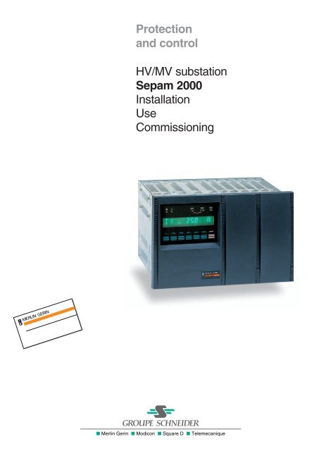
Protectionand controlHV/MV substation<strong>Sepam</strong> <strong>2000</strong>InstallationUseCommissioning
2 HV/MV substation Installation - Use - Commissioning
InstallationEquipment identificationInstallation of <strong>Sepam</strong> <strong>2000</strong>Each <strong>Sepam</strong> <strong>2000</strong> comes in a single packagewhich contains:b <strong>Sepam</strong>,b mounting accessories,b connection accessories (connectors).The other optional accessories come in a separate package.We recommend that you follow the instructions given in this document for quick,correct installation of your <strong>Sepam</strong> <strong>2000</strong>:b equipment identification,b assembly,b connection of current and voltage inputs, temperature sensors,b microswitch setting,b connection of power supply and earth,b checking prior to commissioning.Identification of <strong>Sepam</strong> <strong>2000</strong>Each <strong>Sepam</strong> is identified by a 14-character reference which describes itsequipment and functional components in accordance with the chart below.series model type variant communication number of working current auxiliary operatingESTOR language sensor supply temperatureboardsS26 CC A = Overhead 1 to 99 X = none 0 = 0 F = French C = CS A = 24 Vdc N = -5/55 °CS36 LT B = Busbars J = JBUS 1 = 1 A = English T = CT B = 38/125 VdcKR C = Capacitor 2 = 2 I = Italian C = 220 VdcXR L = Line 3 = 3 E = SpanishYR R = RTULR S = SubstationTR T = TransformerCR U = Underground1/2 HV/MV substation Installation - Use - Commissioning
There are five labels for identifying <strong>Sepam</strong>:b two labels on thr right side panel which givethe product equipment features (1) ,b a label on the front of the cartridge which givesthe functional features (2) ,b a label on the left side of the cartridge which givesthe references (3) ,b a label on the right side of the cartridge which givesthe references of non standard program logicschemes (4) .Example of <strong>Sepam</strong> reference:S36 <strong>Sepam</strong> 2036XRtypeSsubstation62 62Xno communication2 2 ESTOR boardsAEnglishTTCA24 VN -5/+55 °CMERLIN GERINMERLIN GERINequipment upgradinglabelSEPAM <strong>2000</strong>S35/S36 XR *** X2* TAN9641087origin : FRANCEmodelequipment reference(<strong>Sepam</strong>, modeland application)serial no.S36 XR S62 X 2 A TAN 9641087spaces reserved forequipment changese.g. addition of anESTOR boardspaces reserved forafter-sales serviceinterventionse.g; replacement of anECM board(1)Example of labels on right side panelboard nameintervention datesS36 XR S62compatible<strong>Sepam</strong> modelS36 : standard <strong>Sepam</strong>XR : modelS62 : typeprogram logicdiagram reference6 XR S62 AA269 SA Atype of applicationcontrol logic diagramreference6 : <strong>Sepam</strong> S36XR : modelS62 : typeA : EnglishA : rev. level<strong>Sepam</strong> ref. :Proj ref. :Drwg n° :DateVersion(2)Example of label on front of cartridge.Cubicle ID :(4)Label on right side of cartridgeIdentification of non standard program logic03143764FA-B0-01-9740208(3)Example of label on left side of cartridge.HV/MV substation Installation - Use - Commissioning1/3
InstallationEquipment identification (cont’d)Accessories suppliedwith <strong>Sepam</strong> <strong>2000</strong>Each <strong>Sepam</strong> comes with the following accessories.CCA 660 connector for connectionof 1 A or 5 A CTs:b for 4 mm eye lugs,b for max. 6 mm 2 wire (awg 10)or CCA 601 BNC/BNC wire, length 5.5 m.,for connection to CSP sensors.CCA 604 connector4-pin. Connection of power supply:b screw terminals,b 0.6 to 2.5 mm 2 wire(awg 20 to awg 14).CCA 606 connector6-pin. Connection of a core balance CT:b screw terminals,b 0.6 to 2.5 mm 2 wire(awg 20 to awg 14).CCA 608 connector (according to type of <strong>Sepam</strong>)8-pin. Connection of VTs:b screw terminals,b 0.6 to 2.5 mm 2 wire(awg 20 to awg 14).CCA 621 connector21-pin. Connection of logic inputs/outputsand temperature sensors:b screw terminals,b 0.6 to 2.5 mm² wire(awg 20 to awg 14).2 <strong>Sepam</strong> mounting lugs1/4 HV/MV substation Installation - Use - Commissioning
Optional accessoriesTSM 2001 pocket terminalUsed to make <strong>Sepam</strong> <strong>2000</strong> settings. It does not havea battery since it is supplied with power by the<strong>Sepam</strong> <strong>2000</strong>.SFT 2801 kitSoftware tool installed on PC microcomputerwhich may be used instead of the TSM 2001 pocketterminal.It comprises:b a 3"1/2 diskette,b an instruction manual,b a connection kit(ACE 900 adapter + cord).ACE 900 adapter to be connected to the pocket terminal socket.AMT 819 plateUsed to mount <strong>Sepam</strong> <strong>2000</strong> on a 19" rack.266482AMT 820 shieldUsed to block off the space between <strong>Sepam</strong>and the edge of the AMT 819 plate.87HV/MV substation Installation - Use - Commissioning1/5
InstallationEquipment identification (cont’d)Optional Jbuscommunication accessoriesCCA 609 connection box and CCA 802 cable (3 m)Connection to the Jbus communication network.These accessories simplify the wiring of thecommunication network:b the network is connected to the screw terminalsof the CCA 609 box,b the CCA 609 box is mounted on a DIN rail,b the CCA 602 box provides the link btweenthe CCA 609 box and <strong>Sepam</strong>.909 101112 131415161 2 3 4 5 6 7 880CCA 619 chaining connectorConnector used to connect to the Jbus field busby chaining.P1P2CA8A7A6A5A4A3A2A1S1S2microswitch settingutsCCA 600 connector, 9-pin sub D typeUsed to connect the communication network.This is an alternative to using the CCA 609 box andCCA 602 cable.The network wires are to be welded to the connectorterminals.CCA 602 cable3 m long cable with connectors.N.B.For further information, please refer to Jbusdocumentation no. 3140751.1/6 HV/MV substation Installation - Use - Commissioning
InstallationAssembly and wiringDimensions and drillingdrilling diagram<strong>Sepam</strong> <strong>2000</strong> is flush-mounted in a rectangularcut-out.Maximum thickness of mounting: 3 mm.mounting lugs (x 2)<strong>Sepam</strong> A (mm) B (mm) C (mm)222201202S26 * 244 250 264S36 * 332 338 352* S25, S35 for earlier versions20 300BCAAssemblyb insert <strong>Sepam</strong> <strong>2000</strong> through the front of the cut-out.Slide it into the cut-out until the front of <strong>Sepam</strong> <strong>2000</strong>is in contact with the mounting plate. The 2 notches(1) at the base of the <strong>Sepam</strong> <strong>2000</strong> case allowit to hold by its own weight.b position the 2 lugs (2) in the holes on the topof <strong>Sepam</strong>. Tighten the threaded studs of the lug.b make sure not to block the ventilation openingson the top and bottom of <strong>Sepam</strong> <strong>2000</strong>. Leave a spaceof at least 5 cm above and below <strong>Sepam</strong>.(2)(2)(1)HV/MV substation Installation - Use - Commissioning1/7
InstallationAssembly and wiring (cont’d)<strong>Sepam</strong> <strong>2000</strong> componentsslot 1 2 3 4 5 6CE40 ECM (2) ESB ESTOR1 ESTOR2S26 modelLT CE40 ECM 3U/Vo ESB ESTOR ESTORslot 1 2 3 4 5 6 7 8CE40 ECM (2) 3U/Vo ESB ESTOR1 ESTOR2(1) (3)ESTOR3S36 modelXR CE40 ECM_3U/Vo ESB ESTOR ESTOR ESTORLR CE40 ECM ECM 3U/Vo ESB ESTOR ESTOR ESTORKR CE40 ECM ECM_ESB ESTOR ESTOR ESTORYR CE40 ECM__ESB ESTOR ESTOR ESTORTR CE40 ECM 3U/Vo 3U/Vo ESB ESTOR ESTOR ESTORCR CE40 ECMD ECMD_ESB ESTOR ESTOR ESTORCC CE40 ECMD ECMD ECMD ESB ESTOR ESTOR ESTOR(1)the ESTOR board may be installed, depending on the application,(2)or ECA for CSP sensors,(3)option for ESTOR board.* S25, S25 for earlier versions.1/8 HV/MV substation Installation - Use - Commissioning
ConnectionsThe <strong>Sepam</strong> <strong>2000</strong> connections are made on theremovable connectors located on the rear of thedevice. All the connectors are screw-lockable.Wiring of screw connectors:b recommended wire fitting:v Telemecanique DZ5CE0155 for 1.5 mm 2 ,v DZ5C0253 for 2.5 mm 2 .Stripped length with fitting: 17 mm without fitting:b stripped length: 10 to 12 mm,b maximum 2 wires per terminal.21-pin connectors must be plugged in correctlyby hand before locking with the 2 screws provided(top/botton).Terminal identificationprincipleb slots 1 to 8b A or B connectorb terminals 1 to 21.Each connector is used specifically for a Functional assembly identified on the topright according to the function:b CE40: auxiliary power supply and communication option,b ECM: current sensor (CT) interface,b ECA: current sensor (CSP) interface,b 3U/Vo: voltage sensor interface,b ESB: circuit breaker control interface,b ESTOR: auxiliary control circuit interface,The relative position of the assemblies depends on the <strong>Sepam</strong> <strong>2000</strong> model.* S25, S25 for earlier versions.HV/MV substation Installation - Use - Commissioning1/9
InstallationConnection of current inputs to 1 A or 5 A CTsThe current transformer (1 A or 5 A) secondarycircuits are connected to the CCA 660 connectorof the ECM module. This connector contains3 interposing ring CTs with through primaries,which ensure impedance matching and isolationbetween the 1 A or 5 A circuits and <strong>Sepam</strong> <strong>2000</strong>.The connector may be disconnected with the poweron since disconnection does not open the CTsecondary circuits.ESTOR21201918171615141312111098765432124-30 48-125 220-250V-DCAESTOR ESTOR ESB 3U/V0212019181716151413121110987654321A24-30 48-125 220-250V-DC212019181716151413121110987654321A24-30 48-125 220-250V-DC212019181716151413121110987654321A24-30 48-125 220-250V-DC87654321ASW1ECMBSW2SW1B654321AECMBSW2SW1B654321A43 +21ACE40B24-30 48-125 220-250V-DC(communicationoption)87654321INPUTS ANDOUTPUTSINPUTS ANDOUTPUTSINPUTS ANDOUTPUTSINPUTS ANDOUTPUTSVOLTAGEINPUTCURRENTINPUTCURRENTINPUTPOWER SUPPLY1 A or 5 A CT block andconnection diagramECMDPCL1L2L3B4B1B5B2B6B3P1P2<strong>Sepam</strong>current inputsCCA 660or CCA 6501 2 3Selection of SW1 and SW2(microswitches) operatingmodes<strong>Sepam</strong> <strong>2000</strong> has several possible operating modes.The operating mode is selected via microswitcheson the rear of the device. They must be set before<strong>Sepam</strong> <strong>2000</strong> is switched on, i.e. <strong>Sepam</strong> <strong>2000</strong> isde-energized.The microswitches are hidden by the CCA 660connector once it has been installed.N.B. <strong>Sepam</strong> S36, models LR, LS, KR, KZ, CRand CC, have 2 or 3 inputs for connecting CTs.Remember to set the microswitches for the2 or 3 inputs.Microswitch settingSW2for use on the 5 Asecondary circuit.SW2for measuring residualcurrent by the sumof the currents.SW1SW1SW2for use on the 1 Asecondary circuit.SW2for measuring residualcurrent by a corebalance CT.SW1SW11/10 HV/MV substation Installation - Use - Commissioning
CCA 660 connectorb open the 2 side shields for access to theconnection terminals. The shields may be removed, ifnecessary, to facilitate wiring. If removed, replacethem after wiring.b remove the bridging strap, if necessary.The strap links terminals 1, 2 and 3.b connect the wires using 4 mm eye lugs.The connector accommodates wire with crosssectionsof 1.5 to 6 mm 2 (awg 16 to awg 10).b close the side shields.b plug the connector into the 9-pin inlet on the rearof the device. Item B of the ECM module.b tighten the CT connector fastening screwson the rear of <strong>Sepam</strong>.HV/MV substation Installation - Use - Commissioning1/11
InstallationConnection of current inputs to CSPsThe CSP sensors are connected b prefabricatedcoaxial cables, part no. CCA 601,supplied with <strong>Sepam</strong>.The cables are plugged into:b <strong>Sepam</strong> <strong>2000</strong>, in the BNC inlets on the rear of thedevice, identified L1, L2 and L3 of the ECA modules,b the CSP sensors, in the BNC outlet on eachsensor,b the 3 BNC outlets are not equippedwith the plugged detector detection system.CSP connection diagramThe CCA 601 cable shielding is earthed naturallyby the connection to <strong>Sepam</strong> <strong>2000</strong>”s BNC inlets.Do not earth by any other means.The CSP sensors should be earthed via thegrounding screw on the side of the device.ECAL1L2L3CCA 601 cableP1P21 2 3ECAL1P1Detailed viewof a connectionCCA 601 cableP2CSP sensor1/12 HV/MV substation Installation - Use - Commissioning
Selection of SW1 and SW2(microswitches) operatingmodesThe operating mode is selected by settingthe microswitches on the rear of the device.They must be set before <strong>Sepam</strong> <strong>2000</strong> is switched on,while it is de-energized.Set microswitches SW1 and SW2 in accordancewith he chart opposite. They are to be setaccording to:b the CSP model used (30 A-300 A, 160 A-1600 A,500 A-2500 A),b the rated current of the protected installation,b the earth fault current measurement method(sum or core balance CT).N.B. When the rated current of the electricalinstallation to be protected does not appearin the chart, choose the column that correspondsto the current rating immediately above.Example of microswitch settingThis example indicates the microswitch settingin the following case:b network rated current: 160 A,b CSP sensor used: model 160-1600 A,b residual current measured by the sumof the 3 phase currents.Microswitch setting chartCSP 31-10: 30 to 300 A30 36 45 60 75 90 120 150 180 225 300CSP 32-10: 160 to 640 and CSP 33-10: 160 to 1600 A160 192 240 320 400 480 640 800 960 1200 1600CSP 34-10: 500 to 2500 A500 600 750 1000 1250 1500 <strong>2000</strong> 2500SW2 : for selection of the phase current range0 1 0 1 0 1 0 1 0 1 0 1 0 1 0 1 0 1 0 1 0 10 11phase 167SW1: residual current by the sum of the 3 phase currentsSOM 1 SOM 20 1 0 1 0 1 0 1 0 1 0 1 0 10 1 0 10 10 1phase 2phase 31213SW2SW1: residual current measured by core balance CT0 1 0 1 0 1 0 1 0 1 0 1 0 1 0 10 10 10 11812 SW1SOM 1 and SOM 2 are parameters to be set in the status menu of the pocket terminal.HV/MV substation Installation - Use - Commissioning1/13
InstallationUse of CSH 120 and CSH 200 core balance CTsThe only difference between the CSH 120 and CSH200 core balance CTs is their inner diameter(120 mm and 200 mm). Due to their low voltageisolation, they may only be used on cables.Mounting directionIt is imperative to comply with the mounting directionof the core balance CTs in order for the protectionsto work correctly. The core balance CTs should bemounted with the printed side of the CT (P2 side)on the cable side and the unmarked side (P1 side)on the busbar side. Core balance terminal 2 is alwaysconnected to terminal A4 of the 6-pin connector.CSH 120 and CSH 200connection diagramTo measure residual current up to 20 A, connectthe core balance CT to the «2A rating» input.To measure residual current up to 300 A, connectthe core balance CT to the «30A rating» input.ECA/ECMDPCREFcalib. 30 Acalib. 2 ATC toreAA6A5A4A3A2A1S2S1P1P2S2P1CSH core balance CT1 2 3S1P2earthed metalliccable sheldingSelection of operating modes(microswitches)b Set the corresponding <strong>Sepam</strong> <strong>2000</strong> switches.The switches concerned are found on the inputmodule.Refer to the chapter entitled «connection of currentinputs», «selection of operating modes».1 2 3cable shield earthing1/14 HV/MV substation Installation - Use - Commissioning
AssemblyAssembly on MV cables.Assembly on mounting plate.Group the MV cable (or cables) in the middleof the core balance CT. Use non-conductive bindingto hold the cable.Remember to insert the 3 medium volage cableshielding earthing cables through the corebalance CT.CablingThe CSH 120 or CSH 200 core balance CTis connected to the CCA 606 6-pin connector (item B)of the current input module.Recommended cable:b sheathed, shielded cable,b min. cable cross-section 0.93 mm 2 (awg 18),b resistance per unit length < 100 mΩ/m,b min. dielectric strength: 1000 V.Connect the connector cable shielding in the shortestmanner possible to the <strong>Sepam</strong> <strong>2000</strong> 6-pin connector.Flatten the connection cable shielding against themetal frames of the cubicle.The cable shielding is grounded in <strong>Sepam</strong> <strong>2000</strong>.Do not ground the cable by any other means.HV/MV substation Installation - Use - Commissioning1/15
InstallationUse of the CSH 30 interposing ring CTThe CSH 30 interposing ring CT should be used whenresidual current is measured by a current transformerwith a secondary circuit (1 A or 5 A).It acts as an interface between the currenttransformer and the <strong>Sepam</strong> residual current input.The CSH 30 interposing ring CT is mountedon a symmetric DIN rail. It may also be mountedon a plate by means of the mounting holes in its base.AssemblyThe cable must pass through the CSH 30 in the rightdirection in order for directional earth fault protectionto function correctly: the cable leaving the S2terminal of the current transformer should enterthrough the P2 side of the CSH 30 interposing ringCT.CablingThe secondary winding of the CSH 30 is connectedto the 6-pin connector of the CCA 606.Cable to be used:b sheathed, shielded cable,b min. cable cross-section 0.93 mm 2 (awg 18)(max. 2.5 mm 2 ),b resistance per unit length < 100 mΩ/m,b min. dielectric strength: 1000 V.Connect the CSH 30 interposing ring CT connectorcable shielding in the shortest manner possibleto the <strong>Sepam</strong> <strong>2000</strong> 6-pin connector.Flatten the connection cable shielding againstthe metal frames of the cubicle.The cable shielding is grounded in <strong>Sepam</strong> <strong>2000</strong>.Do not ground the cable by any other means.1/16 HV/MV substation Installation - Use - Commissioning
Connectionto 1 A secondary circuitb plug into the CCA 606 connector.b wind the transformer secondary wire 5 timesaround the CSH 30 interposing ring CT.ECA/ECMDPCREFcalib. 30 Acalib. 2 Acb CTA6A5A4A3A2A1CSH 30core balance CTS2S15 turnsP1 S1P2S21 A CT1 2 3P1P2Connectionto 5 A secondary circuitb plug into the CCA 606 connector.b wind the transformer secondary wire just oncearound the CSH 30 interposing ring CT.ECA/ECMDPCREFcalib. 30 Acalib. 2 Acb CTA6A5A4A3A2A1CSH 30core balance CTS2S11 turnP1 S1P2S25 A CT1 2 3P1P2Selection of operating modes(microswitches)Set the microswitches, referring to the chapter entitled«connection of current inputs»,«selection of operating modes».HV/MV substation Installation - Use - Commissioning1/17
InstallationConnection of voltage inputsThis concerns types of <strong>Sepam</strong> <strong>2000</strong> which havevoltage inputs.Types S26* LT.S36* XR, LR, TR.The phase and residual voltage transformers (VTs)are connected to the CCA 8-point connector of the3U/Vo module. <strong>Sepam</strong> <strong>2000</strong> can function with 1, 2or 3 VTs.Residual voltage can be measured by two methods:b calculated by <strong>Sepam</strong> <strong>2000</strong> based on the phasevoltages,b wired directly to <strong>Sepam</strong> <strong>2000</strong> from a transformerwith open delta-star windings.SW1 microswitch setting:The microswitches are set, with <strong>Sepam</strong> de-energized,according to the chosen connection diagram.N.B. <strong>Sepam</strong> S36, TR model, have 2 inputs forconnecting VTs.Remember to set the microswitches for both inputs.ESTOR212019181716151413121110987654321824-30 48-125 220-250V-DCAINPUTS ANDOUTPUTSESTOR ESTOR ESB 3U/V0212019181716151413121110987654321A724-30 48-125 220-250V-DCINPUTS ANDOUTPUTS212019181716151413121110987654321A624-30 48-125 220-250V-DCINPUTS ANDOUTPUTS212019181716151413121110987654321A524-30 48-125 220-250V-DCINPUTS ANDOUTPUTS487654321ASW1VOLTAGEINPUTECMBSW2SW1B654321A3CURRENTINPUTECMBSW2SW1B654321A2CURRENTINPUT43 +21ACE40B24-30 48-125 220-250V-DC1POWER SUPPLY(communicationoption)Connection of 3 VTsThis arrangement does not allow residual voltagemeasurement by the sum of the 3 phase voltages.123P1P2or3U/V0U21U32U13V2DPCSW1voltage inputsA8A7A6A5A4A3A2A1S1S2microswitch settingConnection of 3 VTs(residual voltagemeasurement)This arrangement enables <strong>Sepam</strong> <strong>2000</strong> to measurethe system voltages and calculate the residual voltagebased on the VT secondary voltages.It requires the uses of 3 VTs with the primary betweenphase and earth.Terminals 1 and 6 must be strapped in order for<strong>Sepam</strong> to calculate the residual voltage.1233U/V0U21U32U13V2DPCSW1A8A7A6A5A4A3A2A1P1S1microswitch settingP2S2voltage inputs1/18 HV/MV substation Installation - Use - Commissioning
Connection of 2 VTsThis arrangement does not allow residual voltageto be measured by the sum.123P1P2or3U/V0U21U32U13V2DPCSW1A8A7A6A5A4A3A2A1S1S2microswitch settingvoltage inputsConnection of 1 VTThis arrangement does not allow residual voltageto be measured by the sum.123P1P2or3U/V0U21U32U13V2DPCSW1A8A7A6A5A4A3A2A1S1S2microswitch settingvoltage inputsConnectionof residual voltage input123This arrangement is used to connect the residualvoltage measured outside <strong>Sepam</strong> <strong>2000</strong> viaa transformer with open delta-star windings.The connection is made to terminals A1 and A2of the 8-pin connector.3U/V0U21U32U13V2DPCA8A7A6A5A4A3A2A1P1S1P2S2SW1microswitch settingvoltage inputsHV/MV substation Installation - Use - Commissioning1/19
InstallationConnection of voltage inputs (cont’d)Connectionof 2 system voltages(synchro-check function)123The connections are made so that the voltagesapplied to inputs 5 and 4 (Usync1) and 2 &nd 1(Usync2) correspond to the same phases.example : U21U’213U/V0U21U32U13V2DPCSW1A8A7A6A5A4A3A2A1microswitch settingvoltage inputsConnectionof 2 phase voltages(synchro-check function)The connections are made so that the voltagesapplied to inputs 5 and 4 (Usync1) and 2 &nd 1(Usync2) correspond to th same phases.example : V1V’13U/V0U21U32U13V2DPCSW1A8A7A6A5A4A3A2A1microswitch settingvoltage inputsV-connection of 3 VTs or 2VTs (synchro-check function)123The connections are made so that the voltagesapplied to inputs 5 and 4 (Usync1) and 2 &nd 1(Usync2) correspond to th same phases.V1, V2, V3 or U21, U32 and U21This arrangement enables <strong>Sepam</strong> <strong>2000</strong> to measurevoltage and power.3U/V0U21U32U13V2DPCSW1A8A7A6A5A4A3A2A1microswitch settingvoltage inputs1/20 HV/MV substation Installation - Use - Commissioning
InstallationConnection of power supply and logic inputs and outputsConnectionof power supplyand earthThe <strong>Sepam</strong> <strong>2000</strong> power supply is connected to theCCA 604 4-pin connector on the CE40 modulesituated on the rear of the device. The power supplyinput is protected against accidental polarityinversion.Safety:The <strong>Sepam</strong> <strong>2000</strong> chassis must beearthed via the grounding screw situatedon the right side panel (rear view).Use a braid or cable fitted with a 4 mm eye lug.The eye lug fastening screw is already mounted on<strong>Sepam</strong> when it is delivered. (Should this screw belost, never replace it by a screw longer than 8 mm).ESTOR212019181716151413121110987654321824-30 48-125 220-250V-DCAINPUTS ANDOUTPUTSESTOR ESTOR ESB 3U/V0212019181716151413121110987654321A724-30 48-125 220-250V-DCINPUTS ANDOUTPUTS212019181716151413121110987654321A624-30 48-125 220-250V-DCINPUTS ANDOUTPUTS212019181716151413121110987654321A524-30 48-125 220-250V-DCINPUTS ANDOUTPUTS87654321A4SW1VOLTAGEINPUTECMBSW2SW1B654321A3CURRENTINPUTECMBSW2SW1B654321A2CURRENTINPUT43 +21ACE40B24-30 48-125 220-250V-DC1POWER SUPPLY(communicationoption)Connectionof logic inputs and outputsThe logic data are connected to the CCA 621connector on the ESB and ESTOR modules.Cabling should be done in accordancewith the diagram for your application.ESTORl18l17l16l15l14l13O14O13O12O11l12l11DPCAA21A20A19A18A17A16A15A14A13A12A11A10A9A8A7A6A5A4A3A2A1ESBCDGO2O1l2l1DPCAA21A20A19A18A17A16A15A14A13A12A11A10A9A8A7A6A5A4A3A2A1ESTOR212019181716151413121110987654321824-30 48-125 220-250V-DCAINPUTS ANDOUTPUTSESTOR ESTOR ESB 3U/V0212019181716151413121110987654321A724-30 48-125 220-250V-DCINPUTS ANDOUTPUTS212019181716151413121110987654321A624-30 48-125 220-250V-DCINPUTS ANDOUTPUTS212019181716151413121110987654321A524-30 48-125 220-250V-DCINPUTS ANDOUTPUTS487654321ASW1VOLTAGEINPUTECMBSW2SW1B654321A3CURRENTINPUTECMBSW2SW1B654321A2CURRENTINPUT43 +21ACE40B24-30 48-125 220-250V-DC1POWER SUPPLYCheck that the voltage applied to the inputs is compatible with the voltageindication given on a dot on the subassembly.(communicationoption)Example: ESTOR 1 and ESB.HV/MV substation Installation - Use - Commissioning1/21
InstallationConnection of the Jbus communication coupler<strong>Sepam</strong> <strong>2000</strong> can be equipped, as an option,with a communication coupler situated on the CE40module.Please refer to the «<strong>Sepam</strong> <strong>2000</strong>, Jbuscommunication» document for instructionson commissioning.A CCA 602 cable (option), 3 meters long, fittedwith a 9-pin connector at either end, may be usedto connect the coupler directly to the CCA 609network connection box (option).This box allows quick connection to the Jbus networkand ensures all earthing required for safe operation.ESTOR21201918171615141312111098765432124-30 48-125 220-250V-DCAESTOR ESTOR ESB 3U/V0212019181716151413121110987654321A24-30 48-125 220-250V-DC212019181716151413121110987654321A24-30 48-125 220-250V-DC212019181716151413121110987654321A24-30 48-125 220-250V-DC87654321ASW1ECMBSW2SW1B654321AECMBSW2SW1B654321A43 +21ACE40B24-30 48-125 220-250V-DC(communicationoption)87654321INPUTS ANDOUTPUTSINPUTS ANDOUTPUTSINPUTS ANDOUTPUTSINPUTS ANDOUTPUTSVOLTAGEINPUTCURRENTINPUTCURRENTINPUTPOWER SUPPLY1/22 HV/MV substation Installation - Use - Commissioning
Use - commissioningContentschapter / pageuse - commissioning 2/1description / use 2/2front face 2/2TSM 2001 pocket terminal 2/4use (current operation) 2/6energizing 2/6operation via the front face or pocket terminal TSM 2001 or the PC 2/6operation via the pocket terminal only 2/7annunciation 2/8list of messages 2/8commissioning 2/10checking prior to commissioning 2/10commissioning 2/10parameter and setting errors 2/11status menu parameter chart 2/11SW1 and SW2 microswitch settings 2/12protections 2/12protection function setting ranges 2/14program logic and annunciation 2/18resources and program logic chart 2/18connection of logic inputs 2/19connection of logic outputs 2/22parameter setting… 2/24time delay settings… 2/25operation… 2/35disturbance recording 2/41remote setting 2/41maintenance 2/42indicator lamps and display messages 2/42unwanted tripping, no tripping 2/43tests 2/43<strong>Sepam</strong> replacement 2/43<strong>Sepam</strong> identification using the pocket terminal 2/44compatibility of types and models 2/45<strong>Sepam</strong> documentation 2/46password 2/47use of the password 2/47modification of the password 2/47testing a <strong>Sepam</strong> 2/48procedure 2/48setting record sheets 3/1HV/MV substation Installation - Use - Commissioning2/1
Use - commissioningDescription / useYour <strong>Sepam</strong> <strong>2000</strong> is a multifunction, microprocessorbased device which includes, in the same case:b control and monitoring of the associated circuitbreaker or contactor,b measurement of electrical variables,b display of operating messages,b protection of the network and the machinesit supplies.<strong>Sepam</strong> <strong>2000</strong> may be equipped (as an option)with a communication link with the remote monitoringstation.There are two models of <strong>Sepam</strong>.Front face123onI on O off tripA V/Hz W/ϕ Wh clear alarm resetMERLIN GERINS35XRS0553XRS05FA101SFB41 status indicators2 display3 keys for access to measurements and alarm processing4 cartridge5 pocket terminal socketStandard model: <strong>Sepam</strong> <strong>2000</strong> S36 (for all types)Status indicators 1 :b green on indicator lamp shows that <strong>Sepam</strong> <strong>2000</strong> is energized,b red trip indicator lamp: <strong>Sepam</strong> has tripped the circuit breaker after detectinga fault. A related alarm message indicates the cause of tripping.b red indicator lamp shows internal <strong>Sepam</strong> faults. All the output relays aredropped out (fail-safe position). Refer to the chapter on maintenance.b yellow I on / green O off indicator lamps show the position of the circuitbreaker:v I = circuit breaker closed,v O = circuit breaker open.Compact model: <strong>Sepam</strong> <strong>2000</strong> S26 (for certain types)2/2 HV/MV substation Installation - Use - Commissioning
Display 2The display unit indicates:b measurements,b operating messages.Keys for access to measurements and alarmprocessing 3b metering keyThe measurements may be accessed by pressingthe A, V/Hz, W/j, Wh/°C metering keys.Each key provides access to a set ofmeasurements according to the following method:v reset key:the protections trigger circuit breaker tripping and display of the related messages.The red trip indicator lights up.After the fault has been cleared, the user presses the reset key to acknowledge.The trip indicator is extinguished, the lists of alarms is erased and the device canbe closed. The reset key is disabled until the fault has been cleared.I1key- A -TRIP0I2statusTRIP3I3onI onO offtripTRIP2IM1indicators 1 2displayTRIP1IM3IM2AV/Hz W/ϕ Wh/°C clear alarmresetExample: current measurementkeys3When a measurement is not available in a typeof <strong>Sepam</strong>, ----------- is displayed.b clear key:this key erases the stored value being displayed(reset):- maximum demand current IM1, IM2, IM3,- tripping currents TRIP1, TRIP2, TRIP3, TRIP0,- peak demand voltage PM, QM;b alarm processing keyv alarm key:each time tripping or another event occurs, an alarmmessage appears on the display.This key provides access to step by step readingof the list of stored alarm messages.The previous message may be displayed bypressing this key.Display of: ----------- indicates the end of the listof alarm messages.Cartridge 4The cartridge contains the information required for <strong>Sepam</strong> operation, such as:b settings,b stored data,b control and monitoring logic...Pocket terminal socket 5This socket is used to connect the TSM 2001 pocket terminal or the ACE 900adapter to the SFT 2801 bit (PC link).HV/MV substation Installation - Use - Commissioning2/3
Use - commissioningDescription / use (cont’d)TSM 2001 pocket terminalYour pocket terminal provides accessto all the <strong>Sepam</strong> <strong>2000</strong> information, such as:b current measurements,b operating assistance messages,b protection settings.Role of the keys:b the pocket terminal beeps when the user presses a key that is disabled.b the menu key is used to display the previous menu,b the ! and " keys are used to move the b cursor one line up or down in amenu.To move to the next screen of a menu, the user simply positions the cursor onthe last line and presses the " key.MERLIN GERINTSM 2001S e l e c tM e t e r i n gP r o t e c t i o n sP r o g r a m l o g i c13P/Select:MeteringProtectionProgram logicmenu784512. 0clear -codedata963units+enter2P/Select:Add. readingStatusAbout <strong>Sepam</strong>1 4-line display2 data entry keypad3 brightness adjustment dialThe pocket terminal is supplied with power by <strong>Sepam</strong>and does not require any batteries; it can beconnected with the power on.The pocket terminal beeps when it is connected.The main menu appears (if nothing is displayed,adjust the brightness using the dial 3 ).The user may access the various data from threemenu levels. A menu may comprise several pages.To access a menu, simply position the blinking cursoron the desired line and press the enter key.The first line of the menu contains the name of thecurrent menu or function.When P/ appears at the top of the menu, it meansthat the user has entered the password.To move to the previous screen of a menu, the user simply positions the cursoron the second line and presses the ! key.b the code key is used to enter and exit the parameter setting mode,b the numeric and . keys are used to enter settings and the password,b the units key is used to change setting unit multiplying factors (e.g. A, kA, ...),b the data+ and data- keys are used to select values from preset data lists.These lists are used when only a limited number of values may be usedfor a parameter, e.g. network frequency.b the clear key is used to:v clear error messages,v call back a previous setting value during data input,v reset tripping currents and maximum demand readings,b the enter key is used to confirm a menu selection or to confirm all the settingsfor a function.N.B. The first line always contains the name of the current menu or function.2/4 HV/MV substation Installation - Use - Commissioning
MenuEnterP/Select:MeteringProtectionProgram logicEnterP/Select:Add. readingStatusAbout <strong>Sepam</strong>MenuMenu Menu Menu Menu MenuP/ABOUT...SFT 2800Program logicCommunicationP/STATUSRated frequencyPhase CT ratioE/F SensorP/ADD. READINGResidual IResidual VI and V startP/PROGRAM LOGICLogic inputLogic outputMonostable relayP/PROTECTIONOvercurrent/S1 F011Earth fault/S1 F081Thermal F431P/METERINGPhase currentSystem voltagePower & pwr factorEnterEnterEnterEnterEnterEnterMenuMenuMenuMenuMenuMenuP/PROGRAM LOGIC269SFA LDR CATHV/MV SUBSTATIONSUBSTATIONP/PHASE CT RATIOIn = 500 AIb = 450 ANumber = I1-I2-I3P/I RESIDUAL CURRENTI0 = 12.3 AP/LOGIC OUTPUT01-02 = 10011-014 = 0000021-024 = 1010P/OVERCURRENT/S1 F011Curve = DefiniteIs = 1,2 kAT = 300 msP/I PHASE CURRENTI1 = 453 AI2 = 452 AI3 = 453 AMERLIN GERINTSM 2001SelectMeteringProtectionProgram logicmenu784512. 0clear -codedata963units+enterHV/MV substation Installation - Use - Commissioning2/5
Use - commissioningUse (current operation)Energizing<strong>Sepam</strong> is energized when operating normally.In the event of re-energizing after a break in theauxiliary power supply, <strong>Sepam</strong> <strong>2000</strong> automaticallyrestarts according to the following sequence, whichlasts about 5 s:b green on and red indicators light up,b beep (if the pocket terminal is connected),b extinction of the red indicator,b setting of the watchdog contact,b testing of display:0,0,0,0,0,0,0,0,0,0,0 then ***********, then I1 = 0.0 A,b breaker position indicator lights up,b display of the first message. <strong>Sepam</strong> is then in operation.If the pocket terminal is connected, it displays:Pressmenu keyto accessopening menuOperation via the front face or pocket terminal TSM 2001 or the PCfunctions key TSM 2001 menu name description range accuracy commentsphase current A metering I1 measurement of 0 to 24 In +0.5% value depends onI2 each phase current associated CTI3max. demand A metering IM1 measurement of the 0 to 24 In +0.5% the value is periodicallycurrent IM2 average current in recalculated. ValueIM3 the 3 phases set in Status menu to5, 10, 15, 30 or 60 mnRESET: clear keytripping A metering TRIP1 measurement of 0 to 24 In +5% RESET: clear keyTRIP2 phase and earthTRIP3 currents at theTRIP 0 time of tripping 0 to 10 Inovoltage V/Hz metering U21 measurement of 0 to 375 kV +0.5% value depends onU32 system voltages associated VTU13frequency V/Hz metering F measurement of 45 to 65 Hz +0.02 Hz measured onfrequencyU21 inputreal power W/ϕ metering P measurement of 0 to 999 MW +1% positive or negativereal powerreactive power W/ϕ metering Q measurement of 0 to 999 MVAR 1% positive or negativereactive powerpower factor W/ϕ metering COS measurement of -1 to +1 0.01 P sign inductive orpower factorcapacitivepeak demand W/ϕ metering PM measurement of the 0 to 999 MW +1% same comment asreal and reactive greatest average for max. demandpower W/ϕ metering QM power value 0 to 999 MVAR +1% currentsWh/°c metering +MWH measurement of 0 to 99999.99 +1% for displayreal andreal energy consumedreactive Wh/°C metering +MVRH measurement ofenergyreactive energy consumedWh/°C metering -MWH measurement of 0 to 280x10 6 +1% for the pocketreal energy suppliedterminalWh/°C metering -MVRH measurement of values are stored in thereactive energy suppliedevent of a power failureN.B. No value is displayed when the measurement is less than 1.5% of the nominal value.<strong>Sepam</strong> <strong>2000</strong> performs the functions of a precision measurement and alarmprocessing unit. The values are displayed directed with the related unit A, kA, etc.The messages clearly worded. There are two ways of operating the device:b via the front face (metering, annunciation keys),b via the TSM 2001 pocket terminals or PC (using menu).Whenever a measurement is not available in the user’s type of <strong>Sepam</strong>----------- is displayed.2/6 HV/MV substation Installation - Use - Commissioning
Operation via the pocket terminal onlyfunction TSM 2001 menu name description range accuracyearth fault add. reading Io measurement of residual current 0 to 10 Ino +5%residual currentresidual voltage add. reading Vo measurement of residual voltage 0 to 1.5 Un +5%residual voltagethermal overload thermal protection E thermal capacity used 0 to 999% +2%directional directional O/C Phi 1 phase shift between I1 and I32 0° to 360° +3° at In, Unovercurrent protection Phi 3 phase shift between I3 and U21 0° to 360° +3° at In, Undirectional earth directional E/F protection Phi 0 phase shift between Io and Vo 0° to 360° +3°faultcumulative breaking add. reading cumulative (kA) 2 broken by 5% In to 24 In +10%current and nb. of nb of (kA) 2 breaks breaking current rangebreaksdifferential current add. reading I diff and I through 0 to 24 In +5%and through currenttrue rms current add. reading I rms true rms current up to 0 to 4 In +1%harmonic 21messages program logic AL list of last 16 automation messages 16 messagesevents counter <strong>Sepam</strong> HV Resetline busbar transformerprotection tripping C2 C2 C2 KP49single-phase reclosing C3 KP573-phase reclosing C4 KP57events counter <strong>Sepam</strong> MV Resetsubstation overhead underground capacitor busbardevice switching C1 C1 C1 C1 C1 KP53overcurrent trip C2 C2 C2 C2 C2 KP49fault trip C3 C3 C3 C3 C3 KP49successful reclosing C4 KP54cycle 1 C5 KP54cycle 2 C6 KP54cycle 3 C7 KP54cycle 4 C8 KP54hours counter capacitor <strong>Sepam</strong> Resetcapacitor 1 C4 KP62capacitor 2 C5 KP62capacitor 3 C6 KP62HV/MV substation Installation - Use - Commissioning2/7
Use - commissioningUse (current operation) (cont’d)Clearing measurements:b maximum phase current demand.To reset to zero:v press clear on the pocket terminal if the maximumcurrent demand readings are displayed,v press clear on the display if at least one maximumdemand is displayed,b tripping current (phase or earth).To reset to zero:v press clear on the pocket terminal if all the trippingcurrents are displayed,v press clear on the display if at least one trippingcurrent is displayed,b maximum real and reactive power demands.To reset to zero:v press clear on the pocket terminal if allthe maximum demands are displayed,v press clear on the display if at least one maximumpower demand is displayed,N.B.Zero resetting of the maximum demand readingsallows calculations to be started for a newintegration interval.To reset to zero, press the clear key on the pocketterminal if the heat rise measurement is displayedand if the user is in parameter setting mode, theresetting of this setting alters the normal operationof the protections (changes their prior status).AnnunciationWhen an event is detected by <strong>Sepam</strong>, an operatingmessage appears on the display.The messages are stored in a list of alarms and maybe reviewed in chronological order of appearance,starting with the most recent, by pressing thealarm key.Beware:pressing the reset key will erase the contentsof any list of alarms.List of messages (according to type of <strong>Sepam</strong>)message (1) type meaningADJACENT A tripping of adjacent breakersABSENCE U A line voltage absentBUCHHOLZ P Buccholz trippingCONNECTOR M unplugged connector (DPC)CYCLE 1 A cycle 1 in progressCYCLE 2 A cycle 2 in progressCYCLE 3 A cycle 3 in progressCYCLE 4 A cycle 4 in progressEXT. TRIP A tripping by external protectionDEFINITIVE A definitive tripping (fault not cleared)DISCHARGE A time-delayed energizing?CONTROL? A control monitoringFAULT SSL A logic discrimination faultSHUNT-TRIP P&T circuit breaker with shunt-trip coilU/V RELEASE P&T circuit breaker with undervoltage releaseVT FUSES P neutral voltage displacementUNBAL. AL1 P unbalance capacitor 1 alarmUNBAL. TRIP1 P unbalance capacitor 1 trippingUNBAL. AL2 P unbalance capacitor 2 alarmUNBAL. TRIP2 P unbalance capacitor 2 trippingUNBAL. AL3 P unbalance capacitor 3 alarmUNBAL. TRIP3 P unbalance capacitor 3 trippingFRAME LEAK P tank earth leakageOVERVOLT. P overvoltageO/V BB1 P overvoltage busbar 1O/V BB2 P overvoltage busbar 2OVERVOLT. 1 P overvoltage set point 1OVERVOLT. 2 P overvoltage set point 2N VOLT DISP P neutral voltage displacementOVERCURRENT P phase overcurrentDIR. O/C P directional phase overcurrentNEUTR. O/C1 P neutral set point 1NEUTR. O/C2 P neutral set point 2EARTH FAULT P earth faultDIR. E/F P directional earth faultMEM. OPG A disturbance recording offU/V BB1 P undervoltage busbar 1U/V BB2 P undervoltage busbar 2UNDERFREQ. P underfrequencyUNDERVOLT. P undervoltagePRESSURE A breaking pole pressure faultRECEIVE BI A blocking inputRETRIP A retrippingDEAD ZONEdead zoneRECLOSE A reclosing1PH OR 3PH2/8 HV/MV substation Installation - Use - Commissioning
message (1) type meaningSUCCESSFUL A reclosing successfulSYNCHRO. P synchronizationOVERPRESSURE P overpressureWINDING T P tripping - winding temperatureOIL T P tripping - oil temperatureTHERMAL P thermal overload alarm or trippingVT P VT faultRECL.. LOCKED A recloser locked outMAINTENANCE M <strong>Sepam</strong> internal faultCARTRIDGE M cartridge and <strong>Sepam</strong> not compatibleM. CARTRIDGE M faulty cartridgetypeA = automation (program logic)P = protectionM = maintenanceP&T = control function parameter setting test(1)If your <strong>Sepam</strong> has been customized, other messages may appear. Please refer to theinformation package provided by your installer.HV/MV substation Installation - Use - Commissioning2/9
Use - commissioningCommissioning (cont’d)Checking priorto commissioningThese operations must be carried out before<strong>Sepam</strong> <strong>2000</strong> is energized.Checks:b supply voltageEnsure that the cubicle auxiliary supply voltagematches <strong>Sepam</strong> <strong>2000</strong>”s operating voltage.It is indicated on the rear of the device, beside thepower supply connector, by a dot in the voltage box,ExampleS26LT on the cartridgelabel should matchS26LT on the <strong>Sepam</strong>label.b connectorsCheck that all theconnectors arecorrectly connected tothe rearof the deviceand screw-locked.MERLIN GERINS26 LT A644LTA64FA268AFAMERLIN GERINSEPAM 2026S26 LT J2 TBN*** *4321A+24-30 48-125 220-250V-DCb earthingCheck that the <strong>Sepam</strong> <strong>2000</strong> chassis is earthed bythe ground nut situated on the <strong>Sepam</strong> side panel,on the power supply side.b cartridgev Check that the cartridge is in its slot behind thefront wicket door. To do so, open the wicket door bypulling on the notch situated on the left side panel.<strong>Sepam</strong> S36 and S35 have a shield.on the right,which resembles the memory cartridge wicket door.This shield is not another wicket door. Do not tryto open it. Check that the cartridge has beeninserted correctly. Check the tightening of the 2threaded screws by hand.Above all do not insert or remove the cartridgewhen <strong>Sepam</strong> <strong>2000</strong> is energized,v the cartridge has an identification label on the front.The first 5 characters in the first line indicate the<strong>Sepam</strong> <strong>2000</strong> model. Ensure that this model matchesthe <strong>Sepam</strong> model indicated on the side of <strong>Sepam</strong>.Setting of microswitches on the rear of thedeviceCheck that the microswitches.which defineoperating modes and <strong>Sepam</strong> <strong>2000</strong> calibrationoperations were correctly set at the time ofinstallation (1) .The microswitches must be set with <strong>Sepam</strong>de-energized.If the microswitches are incorrectly set,the measurements given by <strong>Sepam</strong> <strong>2000</strong> will beerroneous and the protections will fail to tripat the desired set points.Default parameter settingFactory-set parameter status:b microswitches:v they are set for a 5 A secondary current power supply,v residual current measurement by core balance CT,v residual voltage measurement by the sum of the 3 voltages,b protection:v set points: 999 kA or kV,v time delays: 655 s,b program logic time delay:v t = 200 ms,CommissioningSwitch on the <strong>Sepam</strong>After the <strong>Sepam</strong> has started up, check that no messages are present bypressing the “alarm” key.Checking modeAll the data may be accessed for checking purposes without the risk of changingparameters or settings.Parameter setting mode (2)This mode is reserved for commissioning and maintenance.The entry of a password is required.P\ appears at the top left of the screen (3) .(1)Refer to chapter 3 «Installation».(2)All parameters and settings must be based on a network discrimination study that isto be carried out prior to commissioning.(3)This mode is automatically cancelled if no keys are pressed for about 1 minute.It may be cancelled manually by pressing the Code key.212019181716151413121110987654321ABSW2SW1654321BA4321A+B24-30 48-125 220-250V-DC2/10 HV/MV substation Installation - Use - Commissioning
Parameter and setting errorsChanging a status parameter may put a protectionsetting outside the tolerance range.<strong>Sepam</strong> detects the problem and displays the followingmessage:P\CT ratioprotection settingout of rangepress clear keyThe user should then check and, if necessary, changethe protection settings. The PROTECTION line blinksuntil the settings have been corrected.Settings out of range.A protection value may be out of range when it is set.<strong>Sepam</strong> detects this and indicates the permissiblerange of settings.P\Earth fault/S1 F081Iso out of range0.05Ino < Iso < InoPress clear keyExample: 50N, 51N earth protection.All the parameters and settings are accessiblein 3 menus:v general parameters: status menu,v protection: protection menu,v operating parameters: program logic menu,General parametersThe general parameters are accessible in the statusmenu; they are to be set at the time of commissioningand must not be modified during current operation.HV/MV substation Installation - Use - CommissioningStatus menu parameter chartheading name function command selectionfrequency Fn network frequency data + and - 50 or 60 HzPhase CT In CT rating numeric adjustable fromratio keys 10 A to 6250 Aphase CT' Ib basis current of numeric 0.4 to 1.3Inratio equip. being protected keys in ampsnumber number of current data + and - 2 or 3 sensorssensorsphase CT In CT rating (standard data + and - 30 values betweenratio for CSP values see table on 30 A and 2500 Athe next page)Ib basic current of the numeric 0.4In to 1.3Inequipment being protected keys in amperesnumber number of data + and - 2 or 3 sensorscurrent sensorsIo sensor Ino residual current data + and - TC:I'o sensor measurement b sum of 3ICPS:b sum1 3Ior sum2 3Ib 2 A or 30 A corebalance CTS26, S36 b CT + CSH30numeric Ino adjustable fromkeys 1 A to 6250 AS25, S35 b 56 values fromdata + and - 1 A to 6250 Amax. period max. demand integration data + and - adjustable from:interval period 5, 10, 15, 30, 60 mnphase VT number number of VTs wirred data + and - S26-S36 S25-S35phase VT’ V U211U U21-U323U 3UUnp rated VT primary numeric adjustable fromvoltage keys 220 V to 250 kVUns rated VT secondary data + and - 100, 110, 115,voltage120 VVnso type of residual data + and - b sum of 3Vstvoltage measurement b Uns / 3b Uns / 3direction of incomer reverses the signs data + and - incomer:energy feeder of power and energy cable --> busbars (1)measurementsfeeder:busbars --> cable (1)communi- speed transmission speed data + and - 300, 600, 1200,cation (2) 2400, 4800, 9600,19200, 38400 bdsstation number of <strong>Sepam</strong>s in numeric 1 to 255the networkkeysparity transmission format data + and - even, odd,without paritytime synchro type of synchronization data + and - via:tagging (2) used - network- inputs I11 or I21(3)events I1 I2 numericI11 to I18keysI21 to I28I31 to I38KTS1 to KTS32 by network 8 bitsKTS33 to KTS64 for S26, S36onlypasswordsee correspondingpage(1)incomer + , feeder +(2)for commissioning, refer to “communication” document.(3)0 = not time-tagged1 = time-tagged.All events are set to zero by default.2/11
Use - commissioningCommissioning (cont’d)MicroswitchSW1 and SW2 settingsThe microswitch settings must be coherent with thechoices made in the status, phase CT ratio and VTratio menus:b phase current input for 1 A / 5 A CT1 A secondary 5 A secondarycurrentsensor rangerated current of networkCSP30-300 A 30 36 45 60 75 90 120 150 180 225 300160-1600 A 160 192 240 320 400 480 640 800 960 1200 1600500-2500 A 500 600 750 1000 1250 1500 <strong>2000</strong> 25000 1 0 1 0 1 0 1 0 1 0 1 0 1 0 1 0 1 0 1 0 1SW2SW1SW2v residual current measurement by sum of 3 currentsSW1v residual current measurement by core balance CTSW1b current input for CSP sensor0 1 0 1Som10 10 10 1SW2SW1SW1v residual current measurement by sum of 3 currents0 10 1Som2v residual current measurement by core balance CT0 10 10 10 1ProtectionsThe following functions are available according to the type of <strong>Sepam</strong> :Tank earth leakage (50/51)Quick, selective detection of earth leakage current in transformer primaryand secondary windings.This is an additional overcurrent protection function.For it to be used, the transformer tank must be insulated and a current sensor mustbe installed on the frame earthing connection.Phase overcurrent (50/51)Three-phase protection against phase-to-phase faults. The following types of timedelay settings are available: definite, standard inverse, very inverse and extremelyinverse.Directional earth fault for compensated neutral systems (67NC)Protection of feeder earth faults in networks in which the neutral is earthedby a compensation coil.Directional overcurrent (67)Incomer protection, which provides quick, selective detection of upstream faultswhen several transformer incoming feeders are used in parallel.Earth fault (50N/51N)Earth fault protection. The following types of time delay settings are available:definite, standard inverse, very inverse and extremely inverse.Earth fault current may be detected by:v three phase current transformers,v a current transformer (1 A, 5 A) combined with a CSH30 interposing ring CT,v a specific CSH120 or CSH200 sensor according to the required diameter;this is the most accurate method.The two available ratings (2 A and 30 A)provide a very wide setting range.Directional earth fault (67N)This function has several uses:v highly sensitive earth fault protection for feeders supplied with power by a longcable (high capacitive current),v quick, selective detection of upstream earth faults when there are several parallelsubstation feeders in the network.Neutral (50/51N)Overload protection of neutral earthing impedance and sensitive overall networkprotection against earth faults. This is an earth fault protection function.Overvoltage (59)Protection against abnormally high voltage and checking that there is sufficientvoltage for power supply changeover. This protection monitors systemvoltage U21.SW10 1 0 1 0 1 0 1 0 1 0 1 0 1 0 1 0 1 0 1 0 1b connection voltage inputv residual voltage measurement by sumSW1v no residual voltage measurementSW1v residual voltage measurement by broken delta-startransformer.SW12/12 HV/MV substation Installation - Use - Commissioning
Neutral voltage displacement (59N)Detection of insulation faults in ungrounded systemsby measurement of neutral voltage displacement.This protection is generally used for transformerincomers or busbars.Underfrequency (81)Detection of variances with respect to ratedfrequency, in order to maintain high quality powersupply. This protection can be used for overall trippingor forload shedding.Undervoltage (27)Protection used by automated functions (changeover,load shedding).The function checks for undervoltage in each of thesystem voltages measured.Remanent undervoltage (27R)Monitoring of the clearing of voltage sustained by selfpoweredprotections after the opening of the circuit.This protection is used to prevent reclosing on livelines. It monitors system voltage U21.Thermal overload (49)Protection of equipment against thermal damage caused by overloads.Thermal capacity usedis calculated according to a mathematical model,with 2 time constants, taking into account the effect of negative sequence currentby means of an adjustable weighting factor. The function comprises:v an adjustable alarm setting,v an adjustable trip setting.Recommendations:v use the same setting for T1 and T2,v set the negative sequence/unbalance coefficient to 0.Breaker failure (50BF-62)Back up protection in the event that the incoming breaker fails to operatewhen a retripping order is given by the same breaker or a tripping order is givenby adjacent breakers. The function is ensured for single-phase and three-phaseoperations.Percentage-based overcurrent (50/51)Detection of an unbalance current between the two neutral points of capacitor bankmounted in a double-star arrangement. This current indicates that the componentsof one of the batteries are damaged.Synchro-check (25)Allows closing of the breaking device if the two circuits have voltage,frequency or phase variances within the planned limits.HV/MV substation Installation - Use - Commissioning2/13
Use - commissioningCommissioning (cont’d)Protection function setting rangesdisplay function ANSI TSM parameters commands setting limitsmessagesitemFRAME LEAK frame leak 50/51 F021 curve choice of tripping data+ and - DT, SIT, VIT, EIT, UITcurveIs setting numeric keys DT: 0.3 to 24 Inand unitsSIT, VIT, EIT, UIT:0.3 to 2.4 InT time delay numeric keys DT: 0.05 to 655 s,and units0.1 to 12.5 s at 10 IsO/CURRENT phase 50/51 F011 to curve choice of tripping data+ and - DT, SIT, VIT, EIT, UITovercurrent F014 curveIs setting numeric keys DT: 0.3 to 24 Inand unitsSIT, VIT, EIT, UIT:0.3 to 2.4 InT time delay numeric keys DT: 0.05 to 655 s,and units0.1 to 12.5 s at 10 IsDIR. E/F directional 67 NC F481 Iso setting numeric keys- S31: 0.05 In to 10 Inand unitsCSH/2A: 0.1 to 20 ACSH/30 : 1.5 to 300 Aearth faultfor compens.neutralsystemDT : definite time, SIT, VIT, EIT: characteristic dependant time (inverse).Vso setting numeric keys 0.02 to 0.8 Unand units(VT: Un/3/100/3)0.05 to 0.8 Un(VT: Un/3/100/3)T time delay numeric keys 0.05s to 655 s,and unitsTmem time delay numeric keys 0.05s to 655 sand unitsSect setting of sector data+ and - 83° - 86°2/14 HV/MV substation Installation - Use - Commissioning
display function ANSI TSM parameters commands setting limitsmessagesitemDIR. O/C directional 67 F521 curve choice of data + and - DT, SIT, VIT, EIT,UITovercurrenttripping curveIs setting numeric keys DT: 0.3 to 24Inet unitsSIT, VIT, EIT, UIT:0.3 to 2.4InT time delay numeric keys DT: 0.05 to 655 set unitsSIT, VIT, EIT, UIT:0.1 to 12.5 s at 10 Isangle characteristic data + and - 30°, 45° or 60°angleϕ1, ϕ3 phase shift metering between I1 and U32 andbetween I3 and U21EARTH FAULT earth fault 50N/51N F081 to curve choice of data + and - DT, SIT, VIT, EIT, UIT(or 50G F084tripping curve51G)Iso setting numeric keys DT with:and unitsS3I: 0.05 to 10InCT 1/5A: 0.05 to 10InoCSH/2A : 0.1 to 20 ACSH30A: 1.5 to 300 ASIT, VIT, EIT, UIT with:S3I: 0.05 to InCT 1/5A: 0.05 to InoCSH/2A: 0.1 to 2 ACSH/30A: 1.5 to 30 AT time delay numeric keys DT: 50 ms to 655 sand unitsSIT, VIT, EIT, UIT:0.1 to 12.5 s at 10 IsDIR. E/F directional 67N F501 Iso setting numeric keys S3I: 0.05 to 10Inearth fault and units CT 1/5A: 0.05 to 10InoCSH/2A: 0.1 to 20 ACSH30A: 1.5 to 300 AT time delay numeric keys 0.05 to 655 sand unitsangle characteristic data + and - 0°, 15°, 30°, 45°, 60°angle 90°, -45°ϕ0 phase shift metering between Io and UoNEUTR. O/C1 neutral 50/51 F091 curve choice of data + and - DT, SIT, VIT, EIT, UITNEUTR. O/C2 unbalance F092 tripping curveso setting numeric keys DT with:and unitsS3I: 0.05 to 10InCT 1/5A: 0.05 to 10InoCSH/2A : 0.1 to 20 ACSH30A: 1.5 to 300 ASIT, VIT, EIT, UIT, LTIwith:S3I: 0.05 to InCT 1/5A: 0.05 to InoCSH/2A: 0.1 to 2 ACSH/30A: 1.5 to 30 AT time delay numeric keys DT: 50 ms to 655 sand unitsSIT, VIT, EIT, UIT:0.1 to 12.5 s at 10 IsHV/MV substation Installation - Use - Commissioning2/15
Use - commissioningCommissioning (cont’d)display function ANSI TSM parameters commands setting limitsmessagesitemOVERVOLT. overvoltage 59 F301 Us setting numeric keys 0.5 to 1.5UnF302and unitsF311F312 T time delay numeric keys 0.1 to 655 sand unitsN VOLT DISP neutral voltage 59N F391 Vso setting numeric keys 0,02 to 0.8Undisplacement and units (VT: Un/3/100/3)0.05 to 0.8Un(VT: Un/3/100/3)T time delay numeric keys 0.05 to 655 sand unitsUNDERFREQ. underfrequency 81 F561 Fs setting numeric keys for 50 Hz: 45 to 50 HzF562 and units for 60 Hz: 55 to 60 HzF563T time delay numeric keysF564and units0.1 to 655 sUNDERVOLT. undervoltage 27 F241 F242 Us setting numeric keys 0.05 Unp to UnpF321 F322and unitsF331 F332 T time delay numeric keys 0.05 to 655 sF341 F342and unitsF361 F362F371 F372remanent 27R F351 F352 Us setting numeric keys 0.05 Un to Unundervoltageand unitsT time delay numeric keys 0.05 to 655 sand units2/16 HV/MV substation Installation - Use - Commissioning
display function ANSI TSM parameters commands setting limitsmessagesitemTHERMAL thermal overload 49 F431 Es1 alarm setting numeric keys 50% to 200%and unitsEs2 tripping numeric keys 50% to 200%settingand unitsK unbalance data + and - without = 0, low = 2.25factor average = 4.5, high = 9T1 heat rise numeric keys 5 to 200 mntime constant and unitsT2 cooling numeric keys 5 to 600 mntime constant and unitsE heat rise meteringADJACENT protection 50FB/62 F981 dUs setting numeric keys 0.2 to 2 InRETRIP fault and unitsDEAD ZONE circuit breaker T1 and T2 time delay numeric keys 0.05 to 655 svalueand unitsI tri logic data + and - I1, I2I ph 1 input I11 to I28I ph 2I21 to I28I ph 3I31 to I38SYN CHECK synchronism 25 F171 dUs voltage variance numeric keys 0.03 to 0.3 Uncheck F181 setting and unitsdFs frequency variancenumeric keys 0.05 to 0.5 Hzsettingand unitsdPhi phase variance numeric keys 5 to 45 degreessettingand unitsUs high setting numeric keys 0.8 to 1.1 Unand unitsUs low setting numeric keys 0.1 to 0.7 Unand unitsmode operating data + and - mode 1 to 4modedPhi phase shift meteringvalueU sync 1 voltage meteringU sync 2 valuesUNBAL.ALx percentage 50/51 F111 Is setting numeric keys 3 to 200 % In,UNBAL.TRIPx type F112 and unitsovercurrent F121 T time delay and units 0.05 à 655 sF122 value and unitsx = capacitorF131numberF132Refer to the document entitled "testing", ref. 3140746, regarding protection testing.For further information on the protection function characteristics, .refer to the document entitled “metering and protection”, ref. 3140747.HV/MV substation Installation - Use - Commissioning2/17
Use - commissioningCommissioning (cont’d)Program logicand annunciation<strong>Sepam</strong> has standard program logic for operationsuited to the most current installations, it can beadapted for each application scheme by parametersetting at the time of commissioning.If your <strong>Sepam</strong> is customized, the role of theparameters may be different.Please refer to the information package providedby your installer.Resource and program logic chartfunction item item remarksfor S26, S36 for S26, S36logic input status I1, I2 I1, I2 1 = input suppliedI11 to I38 I11 to I38 0 = input not suppliedoutput relay status O1, O2 O1, O2 1 = contact closedO11 to O34 O11 to O34 0 = 0 = contact openinternal relay status K1 to K512 K1 to K256 1 = contact closed; 0 = contact openstored bistable relay status B1 to B128 B1 to B32 1 = contact closed; 0 = contact opencounter contents C1 to C24 C1 to C16 readingtime delay output status T1 to T60 T1 to T60 set between 50 ms and 655 s via numeric and units keysparameters:latched contacts KP1 to KP16 KP1 to KP16 set to 1 or 0 via data+ and - keys orKP33 to KP48 numeric keys 0 and 1impulse contacts KP17 to KP32 KP17 to KP32KP49 to KP64remote control contacts KTC1 to KTC32 KTC1 to KTC32 latched contacts set to 1 or 0 via a remote monitoring systemKTC33 to KTC96 KTC33 to KTC64 cannot be read on pocket terminalremote indication contacts KTS1 to KTS64 KTS1 to KTS32 contacts set to 1 or 0 for reading by a remote monitoring systemalarm messages BL1 to BL16 not available reading of the last 16 automation activated messages(even if erased from display)For further information on control and annunciation functions, refer to the “Control and monitoring functions” Ref PCRED398004.2/18 HV/MV substation Installation - Use - Commissioning
Connection of logic inputs: ESB and ESTOR1 boardsESB HV <strong>Sepam</strong> MV <strong>Sepam</strong>line busbars transformer substation capacitor overheadundergroundI1 breaker closed position (contact closed b b b b b bCB closed, 3 contacts in seriesfor 3 single-phase breakers)I2 breaker open position (contact open b b b bCB open, 3 contacts in parallelfor 3 single-phase breakers)ESTOR1 HV <strong>Sepam</strong> MV <strong>Sepam</strong>line busbars transformer substation capacitor overhead busbarundergroundI11 manual closing information bdowngraded operation (contact closed) b bearthing switch (contact open switch open)receive blocking input busbar 1receive blocking input come to bus,coupling adjacentI12 manual closing information breceive blocking input b breceive blocking input busbar 2receive blocking input come to bus,incomer adjacentinhibit recloserVT circuit (contact closed for VT circuit closed)I13 single-phase reclosing on btripping by MV (contact closed)opening order, normally open contactfor shunt-trip coil normally closed contactfor undervoltage release coil b b b bI14 3-phase reclosing bsynchronism selector switch inautomatic mode trippingoil temperature trippingbopening order, normally open contact b b b bI15 recloser locked bchoice of underfrequency set point 1overpressurebtripping by external protection: b b b bcontact according to parameter settingI16 single-phase recloser bchoice of underfrequency set point 2winding temperature trippingbpole pressure: normally open contact b b b bI17 3-phase recloser bchoice of underfrequency set point 3tap changer fault trippingbdrawn out position: normally open contact b b b bI18 recloser inhibited bchoice of underfrequency set point 4bbuccholz trippingbenable remote control: b b b bnormally open contact for enablebbbbbbbbbbbbHV/MV substation Installation - Use - Commissioning2/19
Use - commissioningCommissioning (cont’d)Connection of logic inputs, ESTOR2 and ESTOR 3 boardsESTOR2HV <strong>Sepam</strong>line busbars transformerI21 reserved for synchronization of external communication b b bI22 fault acknowledgment b b bI23 external order validation b b bI24 “Line VT” circuit clossed (contact closed for VT circuit closed) b b“Busbar 1 VT” circuit closed (contact closed for VT circuit closed)bI25 “Busbar VT” circuit closed (contact closed for VT circuit closed) b b“Busbar 2 VT” circuit closed (contact closed for VT circuit closed)bI26 3-phase tripping by external protection information b b bfor activation of “breaker failure” for “breaker failure” activationI27 inhibit tripping (contact closed) b b bI28 external protection tripping (contact closed) b b bESTOR3HV <strong>Sepam</strong>lineI31 downgraded operation (contact closed) bI32 receive teleprotection bI33 reservedI34 external “breaker failure” protection for recloser lockout bI35 phase 1 tripping by external protection information for «breaker failure» activation bI36 phase 2 tripping by external protection information for «breaker failure» activation bI37 phase 3 tripping by external protection information for «breaker failure» activation bI38 conditions OK for breaker closing (contact closed) b2/20 HV/MV substation Installation - Use - Commissioning
ESTOR2<strong>Sepam</strong> MTsubstation capacitor overhead busbarsundergroundI21 reserved for synchronization of external communication b b b bI22 fault acknowledgment b b b bI23 HV tripping bcapacitor 1 switch openearthing switch b bI24 capacitor 1 switch closed bbusbar 1 VT circuit closedline voltage presentI25 circuit breaker position contact closed for closed and put on bHV trippingcapacitor 2 switch openbusbar 2 VT circuit closed“line VT” circuit closedI26 3-phase tripping by external protection information bcapacitor 2 switch closedincomer 1 circuit breaker closed and racked inI27 incomer 2 circuit breaker closed and racked in bcapacitor 3 switch openI28 capacitor 3 switch closed bbbbbbbbbbbESTOR3MV <strong>Sepam</strong>capacitorI31 external lockout of capacitor control bI32 reservedI33 reservedI34 manual capacitor control bI35 automatic capacitor control bI36 varmeter control of capacitor 1 switch bI37 varmeter control of capacitor 2 switch bI38 varmeter control of capacitor 3 switch bHV/MV substation Installation - Use - Commissioning2/21
Use - commissioningCommissioning (cont’d)Connection of logic outputs: ESB and ESTOR1 boardsESB HV <strong>Sepam</strong> MV <strong>Sepam</strong>line busbars transformer substation capacitor overheadundergroundO1 Tripping b b b b b bO2 Closing b b b b b bESTOR1HV <strong>Sepam</strong>line busbars transformerO11 retripping of faulty circuit breaker b b bundervoltage busbar 1bO12 adjacent breaker tripping b b bundervoltage busbar 2bO13 fault tripping b b bovervoltage busbar 1bO14 external disturbance recorder triggering b b bovervoltage busbar 2bESTOR1MV <strong>Sepam</strong>substation capacitor overhead feeder underground feeder busbarsO11 HV tripping bneutral voltage displacementbthermal overload b bneutral unbalancecycle in progress (recloser)btransmit blocking input to incomer 1bO12 fault tripping b b b b bO13 device fault b b b b bO14 send blocking input b b b btransmit blocking input to incomer 2b2/22 HV/MV substation Installation - Use - Commissioning
Connection of logic outputs: ESTOR2 and ESTOR3 boardsESTOR2HV <strong>Sepam</strong>line busbars transformerO21 line voltage absent bundervoltage load sheddingbadjacent breaker trippingbtransformer fault trippingbO22 cycle in progress bunderfrequency load sheddingbthermal overload alarmbO23 recloser in service bovervoltagebsynchronism OKbMV trippingbO24 recloser inhibited if recloser in service bclosing locked out if recloser inhibited bclosing locked out b bESTOR3HV <strong>Sepam</strong>lineO31 choice of single-phase reclosing bO32 choice of 3-phase reclosing bO33 recloser ready bO34 transmit teleprotection bESTOR2MV <strong>Sepam</strong>substation capacitor overhead busbarsundergroundO21 undervoltage b bundervoltage busbar 1capacitor 1 switch closing orderO22 undervoltage busbar 2 bcoupling breaker trippingunderfrequencycapacitor 1 switch opening orderbO23 external disturbance recorder triggering b b b bO24 capacitor switch fault (discrepency or control) bovervoltage busbar 1overvoltage b bbbbbbESTOR3MV <strong>Sepam</strong>capacitorbusbarsO31 overvoltage busbar 2 bcapacitor 2 switch closing orderbO32 synchronism OK bcapacitor 2 switch opening orderbO33 remanent undervoltage busbar 1 bcapacitor 3 switch closing orderbO34 remanent undervoltage busbar 2 bcapacitor 3 switch opening orderbHV/MV substation Installation - Use - Commissioning2/23
Use - commissioningCommissioning (cont’d)Parameter setting: linefunctionbreaker failurespocket terminal contactsreclosing in service KP1 = 1 and KP3 = 0reclosing inhibited KP1 = 0 and KP3 = 0adjacent breaker tripping in service KP2 = 0adjacent breaker tripping inhibited KP2 = 1dead zone in service KP1 = 0 and KP3 = 1dead zone inhibited KP1 = 0 and KP3 = 0current monitoring bypass in service KP33 = 0current monitoring bypass inhibited KP33 = 1adjacent breaker tripping in service KP34 = 0si verrouillage déclenchementmise hors service du déclenchement disjoncteurs adjacents KP34 = 1if circuit breaker is unavailableteleprotectioninhibited KP7 = 0in service KP7 = 1directional earth faultdefinite time KP8 = 0IDMT KP8 = 1external protection trippingprotection without through current KP11 = 0protection with through current KP11 = 1reclosersingle operation KP4 = 0two operations KP4 = 1first 3-phase reclosing without synchronization KP5 = 0first 3-phase reclosing with synchronization KP5 = 1recloser locked out if developing fault during idle time of single/3-ph recloser KP6 = 03-phase reclosing if developing fault during idle time of single/3-ph recloser KP6 = 1recloser activation by protections 50/51 or 50N/51N KP9 = 1recloser activation by protections 67 or 67N KP10 = 1reading of cycle choice KP15 = 1single-phase recloser KP53 = 13-phase recloser KP54 = 1single/3-phase recloser KP55 = 1recloser disabled KP56 = 1remote settingremote setting active KP38 = 0remote setting inactive KP38 = 1downgraded operationfermeture disjoncteur KP60 = 1circuit breaker opening KP61 = 1event counterfault counter reset C2 KP49 = 1cycle counter reset of reclosing C3 and C4 KP57 = 1synchro-checkacknowledgment of operating mode with voltage absent KP58 = 1no acknowledgment of operating mode with voltage absent KP59 = 1disturbance recordingstorage KP50 = 1automatic triggering KP51 = 1manual triggering KP52 = 1Parameters KP49 to KP61 are of the impulse type.2/24 HV/MV substation Installation - Use - Commissioning
Time delay settingsThe time delays are factory-set by default to 0.2 s.time delayscircuit breaker tripping impulse calibrationcircuit breaker closing impulse calibrationsynchro-check enable time delay (downgraded operation)synchro-check enable time delay for recloserlockout time delaysingle-phase idle time time delay3-phase idle time time delayslow idle time time delaydiscrimination time delayrecovery time delayenergizing initialization time delaydiscrepancyT1 = 0,2 sT2 = 0,2 sT3T4T5T6T7T8T9T10T11 = 0,2 sT12 = 0,2 sHV/MV substation Installation - Use - Commissioning2/25
Use - commissioningCommissioning (cont’d)Parameter setting: transformerfunctionsparametersbreaker failureretripping in service KP1 = 1 and KP3 = 0retripping out of service KP1 = 0 and KP3 = 0adjacent breaker tripping in service KP2 = 0adjacent breaker tripping out of service KP2 = 1dead zone in service KP1 = 0 and KP3 = 1dead zone out of service KP1 = 0 and KP3 = 0enable current monitoring by pass KP33 = 0disable current monitoring by pass KP33 = 1enable adjacent breaker tripping if tripping inhibited KP34 = 0disable adjacent breaker tripping if tripping inhibited KP34 = 1external protection trippingprotection without through current KP4 = 0protection with through current KP4 = 1tank earth leakage protectionprotection with through current less than 0.2 In KP5 = 0protection with through current greater than 0.2 In KP5 = 1neutral protection set point 1protection with through current less than 0.2 In KP6 = 0protection with through current greater than 0.2 In KP6 = 1neutral protection set point 2protection with through current less than 0.2 In KP7 = 0protection with through current greater than 0.2 In KP7 = 1MV trippingprotection with through current KP8 = 0protection with through current KP8 = 1receive blocking inputnormal KP9 = 0fail-safe KP9 = 1MV breaker trippingMV breaker with shunt-trip coil KP10 = 0MV breaker with undervoltage release coil KP10 = 1remote settingremote setting active KP38 = 0remote setting inactive KP38 = 1event countersresetting of fault counter KP49 = 1synchro-checkacknowledgment of operating mode with voltage off KP58 = 1no acknowledgment of operating mode with voltage off KP59 = 1downgraded operationcircuit breaker closing KP60 = 1circuit breaker opening KP61 = 1disturbance recordingstorage KP50 = 1automatic triggering KP51 = 1manual triggering KP52 = 1Time delay settingsThe time delays are factory-set by default to 0.2 s.time delayscircuit breaker tripping pulse calibrationcircuit breaker closing pulse calibrationsynchro-check enable time delay (downgraded operation)time delay for blocking input before “SSL FAULT” messageT1 = 0.2 sT2 = 0.2 sT3T4 = 2 s2/26 HV/MV substation Installation - Use - Commissioning
Parameter setting: HV busbarfunctionsparametersbreaker failureretripping in service KP1 = 1 and KP3 = 0retripping inhibited KP1 = 0 and KP3 = 0adjacent breaker tripping in service KP2 = 0adjacent breaker tripping inhibited KP2 = 1dead zone in service KP1 = 0 and KP3 = 1dead zone inhibited KP1 = 0 and KP3 = 0current check bypass put into service KP33 = 0current check bypass inhibited KP33 = 1adjacent breaker tripping put into service if tripping locked out KP34 = 0adjacent breaker tripping inhibited if tripping locked out KP34 = 1external protection trippingprotection without through current KP4 = 0protection with through current KP4 = 1remote settingremote setting active KP38 = 0remote setting inactive KP38 = 1event counterresetting of fault counter C2 KP49 = 1underfrequency load sheddingchoice of set point 1 KP54 = 1choice of set point 2 KP55 = 1choice of set point 3 KP56 = 1choice of set point 4 KP57 = 1synchro-checksynchro-check or dead zone check KP58 = 1synchro-check only KP59 = 1<strong>Sepam</strong> used for several circuit breakers KP5 = 1<strong>Sepam</strong> used for one circuit breaker KP5 = 0downgraded operationcircuit breaker closing KP60 = 1circuit breaker opening KP61 = 1disturbance recordingstorage KP50 = 1automatic triggering KP51 = 1manual triggering KP52 = 1Time delay settingsThe time delays are factory-set by default to 0.2 s.time delaystripping pulse calibrationclosing pulse calibrationsynchro-check enable time delay (downgraded operation)minimum synchronism pulse OKT1 = 0.2 sT2 = 0.2 sT3T4 = 0.2 sHV/MV substation Installation - Use - Commissioning2/27
Use - commissioningCommissioning (cont’d)Parameter setting: MV busbarfunctionsparametersopen / close controlcircuit breaker with shunt-trip coil KP1 = 0circuit breaker with undervoltage release coil KP1 = 1display of parameterized control KP17 = 1external protection trippingby normally open contact KP4 = 0by normally closed contact KP4 = 1logic discriminationnormal blocking input receipt KP9 = 0fail-safe blocking input receipt KP9 = 1normal blocking input transmission KP10 = 0fail-safe blocking input transmission KP10 = 1pilot wire test KP18 = 1event counterresetting of fault counter C2 and C3 KP49 = 1resetting of operation counter C1 KP53 = 1remote settingremote setting active KP38 = 0remote setting inactive KP38 = 1synchro-checkacknowledgment of operating mode with voltage off KP58 = 1no acknowledgment of operating mode with voltage off KP59 = 1enable circuit breaker closing KP5 = 1enable automatic transfert KP5 = 0disturbance recordingstorage KP50 = 1automatic triggering KP51 = 1manual triggering KP52 = 1Parameters KP49 to KP61 are of the impulse type.Time delay settingsThe time delays are factory-set by default to 0.2 s.time delaystime delay for recovery of open/closed information upon change in device positiontime delay for blocking input before “SSL FAULT” messageinhibit blocking input transmission after trippingtripping pulse via remote control orderclosing pulse via remote control ordersynchro-check enable time delayminimum synchronism pulse OKT1 = 0.2 sT2 = 2 sT3 = 0.2 sT5 = 0.2 sT6 = 0.2 sT7T8 = 0.2 s2/28 HV/MV substation Installation - Use - Commissioning
Parameter setting: substationfunctionsparametersopen / close controlcircuit breaker with shunt-trip coil KP1 = 0circuit breaker with undervoltage release coil KP1 = 1display of parameterized control KP17 = 1breaker failureprotection breaker fault in service KP2 = 0protection breaker fault out of service KP2 = 1enable current monitoring by-pass KP3 = 0disable current monitoring by-pass KP3 = 1HV trippingby normally open contact KP5 = 0by normally closed contact KP5 = 1HV breaker trippingby normally open contact KP6 = 0by normally closed contact KP6 = 1MV coupling breaker trippingby normally open contact KP7 = 0by normally closed contact KP7 = 1directional phase overcurrenttripping if at least one of the three phases is above the set point KP33 = 0tripping if at least two of the three phases are above the set point KP33 = 1receive blocking inputnormal KP9 = 0fail-safe KP9 = 1transmit of blocking inputnormal KP10 = 0fail-safe KP10 = 1pilot wire test KP18 = 1external protection trippingby normally open contact KP4 = 0by normally closed contact KP4 = 1remote settingremote setting active KP38 = 0remote setting inactive KP38 = 1event counterresetting of fault counter C2 and C3 KP49 = 1resetting of operation counter C1 KP53 = 1disturbance recordingstorage KP50 = 1automatic triggering KP51 = 1manual triggering KP52 = 1Time delay settingsThe time delays are factory-set by default to 0.2 s.time delaystime delay for recovery of open/closed information upon change in device positiontime delay for blocking input before «SSL FAULT» messageinhibit blocking input transmission after trippingtripping pulse via remote control orderclosing pulse via remote control orderT1 = 0.2 sT2 = 2 sT3 = 0.2 sT5 = 0.2 sT6 = 0.2 sHV/MV substation Installation - Use - Commissioning2/29
Use - commissioningCommissioning (cont’d)Parameter setting: capacitorfunctionsparametersopen / close controlcircuit breaker with shunt-trip coil KP1 = 0circuit breaker with undervoltage release coil KP1 = 1display of parameterized control scheme KP17 = 1logic discriminationsend blocking input BI with shunt-trip KP10 = 0send blocking input BI with undervoltage release (fail-safe) KP10 = 1BI (blocking input) pilot wire test KP18 = 1external protection trippingN/O contact KP4 = 0N/C contact KP4 = 1countersresetting of operation counter C1 KP53 = 1resetting of phase fault trip counter C2 and C3 KP49 = 1resetting of running hours counter C4, C5 and C6 KP62 = 1choice of number of capacitors3 capacitors KP36 = 0 and KP37 = 02 capacitors KP36 = 0 and KP37 = 11 capacitor KP36 = 1 and KP37 = 1remote settingremote setting active KP38 = 0remote setting inactive KP38 = 1switch open/close controlcapacitor 1 switch closing KP54 = 1capacitor 1 switch opening KP55 = 1capacitor 2 switch closing KP56 = 1capacitor 2 switch opening KP57 = 1capacitor 3 switch closing KP58 = 1capacitor 3 switch opening KP59 = 1capacitor controlmanual control KP60 = 1automatic control KP61 = 1disturbance recordingstorage KP50 = 1automatic triggering KP51 = 1manual triggering KP52 = 12/30 HV/MV substation Installation - Use - Commissioning
Time delay settingsThe time delays are factory-set by default to 0.2 s.time delaystime delay for recovery of open/closed information upon change in device positioninhibit blocking input transmission after trippingcircuit breaker tripping pulse via remote control ordercircuit breaker closing pulse via remote control ordercapacitor discharge time delaycapacitor 1 switch manual opening order time delaycapacitor 2 switch manual opening order time delaycapacitor 3 switch manual opening order time delaycircuit breaker manual opening order time delaycapacitor 1 switch opening pulsecapacitor 2 switch opening pulsecapacitor 3 switch opening pulsecapacitor 1 switch closing pulsecapacitor 2 switch closing pulsecapacitor 3 switch closing pulsecapacitor 1 discharge time delaycapacitor 2 discharge time delaycapacitor 3 discharge time delaytime delay for recovery of open/closed information upon change in switch 1 positiontime delay for recovery of open/closed information upon change in switch 2 positiontime delay for recovery of open/closed information upon change in switch 3 positionT1 = 0.2 sT3 = 0.2 sT5 = 0.2 sT6 = 0.2 sT7T21 = 0.05 sT22 = 0.5 sT23 = 1 sT24 = 4 sT25 = 0.2 sT26 = 0.2 sT27 = 0.2 sT28 = 0.2 sT29 = 0.2 sT30 = 0.2 sT31T32T33T34 = 1 sT35 = 1 sT36 = 1 sHV/MV substation Installation - Use - Commissioning2/31
Use - commissioningCommissioning (cont’d)Parameter setting: overheadfunctionsparametersopen / close controlcircuit breaker with shunt-trip coil KP1 = 0circuit breaker with undervoltage release coil KP1 = 1display of parameterized control scheme KP17 = 1external protection trippingby normally open contact KP4 = 0by normally closed contact KP4 = 1logic discriminationreceive shunt-trip blocking input BI KP9 = 0receive undervoltage release blocking input BI (fail-safe) KP9 = 1transmit shunt-trip blocking input BI KP10 = 0transmit undervoltage release blocking input BI (fail-safe) KP10 = 1pilot wire test KP18 = 1recloserno activation of recloser by directional earth fault for compensated neutral 67N KP6 = 0activation recloser by directional earth fault for compensated neutral KP6 = 1checking line voltage absent by input I23 KP7 = 0checking line voltage absent by undervoltage remanent KP7 = 1activation cycle 1 by time-delayed protection KP11 = 0activation cycle 1 by instantaneous protection KP11 = 1activation cycle 2 by time-delayed protection KP12 = 0activation cycle 2 by instantaneous protection KP12 = 1activation cycle 3 by time-delayed protection KP13 = 0activation cycle 3 by instantaneous protection KP13 = 1activation cycle 4 by time-delayed protection KP14 = 0activation cycle 4 by instantaneous protection KP14 = 1final tripping by time-delayed protection KP15 = 0final tripping by instantaneous protection KP15 = 1inhibition recloser by input I12 KP16 = 1recloser on KP19 = 1recloser off KP20 = 1cycle 1 on KP21 = 1cycle 1 off KP22 = 1cycle 2 on KP23 = 1cycle 2 off KP24 = 1cycle 3 on KP25 = 1cycle 3 off KP26 = 1cycle 4 on KP27 = 1cycle 4 off KP28 = 1remote settingremote setting enable KP38 = 0remote setting disable KP38 = 1countersresetting of fault counters C2 and C3 KP49 = 1resetting of operation counter C1 KP53 = 1resetting of reclosing cycle counters C4, C5, C6, C7 and C8 KP54 = 1disturbance recordingstorage KP50 = 1automatic triggering KP51 = 1manual triggering KP52 = 1load sheddingload shedding by underfrequency setting 1 KP55 = 1load shedding by underfrequency setting 2 KP56 = 1load shedding by underfrequency setting 3 KP57 = 1load shedding by underfrequency setting 4 KP58 = 1no load shedding (priority) KP59 = 12/32 HV/MV substation Installation - Use - Commissioning
Time delay settingsThe time delays are factory-set by default to 0.2 s.time delaystime delay for recovery of open/closed information upon change in device positiontime delay for blocking input before «SSL FAULT» messageinhibit blocking input transmission after trippingcommand not executed fault time delaycircuit breaker tripping pulse via remote control ordercircuit breaker closing pulse via remote control orderdisengaging time delaycycle 1 isolation time delaycycle 2 isolation time delaycycle 3 isolation time delaycycle 4 isolation time delaylockout time delaytime delay for voltage present check by self-powered protectionT1 = 0.2 sT2 = 2 sT3 = 0.2 sT4 = 0.2 sT5 = 0.2 sT6 = 0.2 sT10T11T12T13T14T15T17 = 20 sHV/MV substation Installation - Use - Commissioning2/33
Use - commissioningCommissioning (cont’d)Parameter setting: undergroundfunctionsparametersopen / close controlcircuit breaker with shunt-trip coil KP1 = 0circuit breaker with undervoltage release coil KP1 = 1display of parameterized control scheme KP17 = 1external protection trippingby normally open contact KP4 = 0by normally closed contact KP4 = 1logic discriminationreceive shunt-trip blocking input BI KP9 = 0receive undervoltage release blocking input BI (fail-safe) KP9 = 1transmit shunt-trip blocking input BI KP10 = 0transmit undervoltage release blocking input BI (fail-safe) KP10 = 1pilot wire test KP18 = 1remote settingremote setting enable KP38 = 0remote setting disable KP38 = 1countersresetting of fault counters C2 and C3 KP49 = 1resetting of operation counter C1 KP53 = 1disturbance recordingstorage KP50 = 1automatic triggering KP51 = 1manual triggering KP52 = 1load sheddingload shedding by underfrequency setting 1 KP55 = 1load shedding by underfrequency setting 2 KP56 = 1load shedding by underfrequency setting 3 KP57 = 1load shedding by underfrequency setting 4 KP58 = 1no load shedding (priority) KP59 = 1Time delay settingsThe time delays are factory-set by default to 0.2 s.time delaystime delay for recovery of open/closed information upon change in device positiontime delay for blocking input before «SSL FAULT» messageinhibit blocking input transmission after trippingcircuit breaker tripping pulse via remote control ordercircuit breaker closing pulse via remote control orderT1 = 0.2 sT2 = 2 sT3 = 0.2 sT5 = 0.2 sT6 = 0.2 s2/34 HV/MV substation Installation - Use - Commissioning
Operation: linefunctions trip lock protection ext. dist. messages (2)out function rec. trig.O1 O11 O12 O13 O14 O24 (1)retripping b b RETRIPor dead zone b b DEAD ZONEtripping b b ADJACENTadjacent breakersphase overcurrent b b b b b OVERCURRENTearth fault b b b b b EARTH FAULTdirectional overcurrent b b b b b DIR. O/Cdirectional earth faul b b b b b DIR. E/Fovervoltage b b b b OVERVOLT.residual overvoltage b VT FUSESexternal protection tripping b b b b EXT. TRIPsynchro-checkSYNCHROfunctions O21 O22 O23 O24 (1) O31 O32 O33 O34 messages (2)line voltage off b VOLTAGE OFFcycle in progress b RECLOSE1PH or 3PHrecloser in servicebrecloser locked out b LOCKEDsingle-phase reclosing choicethree-phase reclosing choiceready for single-phasereclosingteleprotectiondetection of pluggedconnectors (DPC)external order validationVT supervision(1)status of output O24.bbbbCONNECTORM. ESTORVT/VT LINE/VT BUSBARno faultsfaults presentcontact message contact messagerecloser closed ––– open according to faultsinhibitedrecloser closed ––– open LOCKEDin service(2)on <strong>Sepam</strong> <strong>2000</strong> display unit (according to language version).HV/MV substation Installation - Use - Commissioning2/35
Use - commissioningCommissioning (cont’d)HV busbar operationfunctions trip lock fault ext. dist. inhibit messages (1)out trip rec. trig. closingO1 O11 O12 O13 O14 O21 O24retripping b b RETRIPor dead zone b b CB DEAD ZONEtripping adjacent breakers b b b ADJACENTphase overcurrent b b b b b OVERCURRENTearth fault b b b b b EARTH FAULTexternal tripping b b b b EXT. TRIPfunctions lockout O11 O12 O13 O14 O21 O22 O23 messages (1)undervoltage busbar 1 b b U/VOLT BUS1undervoltage busbar 2 b b U/VOLT BUS2overvoltage busbar 1 b b O/VOLT BUS1overvoltage busbar 2 b b O/VOLT BUS2undervoltage b b UNDERVOLT.underfrequency b b UNDERFREQ.overvoltage b b OVERVOLT.synchro-check b SYNCHROdetection of plugged connectors (DPC)CONNECTORexternal order validationM. ESTORVT supervisionVT/BUS1 VT/BUS2 VT(1)on <strong>Sepam</strong> <strong>2000</strong> display unit (according to language versions).MV busbar operationfunctions trip lock inhibit trans. fault device trans. ext. dist. messages (1)out closing BI trip fault BI rec. trig.O1 O11 O12 O13 O14 O23phase overcurrent b b b b b b b OVERCURRENTearth fault b b b b b b b EARTH FAULTexternal tripping b b b b EXT. TRIPpole pressure b b b PRESSURECB control b b b ?CONTROL?functions O21 O22 O24 O31 O32 O33 O34 messages (1)undervoltage set point 1 busbar 1 b U/VOLT.1 B1undervoltage set point 2 busbar 1 b U/VOLT.2 B1undervoltage set point 1 busbar 2 b U/VOLT.1 B2undervoltage set point 2 busbar 2 b U/VOLT.2 B2overvoltage set point 1 busbar 1 b O/VOLT.1 B1overvoltage set point 2 busbar 1 b O/VOLT.2 B1overvoltage set point 1 busbar 2 b O/VOLT.1 B2overvoltage set point 2 busbar 2 b O/VOLT.2 B2remanent undervoltage busbar 1bremanent undervoltage busbar 2bsynchro-check b SYNCHROdetection of plugged connectors (DPC)CONNECTORVT supervisorVT/BUS1 VT/BUS2 VT(1)on <strong>Sepam</strong> <strong>2000</strong> display unit (according to language versions).2/36 HV/MV substation Installation - Use - Commissioning
Operation: transformerfunctions trip lock fault ext. dist. MV inhibit messages (1)out trip rec. trig trip closingO1 O11 O12 O13 O14 O23 O24retripping b b RETRIPor dead zone b b DEAD ZONEtripping b b ADJACENTadjacentbreakersphase overcurrent b b b b b b OVERCURRENTearth fault b b b b b b EARTH FAULTneutral setting 1 b b b b b b NEUTR. O/C1neutral setting 2 b b b b b b NEUTR. O/C2tank earth leakage b b b b b b FRAME LEAKexternal tripping b b b b b EXT. TRIPMV tripping b b b b TRIP BY MVsynchro-checkSYNCHROfunctions trip lock fault MV inhibit messages (1)out trip trip closingO1 O13 O21 O22 O23 O24thermal overload b THERMALalarm b b b b b b THERMALthermal overloadtripping b b b b b OIL TEMP.oil temperaturetripping b b b b b WIND. TEMPwinding temperaturetripping b b b b b OL TC FAULTchangertripping b b b b b BUCHHOLZBuchholztripping overpressure b b b b b TR. PRESSUREdetection of pluggedCONNECTORconnectors (DPC)external order validationVT supervision(1)on <strong>Sepam</strong> <strong>2000</strong> display unit (according to language versions).M. ESTORLINE VT/BUS VTHV/MV substation Installation - Use - Commissioning2/37
Use - commissioningCommissioning (cont’d)Operation: substationfunctions trip inhibit lock fault trans. ext. dist. messages (1)closing out trip BI rec. trig.O1 O11 O12 O13 O14 O23phase overcurrent b b b b b b OVERCURRENTearth fault b b b b b b EARTH FAULTdirectional overcurrent b b b b (2) b b b DIR. O/Cdirectional earth fault b b b b (2) b b b DIR. E/Fneutral voltage b b (3) N VOLT DISPdisplacementexternal tripping b b b EXT. TRIPpole pressure b b b PRESSURECB control b b b ?CONTROL?functions inhibit closing lock out O11 O21 O22 O24 messagesundervoltage b UNDERVOLT.tripping of upstream (HV) and coupling breakers b b b b CB FAILUREovervoltage b OVERVOLT.(1)on <strong>Sepam</strong> <strong>2000</strong> display unit (according to language versions).(2)HV tripping by directional phase overcurrent and earth fault protections or indication for neutral voltage displacement protection operation.S62, S63, S66 applications.(3)S64 application.2/38 HV/MV substation Installation - Use - Commissioning
Operation: capacitorfunctions trip inhibit lockout transmit alarm fault device messages (1)closing BI trip faultO1 O14 O11 O12 O13thermal capacity used alarm b THERMALthermal capacity used b b b b THERMALtrippingphase overcurrent b b b b b OVERCURRENTearth fault b b b b b EARTH FAULTundervoltage b b b b UNDERVOLTovervoltage b b b b OVERVOLT.1setting 1overvoltage b b b b OVERVOLT.2setting 2delayed re-energizing b DISCHARGE 1capacitor 1delayed re-energizing b DISCHARGE 2capacitor 2delayed re-energizing b DISCHARGE 3capacitor 3delayed re-energizing b DISCHARGEexternal protection b b b b EXT. TRIPtrippole pressure b b b PRESSUREtrip circuit supervision b b b ?CONTROL?cap 1 switch ?CONTROL 1?control supervisioncap 2 switch ?CONTROL 2?control supervisioncap 3 switch ?CONTROL 3?control supervisiondetection of plugged connectors (DPC)VT monitoringCONNECTORVTfunctions close switch 1 trip switch 1 close switch 2 trip switch 2 close switch 3 trip switch 3 alarm messages (1)O21 O22 O31 O32 O33 O34 O11unbalance (3 cap.) b UNBAL.AL1capacitor 1 alarmunbalance (3 cap.) b UNBAL.AL2capacitor 2 alarmunbalance (3 cap.) b UNBAL.AL3capacitor 3 alarmunbalance (3 cap.) b UNBAL.TRIP1capacitor 1 tripunbalance (3 cap.) b UNBAL.TRIP2capacitor 2 tripunbalance (3 cap.) b UNBAL.TRIP3capacitor 3 tripvarmeter control b b b b b b(1)on <strong>Sepam</strong> <strong>2000</strong> display unit (according to language versions).HV/MV substation Installation - Use - Commissioning2/39
Use - commissioningCommissioning (cont’d)Operation: overhead feeder, underground feederfunctions trip inhibit lock fault device trans. ext. dist messages (1)closing out trip fault BI rec. trigO1 O11 O12 O13 O14 O21 O22 O23 O24thermal overload b b b b THERMAL(tripping)thermal overload b THERMAL(alarm)phase overcurrent b b (2) b (2) b b bOVERCURRENTearth fault b b (2) b (2) b b b EARTH FAULTdirectional earth fault b b (2) b (2) b b b DIR. E/Fdirectional earth fault b b (2) b (2) b b b DIR. E/Ffor compensated neutralunderfrequency b b b b b UNDERFREQ.1setting 1underfrequency b b b b b UNDERFREQ.2setting 2underfrequency b b b b b UNDERFREQ.3setting 3underfrequency b b b b b UNDERFREQ.4setting 4external protection b b b b EXT. TRIPtrippingpole pressure b b b PRESSUREtrip circuit supervision b b b ?CONTROL?detection of pluggedCONNECTORconnectors (DPC)undervoltagebUNDERVOLTAGEovervoltage b OVERVOLT. 1OVERVOLT. 2(1)on <strong>Sepam</strong> <strong>2000</strong> display unit (according to language version).(2)if recloser off or if trip definitive.2/40 HV/MV substation Installation - Use - Commissioning
Disturbance recording: HV <strong>Sepam</strong>Activation of disturbance recordingapplication line busbars transformerKP52 b b bKTC52 b b binstantaneous O/C b b bdirectional inst. O/Cbinstantaneous earth fault b b bdirectional inst. earth faultbO13 output b b bLogical states recordedfunction KFR1 KFR2 KFR3 KFR4 KFR5 KFR6 KFR7 KFR8output O1boutput O2boutput O11boutput O12boutput O13boutput O34binstantaneous O/Cbdirectional inst. O/Cinstantaneous earth faultbdirectional inst. earth faultDisturbance recording: MV <strong>Sepam</strong>Activation of disturbance recordingapplication substations overhead / underground capacitors busbarsKP52 b b b bKTC52 b b b binstantaneous O/C b b b bdirectional inst. O/Cbinstantaneous earth fault b b b bdirectional inst. earth fault b bO13 output b b bLogical states recordedfunction KFR1 KFR2 KFR3 KFR4 KFR5 KFR6 KFR8output O1boutput O2boutput O12boutput O14binstantaneous O/Cbdirectional inst. O/Cinstantaneous earth faultbdirectional inst. earth faultcircuit breaker failurebRemote setting: HV and MV <strong>Sepam</strong>protection function curves, settings, time delays, angles…program logic time delaysHV/MV substation Installation - Use - Commissioning2/41
Use - commissioningMaintenance<strong>Sepam</strong> comprises self-testing and self-diagnosisto facilitate installation maintenance.Indicator lamps and displaymessagesb Green indicator lamp lit up:<strong>Sepam</strong> is energized.b No indicator lamp lit up:There is probably an auxiliary power supply fault.Check the auxiliary power supply and CE40 boardsand perform the lamp test.b Red lamp indicates internal <strong>Sepam</strong> faults.<strong>Sepam</strong> continuously performs on-line internal tests.When the test results are negative, <strong>Sepam</strong>automatically runs a series of sequences whichresult in either:v automatic reinitialization (minor fault, e.g. transientauxiliary power supply break)<strong>Sepam</strong> carries out a complete restart ssequence.If restart is successful, <strong>Sepam</strong> operates againnormally. All th output relays are de-energized (1) ,v switching to the fail-safe position (major fault)<strong>Sepam</strong> goes into the fail-safe position.All the output relays drop out (1)in order to avoid inadvertent commands,and the watchdog drops out as well.The following may cause internal faults:b missing cartridge:v red indicator lamp lit up,v display OFF,v no dialogue with pocket terminal,v no dialogue with communication link,v watchdog dropped out,v switching to fail-safe position.<strong>Sepam</strong> <strong>2000</strong> will not start, lacking a program:this is a major fault.b set-up fault:v red indicator lamp lit up,v display indicates CARTRIDGE,v no dialogue with pocket terminal,v no dialogue with communication link,v watchdog dropped out,v switching to fail-safe position.<strong>Sepam</strong> <strong>2000</strong> is shut down: this is a major fault.v the type of cartridge is not compatiblewith the <strong>Sepam</strong> model.Caution: do not insert or remove the cartridgewhile <strong>Sepam</strong> is energized.v disconnect the auxiliary power supply and wait2 seconds before handling the cartridge.Check the references on the <strong>Sepam</strong> and on thecartridge (refer to chapter on <strong>Sepam</strong> identification).v <strong>Sepam</strong> is automatically disabled untilthe appropriate cartridge is inserted.b hardware fault on cartridge:v red indicator lamp lit up,v display indicates M CARTRIDGE,v no dialogue with pocket terminal,v no dialogue with communication link,v watchdog dropped out,v switching to fail-safe position.<strong>Sepam</strong> <strong>2000</strong> is shut down: this is a major fault.v the cartridge is faulty,v disconnect the auxiliary power supply,v <strong>Sepam</strong> is automatically inhibited until a new cartridge is installed.Consult your maintenance department.b other major faults:v red indicator lamp lit up,v display indicates MAINTENANCE,v no dialogue with pocket terminal,v no dialogue with communication link (if the CPU is faulty),v watchdog dropped out,v switching to fail-safe position.<strong>Sepam</strong> <strong>2000</strong> is shut down: this is a major fault.Consult your maintenance department.b minor or partial fault:v red indicator lamp extinguished,v display indicates MAINTENANCE,v dialogue with pocket terminal is maintained,v dialogue with communication link is maintained,v watchdog does not drop out,<strong>Sepam</strong> <strong>2000</strong> is operating, however it has detected a transient fault or a component hasfailed to pass self-testing.Consult your maintenance department.b other minor or partial faults:v red indicator lamp extinguished,v display indicates M CARTRIDGE,v dialogue with pocket terminal is maintained,v dialogue with communication link is maintained,v watchdog does not drop out,<strong>Sepam</strong> <strong>2000</strong> is operating, however it has detected a fault in the status parameters or anoverrun of the number of entries written in the cartridge memory.Set the status parameters that are blinking or consult your maintenancedepartment.Communication indicator lampsThese lamps are located at the rear of the device on the CE40 module when themodule is equipped with the communication option.b Green indicator lamp blinking: indicates traffic on the line.This is the normal operating mode.b Indicator lamps extinguished: there is no communication.Check the cabling and inquiries at the level above.b Red indicator lamp lit up: indicates initialization of the coupler, which lasts about2 seconds, or a coupler fault.Consult your maintenance department.b Red indicator lamp lit up and the recommendations given in the maintenancechapter do not allow <strong>Sepam</strong> to be restarted.Call the maintenance department.(1)this may cause tripping with undervoltage program logic (so-called fail-safe logic).2/42 HV/MV substation Installation - Use - Commissioning
The display indicates:b **********v No measurements have been requested.v The requested measurement is not available.v The measurement is out of range.b CONNECTORv Indication that one or more connectors areunplugged.Check that the connectors are plugged inand tightened by screws on the rear of the device.Check that the DPC has been strappedto all the connectors.b ?CONTROL?v The circuit breaker shunt-trip mechanism is faulty.Possible causes:- loss of auxiliary power supply,- broken coil,- disconnected or damaged wiring,- device position contacts stuck.Check the cabling and the state of the differentcontacts.<strong>Sepam</strong> prevents the device from closing.v When the ?CONTROL messages apparsthe first time that <strong>Sepam</strong> is energized.Appuyer sur la touche reset pour acquitterce message. Régler la temporisation T1 à 2 s.b PRESSUREThe breaking pole pressure switch indicates a dropin gas pressure.<strong>Sepam</strong> inhibits breaking device closing.Please refer to the breaking device maintenancemanual.Unwanted tripping, no tripppingIncorrect parameter setting may cause unwanted tripping or no tripping (1) .Check the settings.Testsb Lamp test:when the user presses the A and V/Hz measurement keys at the same time,all the indicators on the front of the device light up as well as the display,which indicates alternately ********** and 0000000000.b Logic discrimination pilot wire link test.Program logic menuparametersKP18 = 1forcing of “blocking input” outputcheck processing by upstream <strong>Sepam</strong> input I12 (RECEIVE BI message)<strong>Sepam</strong> replacementWhen <strong>Sepam</strong> is replaced:b switch off <strong>Sepam</strong>,b dismantle th <strong>Sepam</strong> to be replaced,b remove the cartridge,b mount the <strong>Sepam</strong> replacement (hardware configuration),b install the cartridge,b verify the compatibility of the cartridge and <strong>Sepam</strong>(see chapter on identification),b set microswitches SW1 and SW2 on the rear of the device in the samepositions as they were in on the <strong>Sepam</strong> that was replaced,b install the connectors, checking their markings,b energize <strong>Sepam</strong>.(1)All the settings should be based on a network discrimination study that is to be carriedout prior to commissioning.HV/MV substation Installation - Use - Commissioning2/43
Use - commissioningMaintenance (cont’d)<strong>Sepam</strong> identification usingthe pocket terminalMenu: About <strong>Sepam</strong>About <strong>Sepam</strong>SFT2800Program logicCommunicationEnterSFT28006XRS05FA CATSFT2800 98.02About <strong>Sepam</strong>SFT2800Program logicCommunicationEnterapplication typeConfiguratorversion no.6 = <strong>Sepam</strong> S36XR = modelS05 = typeF = FrenchA = rev. levelCAT = standardconfigurationProgram Logic161SFA CAT LDRAPPLICATIONSUBSTATIONProgram Logicprogram date :97/12/01 15:08LOGIPAM : 98.02CommunicationJ bus : V 3.0control logic diagram referCAT : standard program logic (1)LDR : the "source" file is loaded in the cartridge (1)name of control diagramproduced by LOGIPAMcontrol logic programming dateconfigurator versionJbus communication version 3.0Others messages:- FIP ISIS- FIP I/O- Communication not installedpress menu keyReminderIn the event of a cartridge error or incompatibilitywith <strong>Sepam</strong>, the message CARTRIDGE appearson the front of the device.Check the coherence between the cartridgeand <strong>Sepam</strong> using the compatibility list givenon the following page.2/44 HV/MV substation Installation - Use - Commissioning
Compatibility of types and modelstype model S36 / S26 nb. of ESTOR boardslineL60 YR 3L61 XR 3L62 XR 3L63 YR 3L64 XR 3L65 TR 3L66 XR 3L67 XR 3L00 TR 3busbarsB61 YR 2B62 XR 2B63 XR 2B00 TR 2B68 YR 2B69 TR 3transformerT60 YR 2T61 KR 2T62 XR 2T63 YR 2T64 XR 2T66 LR 2T67 XR 2substationS61 YR 2S62 XR 2S63 XR 2S64 XR 2S65 YR 2S62 XR 2overhead feederA61 XR 2A62 XR 2A63 XR 2A64 LT 2underground feederU61 YR 2U62 XR 2U63 XR 2U64 LT 2capacitorC61 YR 2C62 XR 2C63 KR 3C64 LR 3HV/MV substation Installation - Use - Commissioning2/45
<strong>Sepam</strong> <strong>2000</strong> documentationdocumentation (1) reference (2) content use<strong>Sepam</strong> range PCRED397071EN summarized description selecting the type of <strong>Sepam</strong>:of the <strong>Sepam</strong> range 100, 1000, <strong>2000</strong>line PCRED397080EN characteristics, selection table, installation studiesconnectionssubstation PCRED397087EN characteristics, selection table, installation studiesconnectionstransformer PCRED397086EN characteristics, selection table, installation studiesconnectionsbusbars PCRED397088EN characteristics, selection table, installation studiesconnectionscapacitor PCRED398005EN characteristics, selection table, installation studiesconnectionsmetering and control PCRED398025EN cubicle mounting, description of installation, parameterdisplay setting, commissioning, usefor customized applications PCRED398027EN description of programming making customizedresourcesprogramsoverhead/underground PCRED397090EN characteristics, selection table, installation studiesconnectionstesting 3140746A testing methods testing methodsmetering and protections 3140747A operating principle, installation studies,functions characteristics choice of protections, settingscontrol and monitoring PCRED398004EN operating principle, characteristics installation studies, choicefunctionsinstallation, use, commissioning PCRED398003EN cubicle mounting instructionsuse and commissioning PCRED398060EN description of display and commissioning, useS25, S35, S36 TSM 2001 pocket terminalJbus/Modbus communication 3140751A implementation of communication programming of the remote controland monitoring systemgeneral characteristics 3140752A details on characteristics installation studiesand accessoriesdiagnostic guide 3140758A diagnosis of <strong>Sepam</strong> 1000, use, commissioning<strong>2000</strong> faults(1)This documentation may be procured from your Merlin Gerin correspondent.(2)References:followed by the letter EN documentation in English, followed by the letter FR for documentation in French,followed by the letter A documentation in English, followed by the letter F for documentation in French.2/46 HV/MV substation Installation - Use - Commissioning
PasswordUse of the passwordThe user enters a password via the pocket terminal inorder to be able to change parameters and settings.Code keyWhen the user pressed the code key, the followingmenu appears:b at the end of the sequence, the following window is displayed:Validate settingsYes = EnterNo = ClearEnter yourpassword thenpress enter keyb press enter: the new password is validated.Please note:If the passwords entered for «new» and «verif» are different, the followingmessage is displayed:Type the following on the keypad6543210 (1) and press enter.This is the password for standard <strong>Sepam</strong>s.If your <strong>Sepam</strong> has been customized,refer to the documentation provided by your installer.To exit this mode, simply:b press the code keyb wait 2 minutes after activating any key.When the pocket terminal is in parameter settingmode, P\ appears on the top left of the screen.Modification of the passwordb go to parameter setting modeb in the Status menu, choose the passwordheading using the arrow and press enter.The following window is displayed:new passwordnot validpress "clear"* If the password is lost, the program logic must be reloaded with the controlschemes and settings in order to find the original password.N.B. If you do not want your operating personnel to know the password that givesaccess to the parameter setting mode, remove this page from the user’sdocumentation.(1)Code by default in standard program logic; with customization,the password is given by the installer.(2)7 digits are mandatory.(3)3 digits minimum, 7 digits maximum.PASSWORDold =new =verif. =b enter, one after the other- the password to be modified in the «old» line (2)- the new password in the «new» and «verif» lines (3)- after each password, press enter to go to the nextline.HV/MV substation Installation - Use - Commissioning2/47
Commissioning testsTesting a <strong>Sepam</strong><strong>Sepam</strong> commissioning does not call forindividual testing of the metering andprotection functions.<strong>Sepam</strong> has been designed and developed to ensureall of the functions:b protection,b metering,b program logic.Each of the functions has been factory-tested in itsentirety. In addition, <strong>Sepam</strong> has a high performingself-testing system which continually checksfunction integrity(e.g. no settings outside the tolerance range, etc.).The product is ready to use and commissioning hasbeen simplified accordingly.Simple testing of one function ensures thecorrect operation of the whole group offunctions, provided that the product is installedcorrectly.It is therefore sufficient to check the <strong>Sepam</strong>installation.Checking relates to:b parameter setting,b connection to current and voltage sensors,b connection of switchgear control and annunciation.The commissioning tests chapter describes thesimple, thorough method to be applied for testing.Individual testing of each protection and controlfunction is no longer essential. However, if thetesting of a function proves to be necessary,please refer to the function tests section.This test procedure is used to commission <strong>Sepam</strong> and check the accuracyof the connections, parameter settings and adjustments. It does not requiredindividual testing of protection functions which have been factory-tested.The use of this test method considerably reduces commissioning time.ProcedureSet the parameters(use the corresponding setting record sheets attached to record parameterand setting values).b status,b program logic,b protection settings.Carry out testingUse the test sheet attached which indicates:b the tests to be performed,b the test facility connection scheme,b the expected results (if the test results are not in compliance, look for the cause),v parameter setting (status, microswitch setting ...),v cabling,v etc...b when a box is checked off X , it means that the test has been performedand the results are in compliance.To perform the tests, the following are required:b test equipment, see test equipment chapter,b <strong>Sepam</strong> <strong>2000</strong> documentation:v installation, use and commissioning HV/MV substation,v metering and protection functions,v control and monitoring functions.2/48 HV/MV substation Installation - Use - Commissioning
Test sheets - Setting record sheetsContentschapter / pagecommissioning tests 3/2test sheets 3/3setting record sheets 3/6HV/MV substation Installation - Use - Commissioning3/1
Test sheets - Setting record sheetsTesting a <strong>Sepam</strong><strong>Sepam</strong> commissioning does not call forindividual testing of the metering andprotection functions.<strong>Sepam</strong> has been designed and developed to ensureall of the functions:b protection,b metering,b program logic.Each of the functions has been factory-tested inits entirety. In addition, <strong>Sepam</strong> has a high performingself-testing system which continually checksfunction integrity, (e.g. no settings outside thetolerance range, etc.).The product is ready to use and commissioninghas been simplified accordingly.Simple testing of one function ensures the correct operation of the wholegroup of functions, provided that the product is installed correctly.It is therefore sufficient to check the <strong>Sepam</strong> installation.Checking relates to:b parameter setting,b connection to current and voltage sensors,b connection of switchgear control and annunciation.3/2 HV/MV substation Installation - Use - Commissioning
TEST SHEET <strong>Sepam</strong> <strong>2000</strong>(1)see “Testing” documentationProject : ....................................................................................................Switchboard: .........................................................................................Panel: ...............................................................................................................................................................................................................................Commissioning testsCheck current and voltage sensor wiring and phase rotation order beforehand.Set the status parameters and set the protections according to the setting record sheet.type of test scheme result display<strong>Sepam</strong> connected to current sensors only (1)secondary injection I1 = 1 or 5 A B6 primary rated I1 =of rated current I2 = 1 or 5 A current I2 =I3 = 1 or 5 A I3 =<strong>Sepam</strong> connected to current and voltage sensors3-phase secondary rated current B63Un.InP = +------------------P = + ............................. feeder2injection (1 or 5 A)rated voltage3Un.InQ= + ---------------------Q = + .............................2(Uns)phase shift ϕ = -30°3Un.InP = – ---------------- --P = - ............................. incomer2inductive3Un.InQ = –-----------------------Q = -.............................2residual current according to assemblyΣ3CT3-phase secondaryrated currentinjection (1 or 5 A) residual I = 0 Ir =in 1 phase rated current residual I = rated I Ir =(1 or 5 A)CSHprimary injection 30 A 28.5 y residual I y 31.5 A Ir =primary injection 0.2 A 0.18 y residual I y 0.22 A Ir =B6B7CTB7secondary injection rated current residual I = rated I Ir = ................................(1 or 5 A)residual voltage according to assemblyVT in broken deltaB7single-phase Unsresidual voltage Vo =---------..............................secondary injection3= phase voltageVT in starB63-phase secondary Uns---------residual voltage Vo = ..............................injection3= phase voltagelogic input / output wiringcheck the conformity of logic input and output connectioncircuit breaker/contactor program logicType of <strong>Sepam</strong> <strong>2000</strong>serial numberclosing by closing button closing of devicecontroltripping by tripping button opening of devicecontrolpilot wire test (standard <strong>Sepam</strong>)test the link (KP18)(message) RECEIVE.BI(on upstream <strong>Sepam</strong>)Tests carried out on:by:Comments:Signature................................................................................................................................................................................................................................SignatureHV/MV substation Installation - Use - Commissioning3/3
Program logic parametersKP (0 or 1) comments KP (0 or 1) commentsKP1KP33KP2KP34KP3KP35KP4KP36KP5KP37KP6KP38KP7KP39KP8KP40KP9KP41KP10KP42KP11KP43KP12KP44KP13KP45KP14KP46KP15KP47KP16KP48KP17KP49KP18KP50KP19KP51KP20KP52KP21KP53KP22KP54KP23KP55KP24KP56KP25KP57KP26KP58KP27KP59KP28KP60KP29KP61KP30KP62KP31KP63KP32KP643/4 HV/MV substation Installation - Use - Commissioning
Program logic parameters (cont’d)time delay (value) comments time delay (value) commentsT1 s T31 sT2 s T32 sT3 s T33 sT4 s T34 sT5 s T35 sT6 s T36 sT7 s T37 sT8 s T38 sT9 s T39 sT10 s T40 sT11 s T41 sT12 s T42 sT13 s T43 sT14 s T44 sT15 s T45 sT16 s T46 sT17 s T47 sT18 s T48 sT19 s T49 sT20 s T50 sT21 s T51 sT22 s T52 sT23 s T53 sT24 s T54 sT25 s T55 sT26 s T56 sT27 s T57 sT28 s T58 sT29 s T59 sT30 s T60 sv tick off the box when the setting is doneHV/MV substation Installation - Use - Commissioning3/5
SETTING RECORD SHEETProject: .....................................................................................................Switchboard: .........................................................................................Panel: ...............................................................................................................................................................................................................................Status menu parametersmenu name function<strong>Sepam</strong> <strong>2000</strong> LineType of <strong>Sepam</strong> <strong>2000</strong> Lserial numberfrequency Fn network frequency 50 Hz 60 Hzphase CTboard 2 (ECM)ratio In CT rating (in Amps) A kAIo sensorIb basis current (in Amps) A kAnumber number of current sensors I1-I3 I1-I2-I3board 2 (ECM)Ino residual current Sum 3I ph for CTmeasurement2 A core bal. CT 30 A core bal. CTCT + CSH 30 for S36AkAAkA for S35max. demand interval max. demand 5 mn 10 mn 15 mn 30 mninterval integration time 60 mnVT ratio board 3 (3U + Vo) board 4 (3U + Vo)number number of wired VTs V 1U 3U S36 V 1U 3U S36U21 U21-U32 3U S35 U21 U21-U32 3U S35Unp rated VT volts voltsprimary voltage kilovolts kilovoltsUns rated VT 100 V 110 V 100 V 110 Vsecondary voltage 115 V 120 V 115 V 120 VVnso type of residual Sum 3V Sum 3Vvoltage measurement Uns/3 Uns/3 Uns/3 Uns/3power flow incomer reverses the signs of power Incomer = cables to busbarssense feeder and energy measurements Feeder = busbars to cablescommuni- bauds transmission speed 300 600 1200 2400cation 4800 9600 19200 38400address <strong>Sepam</strong> station numberin networkparity transmission format even odd no paritytime tagging synchro type of synchronization via network via input I11used via input I21events KTS1 to 8KTS9 to 16N.B.: KTS17 to 24For each event, KTS25 to 32choose 0 or 1 KTS33 to 400 = not time-tagged KTS41 to 481 = time-tagged KTS49 to 56all events are set KTS57 to 64to 0 by defaultI1 I2I11 to I18KTS33 to 64 for S36I21 to I28onlyI31 to I383/6 HV/MV substation Installation - Use - Commissioning
Status menu parameters (cont’d)menu name function board 3 (3U + Vo) board 4 (3U + Vo)Microswitchvoltage boardSW1SW1settingscurrent board carte 2CT (ECM 1)SW2put an X in the boxto indicate switchsettinge.g. switch set to rightXSW1<strong>Sepam</strong> <strong>2000</strong> Line program logic parametersKP 0 or 1 KP 0 or 1KP1 reclosing / dead zone enabled /disabledKP2 adjacent breaker tripping enabled /disabledKP3KP4KP5KP6KP7KP8KP9KP10reclosing / dead zone enabled /disabled1 or 2 operation recloserrecloser with/without synchrodeveloping fault without / withteleprotection enabled / disableddirectional earth fault direct / IDMTrecloser activation by 50 / 51 and50N / 51Nrecloser activation by 67 and 67NKP11 external protection tripping with /without through currentKP15reading of choice of cycleKP33KP34KP38KP49KP50KP51KP52KP57KP58KP59KP60KP61current check bypass enabled / disabledinst. adjacent breaker trippingenabled / disabledremote setting active / inactivefault counter resetdisturbance recorder record storageautomatic disturbance recordertriggeringmanual disturbance recorder triggeringcycle counter resetsynchro-check with acknowledgmentof voltage absentsynchro-check withoutacknowledgment of voltage absentbreaker closing downgraded operationbreaker opening downgraded operationtime delay (value)time delay (value)T1T2T3T4T5T6sssssstripping pulseclosing pulsesynchro-check enabledwith downgraded operationsynchro-check enabledclosing by recloserblocking input time delaysingle-phase dead timeT7T8T9T10T11T12ssssss3-phase dead timeslow dead timediscrimination time delayrecovery time delayenergizing time delaydiscrepancy faultHV/MV substation Installation - Use - Commissioning3/7
<strong>Sepam</strong> <strong>2000</strong> Linefunction identification settingovercurrent curve Is TF011F012F013F014earth fault curve Iso TF081F082F083F084undervoltage Us TF321-341-361directional overcurrent curve θ Is TF521directional earth fault θo Iso TF501overvoltage Us TF301neutral voltage Vso TdisplacementF391breaker failure F981 Is T1 T2 I tri I 1-phI 2-phI 3-phsynchro-check F171 dUs dFs dϕs Us high Us lowor F181mode Tatick off the box when the setting is doneSettings made on:by:SignatureSignatureComments:3/8 HV/MV substation Installation - Use - Commissioning
SETTING RECORD SHEETProject: .....................................................................................................Switchboard: .........................................................................................Panel: ...............................................................................................................................................................................................................................Status menu parametersmenu name function<strong>Sepam</strong> <strong>2000</strong> TransformerType of <strong>Sepam</strong> <strong>2000</strong> Tserial numberfrequency Fn network frequency 50 Hz 60 Hzphase CT board 2 (ECM 1 or ECA) board 3 (ECM 2)ratio In CT rating (in Amps) A kA A kAIb basis current (in Amps) A kA A kAnumber number of current sensors I1-I3 I1-I2-I3 I1-I3 I1-I2-I3Io sensor board 2 (ECM 1 ) board 3 (ECM 2)Ino residual current Sum 3I ph for CT Sum 3I ph for CTmeasurement2 A core bal. CT 30 A core bal. CT 2 A core bal. CT 30 A core bal. CTCT + CSH 30 for S36CT + CSH 30 for S36A kA A kAA kA for S35 A kA for S35max. demand interval max. demand 5 mn 10 mn 15 mn 30 mninterval integration time 60 mnVT ratio number number of wired VTs V 1U 3U S36U21 U21-U32 3U S35Unp rated VT voltsprimary voltage kilovoltsUns rated VT 100 V 110 V 115 V 120 Vsecondary voltageVnso type of residual voltage Sum 3V Uns/3 Uns/3measurementpower flow incomer reverses the signs of power Incomer = cables to busbarssense feeder and energy measurements Feeder = busbars to cablescommuni- bauds transmission speed 300 600 1200 2400cation 4800 9600 19200 38400address <strong>Sepam</strong> station numberin networkparity transmission format even odd no paritytime tagging synchro type of synchronization via network via input I11used via input I21events KTS1 to 8KTS9 to 16N.B.: KTS17 to 24For each event, KTS25 to 32choose 0 or 1 KTS33 to 400 = not time-tagged KTS41 to 481 = time-tagged KTS49 to 56all events are set KTS57 to 64to 0 by defaultI1 I2I11 to I18KTS33 to 64 for S36I21 to I28onlyI31 to I38HV/MV substation Installation - Use - Commissioning3/9
Status menu parameters (cont’d)menu name functionMicroswitchvoltage boardsettingscurrent boardSW1board 2 board 3CT (ECM 1) CT (ECM 2)SW2SW2put an X in the boxto indicate switchsettinge.g. switch set to rightXSW1SW1<strong>Sepam</strong> <strong>2000</strong> Transformer program logic parametersKP 0 or 1 KP 0 or 1KP1KP2KP3KP4KP5KP6KP7KP8KP9reclosing / deadzone enabled / disabledadjacent breaker tripping enabled/disabledreclosing / deadzone enabled/disabledexternal protection trippingwith / without through currenttank earth leakage with current flowless than / greater than 0.2 Inneutral set point 1 with current flowless than / greater than 0.2 Inneutral set point 2 with current flowless than / greater than 0.2 InMV tripping with/withoutthrough currentnormal/fail-safe blockinginput receiptKP10KP33KP34KP38KP49KP50KP51KP52KP58KP59KP60KP61shunt-trip/undervoltage MV trippingcurrent check bypass enabled/disabledinst. adjacent breaker trippingenabled/disabledremote setting active / inactivefault counter resetdisturbance recorder record storageautomatic disturbance recorder triggeringmanual disturbance recorder triggeringsynchro-check with acknowledgmentof voltage absentsynchro-check withoutacknowledgment of voltage absentbreaker closing downgraded operationbreaker opening downgraded operationtime delay (value)time delay (value)T1T2sstripping pulseclosing pulseT3T4sssynchro-check enabledwith downgraded operationSSL fault time delay3/10 HV/MV substation Installation - Use - Commissioning
<strong>Sepam</strong> <strong>2000</strong> Transformerfunction identification settingthermal overload coeff T1 and T2 Es1 alarm Es2 tripF431 0overcurrent curve Is TF011F012F013F014earth fault curve Iso TF081F082F083F084tank frame leakage curve Is TF021neutral curve Iso TF091F092breaker failure F981 Is T1 T2 I tri I 1-phI 2-phI 3-phsynchro-check F171 dUs dFs dϕs Us high Us lowmodeTatick off the box when the setting is doneSettings made on:by:SignatureSignatureComments:HV/MV substation Installation - Use - Commissioning3/11
SETTING RECORD SHEETProject: .....................................................................................................Switchboard: .........................................................................................Panel: ...............................................................................................................................................................................................................................Status menu parametersmenu name function<strong>Sepam</strong> <strong>2000</strong> HV BusbarsType of <strong>Sepam</strong> <strong>2000</strong> Bserial numberfrequency Fn network frequency 50 Hz 60 Hzphase CTboard 2 (ECM)ratio In CT rating (in Amps) A k AIo sensorIb basis current (in Amps) A k Anumber number of current sensors I1-I3 I1-I2-I3board 2 (ECM)Ino residual current Sum 3I ph for CTmeasurement2 A core bal. CT 30 A core bal. CTCT + CSH 30 for S36AkAAkA for S35max. demand interval max. demand 5 mn 10 mn 15 mn 30 mninterval integration time 60 mnVT ratio board 3 (3U + Vo) board 4 (3U + Vo)number number of wired VTs V 1U 3U S36 V 1U 3U S36U21 U21-U32 3U S35 U21 U21-U32 3U S35Unp rated VT volts voltsprimary voltage kilovolts kilovoltsUns rated VT 100 V 110 V 100 V 110 Vsecondary voltage 115 V 120 V 115 V 120 VVnso type of residual voltage Sum 3V Sum 3Vmeasurement Uns/3 Uns/3 Uns/3 Uns/3power flow incomer reverses the signs of power Incomer = cables to busbarssense feeder and energy measurements Feeder = busbars to cablescommuni- bauds transmission speed 300 600 1200 2400cation 4800 9600 19200 38400address <strong>Sepam</strong> station numberin networkparity transmission format even odd no paritytime tagging synchro type of synchronization via network via input I11used via input I21events KTS1 to 8KTS9 to 16N.B. KTS17 to 24For each event, KTS25 to 32choose 0 or 1 KTS33 to 400 = not time-tagged KTS41 to 481 = time-tagged KTS49 to 56all events are set KTS57 to 64to 0 by defaultI1 I2I11 to I18KTS33 to 64 for S36I21 to I28onlyI31 to I383/12 HV/MV substation Installation - Use - Commissioning
Status menu parameters (cont’d)menu name function board 3 (3U + Vo) board 4 (3U + Vo)Microswitchvoltage boardsettingsSW1SW1current board board 2CT (ECM 1)SW2put an X in the boxto indicate switchsettinge.g. switch set to rightXSW1<strong>Sepam</strong> <strong>2000</strong> HV Busbars program logic parametersKP 0 or 1 KP 0 or 1KP1reclosing / deadzone enabled/disabledKP2 adjacent breaker tripping enabled/disabledKP3 reclosing / dead zone enabled /disabledKP4external protection trippingwith/without through currentKP5 synchronization for one circuit breaker /for several circuit breakersKP33KP34KP38current check bypass enabled/disabledinst. adjacent breaker trippingenabled/disabledremote setting active / inactiveKP49KP50fault counter resetdisturbance recorder record storageKP51 automatic disturbance recorder triggeringKP52 manual disturbance recorder triggeringKP54 choice of U/F load shedding set point 1KP55 choice of U/F load shedding set point 2KP56 choice of U/F load shedding set point 3KP57 choice of U/F load shedding set point 4KP60 breaker closing downgraded operationKP61 breaker opening downgraded operationtime delay (value)time delay (value)T1T2sstripping pulseclosing pulseT3T4ssenable synchro-checkin downgraded operationsynchronismmeasurement OK pulseHV/MV substation Installation - Use - Commissioning3/13
<strong>Sepam</strong> <strong>2000</strong> HV Busbarsfunction identification settingovercurrent curve Is TF011F012F013F014earth fault curve Iso TF081F082F083F084undervoltage Us TF321-341-361F241-331-371breaker failure F981 Is T1 T2 I tri I 1-phI 2-phI 3-phovervoltage Us TF301F311underfrequency Fs TF561F562F563F564synchro-check F171 dUs dFs dϕs Us high Us lowor F181mode Tatick off the box when the setting is doneSettings made on:by:SignatureSignatureComments:3/14 HV/MV substation Installation - Use - Commissioning
Status menu parametersmenu name function<strong>Sepam</strong> <strong>2000</strong> MV BusbarsType of <strong>Sepam</strong> <strong>2000</strong> Bserial numberfrequency Fn network frequency 50 Hz 60 Hzphase CTboard 2 (ECM)ratio In CT rating or CSP (in Amps) A k AIo sensorSETTING RECORD SHEETProject: .....................................................................................................Switchboard: .........................................................................................Panel: ...............................................................................................................................................................................................................................Ib basis current (in Amps) A k Anumber number of current sensors I1-I3 I1-I2-I3board 2 (ECM ou ECA)Ino residual current Sum 3I ph for CTmeasurement Sum1 3I or Sum2 3I for CT2 A core bal. CT 30 A core bal. CTCT + CSH 30 for S36AkAmax. demand interval max. demand 5 mn 10 mn 15 mn 30 mninterval integration time 60 mnVT ratio board 3 (3U + Vo) board 4 (3U + Vo)number number of wired VTs V 1U 3U S36 V 1U 3U S36U21 U21-U32 3U S35 U21 U21-U32 3U S35Unp rated VT volts voltsprimary voltage kilovolts kilovoltsUns rated VT 100 V 110 V 100 V 110 Vsecondary voltage 115 V 120 V 115 V 120 VVnso type of residual voltage Sum 3V Sum 3Vmeasurement Uns/3 Uns/3 Uns/3 Uns/3power flow incomer reverses the signs of power Incomer = cables to busbarssense feeder and energy measurements Feeder = busbars to cablescommuni- bauds transmission speed 300 600 1200 2400cation 4800 9600 19200 38400address <strong>Sepam</strong> station numberin networkparity transmission format even odd no paritytime tagging synchro type of synchronization via network via input I11used via input I21events KTS1 to 8KTS9 to 16N.B. KTS17 to 24For each event, KTS25 to 32choose 0 or 1 KTS33 to 400 = not time-tagged KTS41 to 481 = time-tagged KTS49 to 56all events are set KTS57 to 64to 0 by defaultI1 I2I11 to I18KTS33 to 64 for S36I21 to I28onlyI31 to I38HV/MV substation Installation - Use - Commissioning3/15
Status menu parameters (cont’d)menu name function board 3 (3U + Vo) board 4 (3U + Vo)Microswitchvoltage boardsettingsSW1SW1current board board 2CT (ECM 1) CSP (ECA)SW2SW2put an X in the boxto indicate switchsettinge.g. switch set to rightXSW1SW1<strong>Sepam</strong> <strong>2000</strong> MV Busbars program logic parametersKP 0 or 1 KP 0 or 1KP1KP4KP5KP9KP10KP17KP18shunt-trip / undervoltage release coilexternal protection trippingby N/O or N/C contactenable circuit breaker closedor automatic transfertnormal/fail-safe blocking input receiptnormal/fail-safe blocking input transmissioncommand not executed displaypilot wire testKP38KP49KP50KP51KP52KP53KP58KP59remote setting active / inactivefault counter resetdisturbance recorder record storageautomatic disturbance recordertriggeringmanual disturbance recorder triggeringoperation counter resetsynchro-check withacknowledgment of voltage absentsynchro-check withoutacknowledgment of voltage absenttime delay (value)time delay (value)T1T2ssrecovery of open/closedinformation uponchange in device positionSSL faultT5T6sstripping pulsevia remote controlclosing pulsevia remote controlT3sblocking input transmissioninhibitedT7T8sssynchro-check enabledminimum synchronizationpulse OK3/16 HV/MV substation Installation - Use - Commissioning
<strong>Sepam</strong> <strong>2000</strong> MV Busbarsfunction identification settingovercurrent curve Is TF011F012F013F014earth fault earth fault Iso TF081F082F083F084undercurrent Us TF321-341-361F322-342-362F241-331-371F242-332-372remanent undervoltage Us TF351F251overvoltage Us TF301F302F311F312synchro-check F181 dUs dFs dϕs Us haut Us basmodeTatick off the box when the setting is doneSetting made on:by:SignatureSignatureComments:HV/MV substation Installation - Use - Commissioning3/17
SETTING RECORD SHEETProject: .....................................................................................................Switchboard: .........................................................................................Panel: ...............................................................................................................................................................................................................................Status menu parametersmenu name function<strong>Sepam</strong> <strong>2000</strong> SubstationType of <strong>Sepam</strong> <strong>2000</strong> Sserial numberfrequency Fn network frequency 50 Hz 60 Hzphase CTboard 2 (ECM or ECA)ratio In CT rating or CSP (in Amps) A kAIo sensorIb basis current (in Amps) A kAnumber number of current sensors I1-I3 I1-I2-I3board 2 (ECM or ECA)Ino residual current Sum 3I ph for CTmeasurement Sum1 3I or Sum2 3I for CSP2 A core bal. CT 30 A core bal. CTCT + CSH 30 for S36AkAAkA for S35max. demand interval max. demand 5 mn 10 mn 15 mn 30 mninterval integration time 60 mnVT ratio number number of wired VTs V 1U 3U S36U21 U21-U32 3U S35Unp rated VT voltsprimary voltage kilovoltsUns rated VT 100 V 110 V 115 V 120 Vsecondary voltageVnso type of residual voltage Sum 3V Uns/3 Uns/3measurementpower flow incomer reverses the signs of power Incomer = cables to busbarssense feeder and energy measurements Feeder = busbars to cablescommuni- bauds transmission speed 300 600 1200 2400cation 4800 9600 19200 38400address <strong>Sepam</strong> station numberin networkparity transmission format even odd no paritytime tagging synchro type of synchronization via network via input I11used via input I21events KTS1 to 8KTS9 to 16N.B. KTS17 to 24For each event, KTS25 to 32choose 0 or 1 KTS33 to 400 = not time-tagged KTS41 to 481 = time-tagged KTS49 to 56all events are set KTS57 to 64to 0 by defaultI1 I2I11 to I18KTS33 to 64 for S36I21 to I28onlyI31 to I383/18 HV/MV substation Installation - Use - Commissioning
Status menu parameters (cont’d)menu name functionMicroswitchvoltage boardsettingscurrent boardSW1board 2CT (ECM 1)CSP (ECA)SW2SW2put an X in the boxto indicate switchsettinge.g. switch set to rightXSW1SW1<strong>Sepam</strong> <strong>2000</strong> Substation program logic parametersKP 0 or 1 KP 0 or 1KP1KP2KP3KP4KP5KP6KP7KP9KP10shunt-trip / undervoltagerelease coilbreaker failure protection enabled/disabledcurrent check bypass enabled/disabledexternal protection trippingby N/O or N/C contactHV trippingby N/O or N/C contactHV breaker trippingby N/O or N/C contactcoupling breakertripping by N/O or N/C contactnormal/fail-safe blocking input receiptnormal/fail-safe blocking input transmissionKP11KP17KP18external protectionwith/without through currentcommand not executeddisplaypilot wire testKP33 directional phase 1/3 / 2/3KP38KP49KP50KP51KP52KP53remote setting active / inactivefault counter resetdisturbance recorderrecord storageautomatic disturbance recorder triggeringmanual disturbance recorder triggeringoperation counter resettime delay (value)time delay (value)T1T2T3T5T6sssssrecovery of open/closedinformation uponchange in devicepositionSSL faultblocking input transmissioninhibitedtripping pulsevia remote controlclosing pulsevia remote controlHV/MV substation Installation - Use - Commissioning3/19
<strong>Sepam</strong> <strong>2000</strong> Substationfunction identification settingovercurrent curve Is TF011F012F013F014earth fault curve Iso TF081F082F083F084undervoltage Us TF321-341-361neutral voltage Vso TdisplacementF391overvoltage Us TF301directional overcurrent curve θ Is TF521directional earth fault θo Iso TF501breaker failure F981 Is T1 T2 I tri I 1-phI 2-phI 3-phtick off the box when the setting is doneSetting made on:by:SignatureSignatureComments:3/20 HV/MV substation Installation - Use - Commissioning
SETTING RECORD SHEETProject: .....................................................................................................Switchboard: .........................................................................................Panel: ...............................................................................................................................................................................................................................Status menu parametersmenu name function<strong>Sepam</strong> <strong>2000</strong> CapacitorType of <strong>Sepam</strong> <strong>2000</strong> Cserial numberfrequency Fn network frequency 50 Hz 60 Hzphase CT board 2 (ECM 1 or ECA) board 3 (ECM 2)ratio In CT rating or CSP (in Amps) A kA A kAIb basis current (in Amps) A kA A kAnumber number of current sensors I1-I3 I1-I2-I3 I1-I3 I1-I2-I3Io sensor board 2 (ECM 1) board 3 (ECM 2)Ino residual Sum 3I ph for CT Sum 3I ph for CTcurrent Sum1 3I or sum2 3I for CPSmeasurement 2 A core bal. CT 30 A core bal. CT 2 A core bal. CT 30 A core bal. CTCT + CSH 30 for S36CT + CSH 30 for S36A kA A kAA kA pour S35 A kA pour S35max. demand interval max. demand 5 mn 10 mn 15 mn 30 mninterval integration time 60 mnVT ratio number number of wired VTs V 1U 3U S36U21 U21-U32 3U S35Unp rated VT voltsprimary voltage kilovoltsUns rated VT 100 V 110 V 115 V 120 Vsecondary voltageVnso type of residual voltage Sum 3V Uns/3 Uns/3measurementpower flow incomer reverses the signs of power Incomer = cables to busbarssense feeder and energy measurements Feeder = busbars to cablescommuni- bauds transmission speed 300 600 1200 2400cation 4800 9600 19200 38400address <strong>Sepam</strong> station numberin networkparity transmission format even odd no paritytime tagging synchro type of synchronization via network via input I11used via input I21events KTS1 to 8KTS9 to 16N.B.: KTS17 to 24For each event, KTS25 to 32choose 0 or 1 KTS33 to 400 = not time-tagged KTS41 to 481 = time-tagged KTS49 to 56all events are set KTS57 to 64to 0 by defaultI1 I2I11 to I18KTS33 to 64 for S36I21 to I28onlyI31 to I38HV/MV substation Installation - Use - Commissioning3/21
Status menu parameters (cont’d)menu name functionMicroswitchvoltage boardsettingsSW1current board board 2 board 3CT (ECM 1) CSP (ECA) CT (ECM 2)SW2 SW2 SW2put an X in the boxto indicate switchsettinge.g. switch set to rightXSW1 SW1 SW1<strong>Sepam</strong> <strong>2000</strong> Capacitor program logic parametersKP 0 or 1 KP 0 or 1KP1KP4KP10KP17KP18KP36KP37KP38KP49KP50shunt-trip / undervoltagerelease coilexternal protection trippingby N/O or N/C contactnormal/fail-safe blocking inputtransmissioncommand not executed displaypilot wire testchoice of number of capacitorschoice of number of capacitorsremote setting active / inactivefault counter resetdisturbance recorderrecord storageKP51KP52KP53KP54KP55KP56KP57KP58KP59KP60KP61KP62automatic disturbance recordertriggeringmanual disturbance recorder triggeringoperation counter resetcapacitor 1 switch closingcapacitor 1 switch openingcapacitor 2 switch closingcapacitor 2 switch openingcapacitor 3 switch closingcapacitor 3 switch openingbreaker closingbreaker openingrunning hours counter reset3/22 HV/MV substation Installation - Use - Commissioning
<strong>Sepam</strong> <strong>2000</strong> Capacitor program logic parameters (cont’d)time delay (value)time delay (value)T1srecovery of open/closedinformation upon changein device positionT28T29ssswitch 1 closing pulseswitch 2 closing pulseT3T5T6T7blocking input transmissioninhibitedtripping pulsevia remote controlclosing pulsevia remote controlcapacitor dischargeT21 s manual switch 1opening time delayT22 s manual switch 2opening time delayT23 s manual switch 3opening time delayT24sssssmanual breakeropening time delayT30T31T32T33T34T35T36sssssssswitch 3 closing pulsecapacitor 1 dischargecapacitor 2 dischargecapacitor 3 dischargerecovery of open/closedinformation uponchange in switch 1positionrecovery of open/closedinformation uponchange in switch 2positionrecovery of open/closedinformation uponchange in switch 3positionT25T26T27sssswitch 1 opening pulseswitch 2 opening pulseswitch 3 opening pulseHV/MV substation Installation - Use - Commissioning3/23
<strong>Sepam</strong> <strong>2000</strong> Capacitorfunction identification settingthermal overload coeff T1 T2 Es1 alarm Es2 trippingF431overcurrent curve Is TF011F012earth fault curve Iso TF081F082neutral unbalance Is T3 capacitor F111F112F121F122F131F132undervoltage Us TF321-341-361overvoltage Us TF281F282F301F302tick off the box when the setting is doneSettings made on:by:SignatureSignatureComments:3/24 HV/MV substation Installation - Use - Commissioning
SETTING RECORD SHEETProject: .....................................................................................................Switchboard: .........................................................................................Panel: ...............................................................................................................................................................................................................................Status menu parametersmenu name function<strong>Sepam</strong> <strong>2000</strong> Overhead feederType of <strong>Sepam</strong> <strong>2000</strong> Aserial numberfrequency Fn network frequency 50 Hz 60 Hzphase CTboard 2 (ECM or ECA)ratio In CT rating or CSP (in Amps) A kAIo sensorIb basis current (in Amps) A kAnumber number of current sensors I1-I3 I1-I2-I3board 2 (ECM or ECA)Ino residual current Sum 3I ph for CTmeasurement Sum1 3I or Sum2 3I for CSP2 A core bal. CT 30 A core bal. CTCT + CSH 30 for S36AkAAkA for S35max. demand interval max. demand 5 mn 10 mn 15 mn 30 mninterval integration time 60 mnVT ratio number number of wired VTs V 1U 3U S36U21 U21-U32 3U S35Unp rated VT voltsprimary voltage kilovoltsUns rated VT 100 V 110 V 115 V 120 Vsecondary voltageVnso type of residual voltage Sum 3V Uns/3 Uns/3measurementpower flow incomer reverses the signs of power Incomer = cables to busbarssense feeder and energy measurements Feeder = busbars to cablescommuni- bauds transmission speed 300 600 1200 2400cation 4800 9600 19200 38400address <strong>Sepam</strong> station numberin networkparity transmission format even odd no paritytime tagging synchro type of synchronization via network via input I11used via input I21events KTS1 to 8KTS9 to 16N.B. KTS17 to 24For each event, KTS25 to 32choose 0 or 1 KTS33 to 400 = not time-tagged KTS41 to 481 = time-tagged KTS49 to 56all events are set KTS57 to 64to 0 by defaultI1 I2I11 to I18KTS33 to 64 for S26, S36 I21 to I28onlyI31 to I38HV/MV substation Installation - Use - Commissioning3/25
Status menu parameters (cont’d)menu name functionMicroswitchvoltage boardsettingscurrent boardSW1board 2CT (ECM 1)CSP (ECA)SW2SW2put an X in the boxto indicate switchsettinge.g. switch set to rightXSW1SW1<strong>Sepam</strong> <strong>2000</strong> Overhead feeder program logic parametersKP 0 or 1 KP 0 or 1KP1KP4shunt-trip / undervoltage release coilexternal protection tripping by N / Oor N / C contactKP6 recloser activation by 67NC disabled /enabledKP7KP9KP10checking of line voltage I24 / U/Vnormal/fail-safe blocking input receiptnormal/fail-safe blocking inputtransmissionKP11 time-delayed/instantaneous cycle 1trippingKP12 time-delayed/instantaneous cycle 2trippingKP13 time-delayed/instantaneous cycle 3trippingKP14 time-delayed/instantaneous cycle 4trippingKP15KP16KP17KP18KP19KP20time-delayed/instantaneous finaltrippingrecloser inhibiteddisplay of parameterized controlschemepilot wire testrecloser in servicerecloser inhibitedKP21KP22KP23KP24KP25KP26KP27KP28KP38KP49KP50KP51KP52KP53KP54cycle 1 in servicecycle 1 inhibitedcycle 2 in servicecycle 2 inhibitedcycle 3 in servicecycle 3 inhibitedcycle 4 in servicecycle 4 inhibitedremote setting active / inactivefault counter resetdisturbance recorder record storageautomatic disturbance recordertriggeringmanual disturbance recorder triggeringoperation counter resetcycle counter resetKP55 choice of U/F load shedding set point 1KP56 choice of U/F load shedding set point 2KP57 choice of U/F load shedding set point 3KP58 choice of U/F load shedding set point 4KP59priority choice3/26 HV/MV substation Installation - Use - Commissioning
<strong>Sepam</strong> <strong>2000</strong> Overhead feeder program logic parameterstime delay (value)time delay (value)T1T2T3sssrecovery of open/closedinformation upon changein device positionSSL faultblocking input transmissioninhibitedT10T11T12T13T14sssssdisengaging time delaycycle 1 isolation time delaycycle 2 isolation time delaycycle 3 isolation time delaycycle 4 isolation time delayT4scommand not executedT15slockout time delayT5stripping pulse via remotecontrolT17svoltage presence checkfor self-powered protectionsT6sclosing pulse via remotecontrolHV/MV substation Installation - Use - Commissioning3/27
<strong>Sepam</strong> <strong>2000</strong> Overhaed feederfonction identification settingovercurrent curve Is TF011F012F013F014earth fault curve Iso TF081F082F083F084directional earth fault θo Iso TF501directional earth fault Iso Vso T T mem mainsfor compensated neutral F481undercurrent Us TF321-341-361remanent undervoltage Us TF521overcurrent Us TF301F302underfrequency Fs TF561F562F563F564tick off the box when the setting is doneSettings made on:by:SignatureSignatureComments:3/28 HV/MV substation Installation - Use - Commissioning
SETTING RECORD SHEETProject: .....................................................................................................Switchboard: .........................................................................................Panel: ...............................................................................................................................................................................................................................Status menu parametersmenu name function<strong>Sepam</strong> <strong>2000</strong> Underground feederType of <strong>Sepam</strong> <strong>2000</strong> Userial numberfrequency Fn network frequency 50 Hz 60 Hzphase CTboard 2 (ECM or ECA)ratio In CT rating or CSP (in Amps) A kAIo sensorIb basis current (in Amps) A kAnumber number of current sensors I1-I3 I1-I2-I3board 2 (ECM or ECA)Ino residual current Sum 3I ph for CTmeasurement Sum1 3I or Sum2 3I for CSP2 A core bal. CT 30 A core bal. CTCT + CSH 30 for S36AkAAkA for S35max. demand interval max. demand 5 mn 10 mn 15 mn 30 mninterval integration time 60 mnVT ratio number number of wired VTs V 1U 3U S36U21 U21-U32 3U S35Unp rated VT voltsprimary voltage kilovoltsUns rated VT 100 V 110 V 115 V 120 Vsecondary voltageVnso type of residual voltage Sum 3V Uns/3 Uns/3measurementpower flow incomer reverses the signs of power Incomer = cables to busbarssense feeder and energy measurements Feeder = busbars to cablescommuni- bauds transmission speed 300 600 1200 2400cation 4800 9600 19200 38400address <strong>Sepam</strong> station numberin networkparity transmission format even odd no paritytime tagging synchro type of synchronization via network via input I11used via input I21events KTS1 to 8KTS9 to 16N.B. KTS17 to 24For each event, KTS25 to 32choose 0 or 1 KTS33 to 400 = not time-tagged KTS41 to 481 = time-tagged KTS49 to 56all events are set KTS57 to 64to 0 by defaultI1 I2I11 to I18KTS33 to 64 for S26, S36 I21 to I28onlyI31 to I38HV/MV substation Installation - Use - Commissioning3/29
Status menu parameters (cont’d)menu name functionMicroswitchvoltage boardsettingscurrent boardSW1board 2CT (ECM 1)CSP (ECA)SW2SW2put an X in the boxto indicate switchsettinge.g. switch set to rightXSW1SW1<strong>Sepam</strong> <strong>2000</strong> Underground feeder program logic parametersKP 0 or 1 KP 0 or 1KP1KP4KP9KP10KP17KP18KP38shunt-trip / undervoltage release coilexternal protection tripping by N / Oor N / C contactnormal / fail-safe blocking input receiptnormal / fail-safe blocking inputtransmissiondisplay of parameterized controlschemepilot wire testremote setting active / inactiveKP49KP50KP51KP52KP53fault counter resetdisturbance recorder record storageautomatic disturbance recordertriggeringmanual disturbance recorder triggeringoperation counter resetKP55 choice of U/F load shedding set point 1KP56 choice of U/F load shedding set point 2KP57 choice of U/F load shedding set point 3KP58 choice of U/F load shedding set point 4KP59priority choicetime delay (value)time delay (value)T1T2ssrecovery of open / closedinformation upon changein device positionSSL faultT5T6sstripping pulse via remotecontrolclosing pulse via remotecontrolT3sblocking input transmissioninhibited3/30 HV/MV substation Installation - Use - Commissioning
<strong>Sepam</strong> <strong>2000</strong> Underground feederfunction identification settingthermal overload coeff T1 et T2 Es1 alarm Es2 trip.F431 0overcurrent curve Is TF011F012F013F014earth fault curve Iso TF081F082F083F084directional earth fault θo Iso TF501directional earth fault Iso Vso T T mem mainsfor compensated neutral F481undercurrent Us TF321-341-361overvoltage Us TF301F302underfrequency Fs TF561F562F563F564tick off the box when the setting is doneRéglages effectués le :par :VisaVisaRemarques :HV/MV substation Installation - Use - Commissioning3/31
3/32 HV/MV substation Installation - Use - Commissioning
<strong>Schneider</strong> <strong>Electric</strong> SAPCRED398003ENART.88204Postal addressF-38050 Grenoble cedex 9Tel: 33 (0)4 76 57 60 60Telex: merge 320842 Fhttp://www.schneider-electric.comRcs Nanterre B 954 503 439As standards, specifications and designs change fromtime to time, please ask for confirmation of the informationgiven in this publication.Publishing: <strong>Schneider</strong> <strong>Electric</strong> SADesign, production: IdraPrinting:This document has beenprinted on ecological paper.02 / 1999


