- Page 1:
FX3U-ENET-LUSER'S MANUAL
- Page 5 and 6:
[Wiring Instructions]DANGERBefore m
- Page 7 and 8:
CONTENTSSAFETY PRECAUTIONS ........
- Page 9 and 10:
8 COMMUNICATION USING MC PROTOCOL 8
- Page 11 and 12:
About ManualsThis manual explains t
- Page 13 and 14:
Caution to conform with EC Directiv
- Page 15 and 16:
(3) Connection between the Ethernet
- Page 17 and 18:
1OVERVIEWMELSEC-F1OVERVIEWThis manu
- Page 19 and 20:
1OVERVIEWMELSEC-F1.2 Features of th
- Page 21 and 22:
1OVERVIEWMELSEC-F(4) Connecting FX
- Page 23 and 24:
1OVERVIEWMELSEC-F1.3 Software Confi
- Page 25 and 26:
1OVERVIEWMELSEC-F3) PSH (Push Flag)
- Page 27 and 28:
2SYSTEM CONFIGURATIONSMELSEC-F2.2 D
- Page 29 and 30:
3SPECIFICATIONSMELSEC-F3 SPECIFICAT
- Page 31 and 32:
3SPECIFICATIONSMELSEC-F3.2 Data Cod
- Page 33 and 34:
3SPECIFICATIONSMELSEC-F3.3 Relation
- Page 35 and 36:
3SPECIFICATIONSMELSEC-F3.5 List of
- Page 37 and 38:
3SPECIFICATIONSMELSEC-F(2) Assignme
- Page 39 and 40:
3SPECIFICATIONSMELSEC-F(b) Communic
- Page 41 and 42:
3SPECIFICATIONSMELSEC-F(c) Communic
- Page 43 and 44:
3SPECIFICATIONSMELSEC-F(d) Error lo
- Page 45 and 46:
3SPECIFICATIONSMELSEC-F(e) Router r
- Page 47 and 48:
3SPECIFICATIONSMELSEC-F(Continued f
- Page 49 and 50:
3SPECIFICATIONSMELSEC-F(h) Mail sen
- Page 51 and 52:
3SPECIFICATIONSMELSEC-F(i) Connecti
- Page 53 and 54:
3SPECIFICATIONSMELSEC-FBFM numberDe
- Page 55 and 56:
4SETTINGS AND PROCEDURES PRIOR TO O
- Page 57 and 58:
4SETTINGS AND PROCEDURES PRIOR TO O
- Page 59 and 60:
4SETTINGS AND PROCEDURES PRIOR TO O
- Page 61 and 62:
4SETTINGS AND PROCEDURES PRIOR TO O
- Page 63 and 64:
4SETTINGS AND PROCEDURES PRIOR TO O
- Page 65 and 66:
4SETTINGS AND PROCEDURES PRIOR TO O
- Page 67 and 68:
4SETTINGS AND PROCEDURES PRIOR TO O
- Page 69 and 70:
4SETTINGS AND PROCEDURES PRIOR TO O
- Page 71 and 72:
5COMMUNICATION PROCEDUREMELSEC-F5 C
- Page 73 and 74:
5COMMUNICATION PROCEDUREMELSEC-F5.2
- Page 75 and 76:
5COMMUNICATION PROCEDUREMELSEC-F(1)
- Page 77 and 78:
5COMMUNICATION PROCEDUREMELSEC-FPOI
- Page 79 and 80:
5COMMUNICATION PROCEDUREMELSEC-F(b)
- Page 81 and 82:
5COMMUNICATION PROCEDUREMELSEC-F(2)
- Page 83 and 84:
5COMMUNICATION PROCEDUREMELSEC-F5.3
- Page 85 and 86:
5COMMUNICATION PROCEDUREMELSEC-F5.4
- Page 87 and 88:
5COMMUNICATION PROCEDUREMELSEC-F5.4
- Page 89 and 90:
5COMMUNICATION PROCEDUREMELSEC-F(2)
- Page 91 and 92:
5COMMUNICATION PROCEDUREMELSEC-F(6)
- Page 93 and 94:
5COMMUNICATION PROCEDUREMELSEC-FPOI
- Page 95 and 96:
5COMMUNICATION PROCEDUREMELSEC-F5.6
- Page 97 and 98:
5COMMUNICATION PROCEDUREMELSEC-F5.6
- Page 99 and 100:
5COMMUNICATION PROCEDUREMELSEC-FPOI
- Page 101 and 102:
5COMMUNICATION PROCEDUREMELSEC-FPro
- Page 103 and 104: 5COMMUNICATION PROCEDUREMELSEC-F5.6
- Page 105 and 106: 5COMMUNICATION PROCEDUREMELSEC-F•
- Page 107 and 108: 5COMMUNICATION PROCEDUREMELSEC-FPOI
- Page 109 and 110: 5COMMUNICATION PROCEDUREMELSEC-F•
- Page 111 and 112: 5COMMUNICATION PROCEDUREMELSEC-F•
- Page 113 and 114: 5COMMUNICATION PROCEDUREMELSEC-F5.7
- Page 115 and 116: 5COMMUNICATION PROCEDUREMELSEC-F(7)
- Page 117 and 118: 6FIXED BUFFER COMMUNICATION (WITH T
- Page 119 and 120: 6FIXED BUFFER COMMUNICATION (WITH T
- Page 121 and 122: 6FIXED BUFFER COMMUNICATION (WITH T
- Page 123 and 124: 6FIXED BUFFER COMMUNICATION (WITH T
- Page 125 and 126: 6FIXED BUFFER COMMUNICATION (WITH T
- Page 127 and 128: 6FIXED BUFFER COMMUNICATION (WITH T
- Page 129 and 130: 6FIXED BUFFER COMMUNICATION (WITH T
- Page 131 and 132: 6FIXED BUFFER COMMUNICATION (WITH T
- Page 133 and 134: 6FIXED BUFFER COMMUNICATION (WITH T
- Page 135 and 136: 7FIXED BUFFER COMMUNICATION (WITH T
- Page 137 and 138: 7FIXED BUFFER COMMUNICATION (WITH T
- Page 139 and 140: 7FIXED BUFFER COMMUNICATION (WITH T
- Page 141 and 142: 7FIXED BUFFER COMMUNICATION (WITH T
- Page 143 and 144: 7FIXED BUFFER COMMUNICATION (WITH T
- Page 145 and 146: 7FIXED BUFFER COMMUNICATION (WITH T
- Page 147 and 148: 7FIXED BUFFER COMMUNICATION (WITH T
- Page 149 and 150: 8COMMUNICATION USING MC PROTOCOLMEL
- Page 151 and 152: 8COMMUNICATION USING MC PROTOCOLMEL
- Page 153: 8COMMUNICATION USING MC PROTOCOLMEL
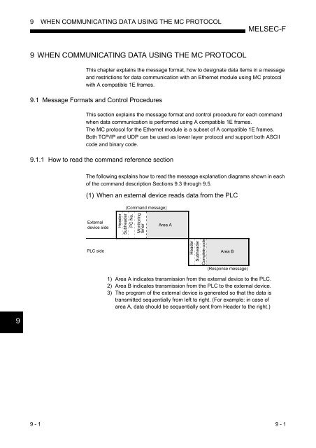
- Page 157 and 158: 9WHEN COMMUNICATING DATA USING THE
- Page 159 and 160: 9WHEN COMMUNICATING DATA USING THE
- Page 161 and 162: 9WHEN COMMUNICATING DATA USING THE
- Page 163 and 164: 9WHEN COMMUNICATING DATA USING THE
- Page 165 and 166: 9WHEN COMMUNICATING DATA USING THE
- Page 167 and 168: 9WHEN COMMUNICATING DATA USING THE
- Page 169 and 170: 9WHEN COMMUNICATING DATA USING THE
- Page 171 and 172: 9WHEN COMMUNICATING DATA USING THE
- Page 173 and 174: 9WHEN COMMUNICATING DATA USING THE
- Page 175 and 176: 9WHEN COMMUNICATING DATA USING THE
- Page 177 and 178: 9WHEN COMMUNICATING DATA USING THE
- Page 179 and 180: 9WHEN COMMUNICATING DATA USING THE
- Page 181 and 182: 9WHEN COMMUNICATING DATA USING THE
- Page 183 and 184: 9WHEN COMMUNICATING DATA USING THE
- Page 185 and 186: 9WHEN COMMUNICATING DATA USING THE
- Page 187 and 188: 9WHEN COMMUNICATING DATA USING THE
- Page 189 and 190: 9WHEN COMMUNICATING DATA USING THE
- Page 191 and 192: 9WHEN COMMUNICATING DATA USING THE
- Page 193 and 194: 9WHEN COMMUNICATING DATA USING THE
- Page 195 and 196: 10USING THE E-MAIL FUNCTIONMELSEC-F
- Page 197 and 198: 10USING THE E-MAIL FUNCTIONMELSEC-F
- Page 199 and 200: 10USING THE E-MAIL FUNCTIONMELSEC-F
- Page 201 and 202: 10USING THE E-MAIL FUNCTIONMELSEC-F
- Page 203 and 204: 10USING THE E-MAIL FUNCTIONMELSEC-F
- Page 205 and 206:
10USING THE E-MAIL FUNCTIONMELSEC-F
- Page 207 and 208:
10USING THE E-MAIL FUNCTIONMELSEC-F
- Page 209 and 210:
10USING THE E-MAIL FUNCTIONMELSEC-F
- Page 211 and 212:
10USING THE E-MAIL FUNCTIONMELSEC-F
- Page 213 and 214:
11TROUBLESHOOTINGMELSEC-F11 TROUBLE
- Page 215 and 216:
11TROUBLESHOOTINGMELSEC-F6 SD7 RDLE
- Page 217 and 218:
11TROUBLESHOOTINGMELSEC-F(4) How to
- Page 219 and 220:
11TROUBLESHOOTINGMELSEC-F11.2.1 Buf
- Page 221 and 222:
11TROUBLESHOOTINGMELSEC-F11.2.2 Eth
- Page 223 and 224:
11TROUBLESHOOTINGMELSEC-F11.4 Error
- Page 225 and 226:
11TROUBLESHOOTINGMELSEC-F(5) Error
- Page 227 and 228:
11TROUBLESHOOTINGMELSEC-F(6) E-mail
- Page 229 and 230:
11TROUBLESHOOTINGMELSEC-F11.4.2 End
- Page 231 and 232:
11TROUBLESHOOTINGMELSEC-F11.4.4 Err
- Page 233 and 234:
11TROUBLESHOOTINGMELSEC-FStorage de
- Page 235 and 236:
11TROUBLESHOOTINGMELSEC-FStorage de
- Page 237 and 238:
11TROUBLESHOOTINGMELSEC-FStorage de
- Page 239 and 240:
11TROUBLESHOOTINGMELSEC-FStorage de
- Page 241 and 242:
11TROUBLESHOOTINGMELSEC-FStorage de
- Page 243 and 244:
11TROUBLESHOOTINGMELSEC-F(2) When c
- Page 245 and 246:
11TROUBLESHOOTINGMELSEC-F1)Is initi
- Page 247 and 248:
11TROUBLESHOOTINGMELSEC-F11.5.1 Sen
- Page 249 and 250:
11TROUBLESHOOTINGMELSEC-F11.5.2 Rec
- Page 251 and 252:
11TROUBLESHOOTINGMELSEC-FPOINTIf th
- Page 253 and 254:
11TROUBLESHOOTINGMELSEC-F1)Is the I
- Page 255 and 256:
APPENDIXMELSEC-FAPPENDIXAppendix 1
- Page 257 and 258:
APPENDIXMELSEC-F[Calculation exampl
- Page 259 and 260:
APPENDIXMELSEC-FAppendix 4 Program
- Page 261 and 262:
APPENDIXMELSEC-F(3) FX Configurator
- Page 263 and 264:
APPENDIXMELSEC-F/ *****************
- Page 265 and 266:
APPENDIXMELSEC-FCloseflag=FLAG_ON;/
- Page 267 and 268:
APPENDIXMELSEC-F}case ERROR_BIND:pr
- Page 269 and 270:
APPENDIXMELSEC-F(4) Window example
- Page 271 and 272:
APPENDIXMELSEC-FDim RxResponse As S
- Page 273 and 274:
APPENDIXMELSEC-FAppendix 5 Differen
- Page 275 and 276:
APPENDIXMELSEC-FRecording sheet 2[B
- Page 277 and 278:
APPENDIXMELSEC-FRecording sheet 4[B
- Page 279 and 280:
APPENDIXMELSEC-FAppendix 8 Versioin
- Page 281 and 282:
WarrantyPlease confirm the followin
- Page 284:
FX3U-ENET-LUSER’S MANUALHEAD OFFI


