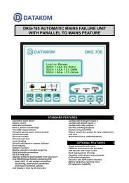
DKG-705 AUTOMATIC MAINS FAILURE AND REMOTE START ...
DKG-705 AUTOMATIC MAINS FAILURE AND REMOTE START ...
DKG-705 AUTOMATIC MAINS FAILURE AND REMOTE START ...
Create successful ePaper yourself
Turn your PDF publications into a flip-book with our unique Google optimized e-Paper software.
DATAKOM<strong>DKG</strong>-<strong>705</strong> User’s ManualTerm Function Technical data Description30 GROUND O VDC Power supply negative connection.31 CHARGE Input and output Connect the charge alternator’s D+ terminalto this terminal. This terminal will supply theexcitation current and measure the voltage ofthe charge alternator.32 RELAY-6 (FUEL RELAY) Output 10A/28VDC This relay is normally used for fuel solenoidcontrol. It is internally connected to terminal 31for supplying the charge alternator’s excitationcurrent.33 RELAY-2 (CRANK RELAY) Output 10A/28VDC This relay has programmable function,selectable from a list. However it is generallyused as engine crank output.34 BATTERY POSITIVE +12 or 24VDC The positive terminal of the DC Supply shallbe connected to this terminal. The unitoperates on both 12V and 24V batterysystems, depending on the voltage selectionjumper. Do not operate a 12V-DC unit with a24V-DC system. This may cause thedestruction of the unit. Always disconnectthe voltage selector jumper of a stocked unit.35 RELAY-7 (STOP RELAY) Output 10A/28VDC36 RELAY-1 (PREHEAT) Output 10A/28VDC37 RELAY-3 (ALARM RELAY) Output 10A/28VDCThese relays have programmable functions,selectable from a list.Term Function Technical data Description38 CURR_R+Current transformer Connect the mains current transformer39 CURR_R-inputs, 5A-AC terminals to these inputs. Do not connect the40 CURR_S+same current transformer to other units than41 CURR_S-<strong>DKG</strong>-<strong>705</strong> otherwise a unit fault will occur.42 CURR_T+Connect each terminal of the transformer to43 CURR_T-the unit’s related terminal. Do not usecommon terminals. Do not use grounding.Correct polarity of connection is vital. If themeasured power is negative, then change thepolarity of each 3 current transformers. Therating of the transformers should be the samefor each of the 3 phases. The secondarywinding rating shall be 5 Amperes. (For ex.200/5 Amps).Term Function Technical data Description44 MAGNETIC PICKUP Inputs, 0.5-70V Connect the magnetic pickup signal to these45 MAGNETIC PICKUP 0-20KHzinputs.46 AVR CONTROLOutput,AVR voltage control outputs. Connect to the47 AVR CONTROLisolated resistor,300-1500 ohms.external adjust potentiometer terminals of theAVR. The polarity is not important.48 GOVERNOR CONTROL Output, 0-10VDC Connect this output to the terminal ‘J’ of thespeed governor.<strong>705</strong>-UE.doc - 8 -


