C10- PARALLEL PORT INTERFACE CARD Rev. 10 - CNC4PC
C10- PARALLEL PORT INTERFACE CARD Rev. 10 - CNC4PC
C10- PARALLEL PORT INTERFACE CARD Rev. 10 - CNC4PC
- No tags were found...

Create successful ePaper yourself
Turn your PDF publications into a flip-book with our unique Google optimized e-Paper software.
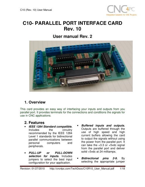
<strong>C<strong>10</strong></strong> (<strong>Rev</strong>. <strong>10</strong>) User Manual3. Specifications.DIGITAL INPUT SPECIFICATIONSOn-state voltage range2 to 5V DCMaximum off-state voltaje 0.8VMaximum operation frequency4 MHzTypical signal delay<strong>10</strong>nSDIGITAL OUTPUT SPECIFICATIONSMaximum output voltage (5V power supply voltage) + 0.5VTypical output current24mAMaximum off-state voltaje0.44 VMaximum operation frequency4 MHzTypical signal delay<strong>10</strong> nSTime of transition to high impedance state12 nS**Time passed since a low in the ENABLE input is detected and the outputs are disabled.<strong>Rev</strong>ision: 01/27/20<strong>10</strong> http://cnc4pc.com/TechDocs/<strong>C<strong>10</strong></strong>R<strong>10</strong>_User_Manual.pdf 3/18
<strong>C<strong>10</strong></strong> (<strong>Rev</strong>. <strong>10</strong>) User Manual4. Board description4.1 Using configuration jumper.4.1.1 Using the COM configuration jumper.There is a jumper (X7) that allows youto select +5VDC or GND for the COMpins.1-2: COM= GND2-3: COM= +5VDC<strong>Rev</strong>ision: 01/27/20<strong>10</strong> http://cnc4pc.com/TechDocs/<strong>C<strong>10</strong></strong>R<strong>10</strong>_User_Manual.pdf 4/18
<strong>C<strong>10</strong></strong> (<strong>Rev</strong>. <strong>10</strong>) User Manual4.1.2 Using the Pins 2-9 direction jumper.There is a jumper (X6) to selectthe pins 2-9 direction.1-2: OUTPUTS2-3: INPUTS4.1.3 Using the Pull-up or Pull-down selection jumper for pins 2-9.Jumper (X4) allows change the inputconfiguration for pins 2-9. Using the Pullupor Pull-down selection jumpers for pins2-9 the input voltage is pulled through a4.7Kohm resistor to up or down in thisway:1-2: PULL-DOWN2-3: PULL-UP<strong>Rev</strong>ision: 01/27/20<strong>10</strong> http://cnc4pc.com/TechDocs/<strong>C<strong>10</strong></strong>R<strong>10</strong>_User_Manual.pdf 5/18
<strong>C<strong>10</strong></strong> (<strong>Rev</strong>. <strong>10</strong>) User Manual4.1.4 Using the Pull-up or Pull-down selection jumper for pins <strong>10</strong>,11, 12, 13 and 15.Jumper (X5) allows change the inputconfiguration for pins <strong>10</strong>, 11, 12, 13 and 15.Using the Pull-up or Pull-down selectionjumpers for those pins will pull them up ordown through a 4.7Kohm resistor:1-2: PULL-DOWN2-3: PULL-UP4.1.5 Enable pin.The card must be provided with a 5VDC signal to enable operation. This featurehas been added to externally control the status of the outputs. An external switchor a Safety Charge Pump can be added to provide the enabling signal. When theenable signal is not present, output signals sent high impedance state. If thisfunction is not required, an jumper can be placed between +5vdc and the ENterminal. It has an internal 4.7kOhm pull-down resistor.Wiring:The Parallel Port InterfaceCard has a very basicdesign that provides theflexibility you look for onCNC projects.WARNING: This card must have the power supplied while it is connected tothe PC. If power is removed to the card while it is connected to the PC, noise canbe introduced to the output lines. This can create a dangerous situation as relaysor other devices that might be connected to this card could get activated.<strong>Rev</strong>ision: 01/27/20<strong>10</strong> http://cnc4pc.com/TechDocs/<strong>C<strong>10</strong></strong>R<strong>10</strong>_User_Manual.pdf 6/18
<strong>C<strong>10</strong></strong> (<strong>Rev</strong>. <strong>10</strong>) User Manual5. Connection instructionsRequirements:It requires a 5VDC @ 400 milliamps power supply to operate. This power can betaken from the computer’s power supply or USB port. Consider using the A3 – USBPower Cable found under Accessories in the website.WARNINGCheck the polarity and voltage of the external power source and connect the 5Vand GND (X1). Overvoltage or reverse-polarity power applied to these terminalscan cause damage to the board, and/or the power source. Follow the stepsbellow.Step 1. Set the configuration jumpers (X4, X5, X6 y X7) as are required by yoursystem. Note: Is important to understand the selection jumper functions (see section 4.1)and to know the input and output features of the devices to be connected to this board toreach a good couple.Step 2. Ensure that all external power sources are set to OFF.Step 3. Connect the power supply to the Power Inputs Connectors (X1).Step 4. Connect the parallel cable coming from the PC to the Female DB25Connector (X3). Note: If this board is not connected to the PC, the outputs will bedeactivated.Step 5. Connect to the board the components of the system.Step 6. Turn on the external supplies and check that the power led indicator (X2)lights.Step 7. Apply 5V to the enable pin (X8) to activate the outputs.<strong>Rev</strong>ision: 01/27/20<strong>10</strong> http://cnc4pc.com/TechDocs/<strong>C<strong>10</strong></strong>R<strong>10</strong>_User_Manual.pdf 7/18
<strong>C<strong>10</strong></strong> (<strong>Rev</strong>. <strong>10</strong>) User Manual6. Functional Block Diagrams6.1 Bidirectional pins simplified block diagramFig. 1 Simplified functional block diagram for the 2-9 pins.A Pull-up or Pull-down selection jumper allows selecting the configuration for the allbidirectional pins (2-9) when they are set as inputs.6.2 Outputs simplified block diagramFig. 2 Simplified functional block diagram for the outputs.<strong>Rev</strong>ision: 01/27/20<strong>10</strong> http://cnc4pc.com/TechDocs/<strong>C<strong>10</strong></strong>R<strong>10</strong>_User_Manual.pdf 8/18
<strong>C<strong>10</strong></strong> (<strong>Rev</strong>. <strong>10</strong>) User Manual6.3 Dedicated Inputs simplified block diagramFig. 3 Simplified functional block diagram for the inputs.A Pull-up or Pull-down selection jumper allows selecting the configuration for the alldedicated inputs (pins <strong>10</strong>, 11, 12, 13 and 15).<strong>Rev</strong>ision: 01/27/20<strong>10</strong> http://cnc4pc.com/TechDocs/<strong>C<strong>10</strong></strong>R<strong>10</strong>_User_Manual.pdf 9/18
<strong>C<strong>10</strong></strong> (<strong>Rev</strong>. <strong>10</strong>) User Manual7. Wiring diagramsWhile this board supports only TTL +5VDC signals, different kind of sensors,switches using different voltages can be connected using the diagrams that follow:Note. This board has two possible inputs banks, (bidirectional pins: 2-9) and (dedicated inputs: pins<strong>10</strong>, 11, 12, 13 and 15), and all the inputs of the same bank have the same configuration. The belowwiring diagrams are an example, any input can be used for the connections.Note. The bellow wiring diagrams require setting the inputs to use pull-downresistor.7.1 Connecting Switches or push button.Fig. 3 Wiring diagram to connect switches.7.2 Connecting NPN sensors.<strong>Rev</strong>ision: 01/27/20<strong>10</strong> http://cnc4pc.com/TechDocs/<strong>C<strong>10</strong></strong>R<strong>10</strong>_User_Manual.pdf <strong>10</strong>/18
<strong>C<strong>10</strong></strong> (<strong>Rev</strong>. <strong>10</strong>) User ManualFig. 4 Wiring diagram to connect NPN open collector proximity sensors.Fig. 5 Wiring diagram to connect in parallel NPN open collector proximity sensors.Connecting NPN open collector proximity sensor with the <strong>C<strong>10</strong></strong>R1 Value (12V)R1 Value (24V)Aprox. <strong>10</strong>KΩAprox. 25KΩ<strong>Rev</strong>ision: 01/27/20<strong>10</strong> http://cnc4pc.com/TechDocs/<strong>C<strong>10</strong></strong>R<strong>10</strong>_User_Manual.pdf 11/18
<strong>C<strong>10</strong></strong> (<strong>Rev</strong>. <strong>10</strong>) User ManualFig. 6 Wiring diagram to connect NPN proximity sensors with internal pull up resistor.Some NPN proximity sensor has a pull-up resistor (R1) internally. It is necessaryto know its value in order to connect safely the sensor with the BOB. Follow thisrecommendation:Connecting NPN open collector proximity sensor with the <strong>C<strong>10</strong></strong>(R1+R2) Value (12V)Aprox. <strong>10</strong>KΩ(R1+R2) Value (24V)Aprox. 25KΩ<strong>Rev</strong>ision: 01/27/20<strong>10</strong> http://cnc4pc.com/TechDocs/<strong>C<strong>10</strong></strong>R<strong>10</strong>_User_Manual.pdf 12/18
<strong>C<strong>10</strong></strong> (<strong>Rev</strong>. <strong>10</strong>) User ManualCalculating the R1 value.Note: Rx is the unknown resistor value.R X = V EX .(R/V) - R (1)Where:V EX is the external power supply voltageV is the voltage across the R resistorAn external resistor and a voltmeter are required to calculate the internal resistor (Rx)value.Note. The user should know the R value to do this operation. A 4.7KOhm @ 1/2W isrecommended.SAMPLE: if you are using a 12V power supply (V EX ), and using a 4.7KOhm asexternal resistor (R), then the voltage across R should be 6V, using the equation 1,the Rx value is 4.7KOhm.<strong>Rev</strong>ision: 01/27/20<strong>10</strong> http://cnc4pc.com/TechDocs/<strong>C<strong>10</strong></strong>R<strong>10</strong>_User_Manual.pdf 13/18
<strong>C<strong>10</strong></strong> (<strong>Rev</strong>. <strong>10</strong>) User Manual7.3 Connecting PNP sensors.Fig. 7 Wiring diagram to connect PNP proximity sensorsConnecting PNP proximity sensor with the <strong>C<strong>10</strong></strong>R Value (12V)R Value (24V)Aprox. <strong>10</strong>KΩAprox. 25KΩ<strong>Rev</strong>ision: 01/27/20<strong>10</strong> http://cnc4pc.com/TechDocs/<strong>C<strong>10</strong></strong>R<strong>10</strong>_User_Manual.pdf 14/18
<strong>C<strong>10</strong></strong> (<strong>Rev</strong>. <strong>10</strong>) User Manual7.4 Other connections.Other connections can be implemented by setting the inputs to pull-upresistor.This example shows how to do an Auto Tool Zero by setting the inputs with pull-upresistor.Fig. 8 Wiring diagram to do an “Auto Tool Zero”Other wiring diagrams samples are shown in the next links.http://cnc4pc.com/Tech_Docs/E_STOP_N_EN_Wiring.pdfhttp://cnc4pc.com/Tech_Docs/E_STOP_N_SCHP.pdfhttp://cnc4pc.com/Tech_Docs/<strong>C<strong>10</strong></strong>R8_WD2.pdf<strong>Rev</strong>ision: 01/27/20<strong>10</strong> http://cnc4pc.com/TechDocs/<strong>C<strong>10</strong></strong>R<strong>10</strong>_User_Manual.pdf 15/18
<strong>C<strong>10</strong></strong> (<strong>Rev</strong>. <strong>10</strong>) User Manual7. Troubleshooting.SYMPTOM 1: THE BOARD DOES NOT RELAY THE SIGNALS.POSSIBLE CAUSEPOSSIBLE SOLUTIONS- Pin conflict or mach3 configuration.It is possible that the port addressused for the pin is not right, or thatthere is a pin conflict with the. That isthat you are using that same pin twice.(it could be assigned to a differentfunction).- The board does not like thewaveform it is getting. Somebreakout boards could invert thesignals or modify the pulse width.Changing the active low status of thepin used also inverts the waveform.- The signal or frequencies are notgetting to the board. It could be thecable or that you are passing thesignal through the same breakoutboard that you are enabling/disabling,so the outputs could be disabled, sothey will not get to the breakout board.- Problems with Mach3 PulseGeneration. Mach3 could haveinstallation problems (you did notrestart immediately after installation),or there could be something creating aconflict. Some dongle devices mightcause this, other software, likeQuickTime or drivers for touch screen.- Go to the device manager in windows,and check the memory address used forthe parallel port you are using. Usually itwill be 378 for LPT1. Check also thatthe port does not have a conflict. Thenin mach3, go to Ports & Pins / Port Setupand Axis Selection. Check the memoryaddress is correct.- Check that the pin you are using is notbeen used anywhere else in your setup.Got to motor output and output signals,and check all the entries.- Play with the active low status of the pinused for the frequency.- Try a different cable.- Test the pins in the cable (before theyreach the breakout board) with amultimeter.- Test this in a different PC.- Follow Art’s suggestions for optimizingup WinXP:http://www.machsupport.com/downloads/XP_Optimization.txt.<strong>Rev</strong>ision: 01/27/20<strong>10</strong> http://cnc4pc.com/TechDocs/<strong>C<strong>10</strong></strong>R<strong>10</strong>_User_Manual.pdf 16/18
<strong>C<strong>10</strong></strong> (<strong>Rev</strong>. <strong>10</strong>) User ManualSYMPTOM 2: THE OUTPUTS DO NOT GET ENABLED / NO SIGNALS ARECOMING OUT.POSSIBLE CAUSEPOSSIBLE SOLUTIONS- The EN terminal (Enable Outputs) isnot enabled. The board requires to beexternally enabled.- The parallel cable is not wellconnected to the PC parallel port.- Make sure you are providing +5vdc tothe EN terminal. This +5vdc can betaken from the terminal next to it.- Check if the parallel port is wellconnected to the PC.SYMPTOM 3: THERE IS NOISE IN THE SYSTEM, OR THE MOTORS DO NOTMOVE SMOOTHLY.POSSIBLE CAUSEPOSSIBLE SOLUTIONS- The board could be underpowered. - Make sure you are using a +5vdc400mA power supply.- There could be a short that could bedraining the power to the board.- There could be an external noisesource that could be introducingnoise into the system.- Check that there are no hot spots in theboard or it’s connections.- Measure the board’s powerconsumption, it should be less than400mA (depending on the featuresused).- Blown chips could create an internalshort and end up drawing power that canaffect how other chips work.- Try using shielded cables.- Try to isolate VFDs or AC servos, etc.- Try using <strong>10</strong>3. 0.1mF caps between theI/O terminal and a ground of the board.SYMPTOM 5: A I/O PIN MIGHT NOT BE WORKING.POSSIBLE CAUSEPOSSIBLE SOLUTIONS- A chip may have gone bad. Thesebuffers could act as fuses for thesignals, and they can go bad becauseof noise spikes or even strong static.- These chips are inexpensive and readilyavailable. You can order them here:http://www.cnc4pc.com/Store/osc/index.php?cPath=38_43.- Carefully moving chips around andchecking if the problem moves around<strong>Rev</strong>ision: 01/27/20<strong>10</strong> http://cnc4pc.com/TechDocs/<strong>C<strong>10</strong></strong>R<strong>10</strong>_User_Manual.pdf 17/18
<strong>C<strong>10</strong></strong> (<strong>Rev</strong>. <strong>10</strong>) User Manualcould be a way of figuring out if this isthe case.- There could be a problem with theparallel cable or parallel port.- Test this with a different PC or parallelport.8. Dimensions.All dimensions are in Millimeters.Disclaimer:Use caution. CNC machines could be dangerous machines. DUNCAN USA, LLCor Arturo Duncan are not liable for any accidents resulting from the improper use ofthese devices. The <strong>C<strong>10</strong></strong> is not fail-safe device, and it should not be used in lifesupport systems or in other devices where its failure or possible erratic operationcould cause property damage, bodily injury or loss of life.<strong>Rev</strong>ision: 01/27/20<strong>10</strong> http://cnc4pc.com/TechDocs/<strong>C<strong>10</strong></strong>R<strong>10</strong>_User_Manual.pdf 18/18