C50- PARALLEL PORT INTERFACE CARD Rev. 1 User ... - CNC4PC
C50- PARALLEL PORT INTERFACE CARD Rev. 1 User ... - CNC4PC
C50- PARALLEL PORT INTERFACE CARD Rev. 1 User ... - CNC4PC
- No tags were found...

Create successful ePaper yourself
Turn your PDF publications into a flip-book with our unique Google optimized e-Paper software.
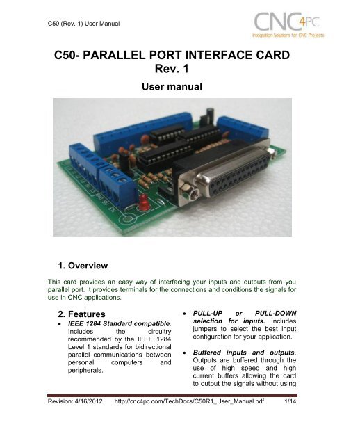
<strong>C50</strong> (<strong>Rev</strong>. 1) <strong>User</strong> Manual<strong>C50</strong>- <strong>PARALLEL</strong> <strong>PORT</strong> <strong>INTERFACE</strong> <strong>CARD</strong><strong>Rev</strong>. 1<strong>User</strong> manual1. OverviewThis card provides an easy way of interfacing your inputs and outputs from youparallel port. It provides terminals for the connections and conditions the signals foruse in CNC applications.2. FeaturesIEEE 1284 Standard compatible.Includes the circuitryrecommended by the IEEE 1284Level 1 standards for bidirectionalparallel communications betweenpersonal computers andperipherals. PULL-UP or PULL-DOWNselection for inputs. Includesjumpers to select the best inputconfiguration for your application.Buffered inputs and outputs.Outputs are buffered through theuse of high speed and highcurrent buffers allowing the cardto output the signals without using<strong>Rev</strong>ision: 4/16/2012 http://cnc4pc.com/TechDocs/<strong>C50</strong>R1_<strong>User</strong>_Manual.pdf 1/14
<strong>C50</strong> (<strong>Rev</strong>. 1) <strong>User</strong> Manualthe power from the parallel port. Itcan take the +3.3 or +5vdc signalfrom the parallel port and deliversolid +5vdc at 24 milliamps. Output pins 1, 2, 3, 4, 5, 6, 7, 8,9, 14, 16, 17. Input pins 10, 11, 12, 13, 15. The common terminal to pins 2-9 can be ground or +5vdc.Forget about grounding problems.Easily connect your pin by usingyour close by ground connection.No need to be an electronicsexpert to ground all your stuff. Theboard has a jumper that allowsyou to select if the commonterminal to pins 2-9 will carry aground or +5vdc. So if you areconnecting encoders or proximityswitches, you can select it toground. If you are connectingGeckodrives or limit switches, youcan set It to be +5VDC.other external safety monitoringdevice.Works directly with popularCNC hardware and software.Such as Geckodrive, DeskCNC orRutex, and parallel port controlsoftware, such as mach2, LinuxEMC, TurboCNC, CNCPlayer,CNCZeus and others. (Not alltested).All TTL 5VDC signals. Interfacedirectly with parallel port interfaceproducts and other <strong>CNC4PC</strong>cards. 5VDC (TTL) cards are verycommon among automationdevices.Screw-On connections for allterminals. You only have toscrew-on the wires to make allyour connections.External Enable Pin (EN). Theboard has a pin that allows you toenable/disable all the outputs andinputs 11, 12, 13 and 15 at once.Only input 10 will be alwaysenabled. The board requires+5vdc in the EN pin. If it is notpresent, it will send all the outputsto high impedance and the inputsto an high. You can use this toenable or disable the systemmanually, or you can install anexternal Safety Charge Pump or<strong>Rev</strong>ision: 4/16/2012 http://cnc4pc.com/TechDocs/<strong>C50</strong>R1_<strong>User</strong>_Manual.pdf 2/14
<strong>C50</strong> (<strong>Rev</strong>. 1) <strong>User</strong> Manual3. Specifications.DIGITAL INPUT SPECIFICATIONSOn-state voltage range2 to 5V DCMaximum off-state voltaje 0.8VMaximum operation frequency4 MHzTypical signal delay10nSDIGITAL OUTPUT SPECIFICATIONSMaximum output voltage (5V power supply voltage) + 0.5VTypical output current24mAMaximum off-state voltaje0.44 VMaximum operation frequency4 MHzTypical signal delay10 nSTime of transition to high impedance state12 nS**Time passed since a low in the ENABLE input is detected and the outputs are disabled.4. Board description<strong>Rev</strong>ision: 4/16/2012 http://cnc4pc.com/TechDocs/<strong>C50</strong>R1_<strong>User</strong>_Manual.pdf 3/14
<strong>C50</strong> (<strong>Rev</strong>. 1) <strong>User</strong> Manual4.1 Using configuration jumper.4.1.1 Using the COM configuration jumper.There is a jumper that allows you toselect +5VDC or GND for the COMpins.1-2: COM= GND2-3: COM= +5VDC4.1.2 Using the Pull-up or Pull-down selection jumper for pins 10,11, 12, 13 and 15.That jumper allows change the inputconfiguration for pins 10, 11, 12, 13 and 15.Using the Pull-up or Pull-down selectionjumpers for those pins will pull them up ordown through a 4.7Kohm resistor:1-2: PULL-DOWN2-3: PULL-UP4.1.3 Enable pin.The card must be provided with a 5VDC signal to enable operation. This featurehas been added to externally control the status of the outputs and inputs 11, 12, 13and 15. NOTE: Only Pin 10 will be not affected by the status of the Enable pin.An external switch or a Safety Charge Pump can be added to provide the enablingsignal. When the enable signal is not present, output and inputs signals sent highimpedance state. If this function is not required, an jumper can be placed between+5vdc and the EN terminal. It has an internal 4.7kOhm pull-down resistor.<strong>Rev</strong>ision: 4/16/2012 http://cnc4pc.com/TechDocs/<strong>C50</strong>R1_<strong>User</strong>_Manual.pdf 4/14
<strong>C50</strong> (<strong>Rev</strong>. 1) <strong>User</strong> ManualWiring:The Parallel Port InterfaceCard has a very basicdesign that provides theflexibility you look for onCNC projects.WARNING: This card must have the power supplied while it is connected tothe PC. If power is removed to the card while it is connected to the PC, noise canbe introduced to the output lines. This can create a dangerous situation as relaysor other devices that might be connected to this card could get activated.5. Connection instructionsRequirements:It requires a 5VDC @ 250 milliamps power supply to operate. This power can betaken from the computer’s power supply or USB port. Consider using the A3 – USBPower Cable found under Accessories in this website.WARNINGCheck the polarity and voltage of the external power source and connect the 5Vand GND. Overvoltage or reverse-polarity power applied to these terminals cancause damage to the board, and/or the power source. Follow the steps bellow.Step 1. Set the configuration jumpers as are required by your system. Note: Isimportant to understand the selection jumper functions (see section 4.1) and to know theinput and output features of the devices to be connected to this board to reach a goodcouple.Step 2. Ensure that all external power sources are set to OFF.Step 3. Connect the power supply to the Power Terminals.<strong>Rev</strong>ision: 4/16/2012 http://cnc4pc.com/TechDocs/<strong>C50</strong>R1_<strong>User</strong>_Manual.pdf 5/14
<strong>C50</strong> (<strong>Rev</strong>. 1) <strong>User</strong> ManualStep 4. Connect the parallel cable coming from the PC to the Female DB25Connector. Note: If this board is not connected to the PC, the outputs and inputs 11, 12, 13,and 15 will be deactivated.Step 5. Connect to the board the components of the system.Step 6. Turn on the external supplies and check that the power led indicator lights.Step 7. Apply 5V to the enable pin to activate the outputs and inputs 11, 12, 13and 15.6. Functional Block Diagrams6.1 Outputs 2-9 simplified block diagramSimplified functional block diagram for the 2-9 pins.<strong>Rev</strong>ision: 4/16/2012 http://cnc4pc.com/TechDocs/<strong>C50</strong>R1_<strong>User</strong>_Manual.pdf 6/14
<strong>C50</strong> (<strong>Rev</strong>. 1) <strong>User</strong> Manual6.2 Outputs 1, 14, 16 and 17 simplified block diagramSimplified functional block diagram for the outputs.6.3 Dedicated Inputs simplified block diagramFig. 3 Simplified functional block diagram for the inputs.A Pull-up or Pull-down selection jumper allows selecting the configuration for the alldedicated inputs (pins 10, 11, 12, 13 and 15).<strong>Rev</strong>ision: 4/16/2012 http://cnc4pc.com/TechDocs/<strong>C50</strong>R1_<strong>User</strong>_Manual.pdf 7/14
<strong>C50</strong> (<strong>Rev</strong>. 1) <strong>User</strong> Manual7. Wiring diagramsWhile this board supports only TTL +5VDC signals, different kind of sensors,switches using different voltages can be connected using the diagrams that follow:Note. The below wiring diagrams are an example, any input can be used for the connections.Note. The bellow wiring diagrams require setting the inputs to use pull-downresistor.7.1 Connecting Switches or push button.Wiring diagram to connect switches.<strong>Rev</strong>ision: 4/16/2012 http://cnc4pc.com/TechDocs/<strong>C50</strong>R1_<strong>User</strong>_Manual.pdf 8/14
<strong>C50</strong> (<strong>Rev</strong>. 1) <strong>User</strong> Manual7.2 Connecting NPN sensors.Wiring diagram to connect NPN open collector proximity sensors.<strong>Rev</strong>ision: 4/16/2012 http://cnc4pc.com/TechDocs/<strong>C50</strong>R1_<strong>User</strong>_Manual.pdf 9/14
<strong>C50</strong> (<strong>Rev</strong>. 1) <strong>User</strong> ManualWiring diagram to connect in parallel NPN open collector proximity sensors.Connecting NPN open collector proximity sensor with the <strong>C50</strong>R1 Value (12V)R1 Value (24V)Aprox. 10KΩAprox. 25KΩWiring diagram to connect NPN proximity sensors with internal pull up resistor.Some NPN proximity sensor has a pull-up resistor (R1) internally. It is necessaryto know its value in order to connect safely the sensor with the BOB. Follow thisrecommendation:Connecting NPN open collector proximity sensor with the <strong>C50</strong>(R1+R2) Value (12V)Aprox. 10KΩ(R1+R2) Value (24V)Aprox. 25KΩ<strong>Rev</strong>ision: 4/16/2012 http://cnc4pc.com/TechDocs/<strong>C50</strong>R1_<strong>User</strong>_Manual.pdf 10/14
<strong>C50</strong> (<strong>Rev</strong>. 1) <strong>User</strong> ManualCalculating the R1 value.Note: Rx is the unknown resistor value.R X = V EX .(R/V) - R (1)Where:V EX is the external power supply voltageV is the voltage across the R resistorAn external resistor and a voltmeter are required to calculate the internal resistor (Rx)value.Note. The user should know the R value to do this operation. A 4.7KOhm @ 1/2W isrecommended.SAMPLE: if you are using a 12V power supply (V EX ), and using a 4.7KOhm asexternal resistor (R), then the voltage across R should be 6V, using the equation 1,the Rx value is 4.7KOhm.<strong>Rev</strong>ision: 4/16/2012 http://cnc4pc.com/TechDocs/<strong>C50</strong>R1_<strong>User</strong>_Manual.pdf 11/14
<strong>C50</strong> (<strong>Rev</strong>. 1) <strong>User</strong> Manual7.3 Connecting PNP sensors.Wiring diagram to connect PNP proximity sensorsConnecting PNP proximity sensor with the <strong>C50</strong>R Value (12V)R Value (24V)Aprox. 10KΩAprox. 25KΩ<strong>Rev</strong>ision: 4/16/2012 http://cnc4pc.com/TechDocs/<strong>C50</strong>R1_<strong>User</strong>_Manual.pdf 12/14
<strong>C50</strong> (<strong>Rev</strong>. 1) <strong>User</strong> Manual7.4 Other connections.Other connections can be implemented by setting the inputs to pull-upresistor.This example shows how to do an Auto Tool Zero by setting the inputs with pull-upresistor.Fig. 8 Wiring diagram to do an “Auto Tool Zero”<strong>Rev</strong>ision: 4/16/2012 http://cnc4pc.com/TechDocs/<strong>C50</strong>R1_<strong>User</strong>_Manual.pdf 13/14
<strong>C50</strong> (<strong>Rev</strong>. 1) <strong>User</strong> Manual7. Dimensions.All dimensions are in Millimeters.Disclaimer:Use caution. CNC machines could be dangerous machines. DUNCAN USA, LLCor Arturo Duncan are not liable for any accidents resulting from the improper use ofthese devices. This board is not fail-safe device, and it should not be used in lifesupport systems or in other devices where its failure or possible erratic operationcould cause property damage, bodily injury or loss of life.<strong>Rev</strong>ision: 4/16/2012 http://cnc4pc.com/TechDocs/<strong>C50</strong>R1_<strong>User</strong>_Manual.pdf 14/14