C50- PARALLEL PORT INTERFACE CARD Rev. 1 User ... - CNC4PC
C50- PARALLEL PORT INTERFACE CARD Rev. 1 User ... - CNC4PC
C50- PARALLEL PORT INTERFACE CARD Rev. 1 User ... - CNC4PC
- No tags were found...

You also want an ePaper? Increase the reach of your titles
YUMPU automatically turns print PDFs into web optimized ePapers that Google loves.
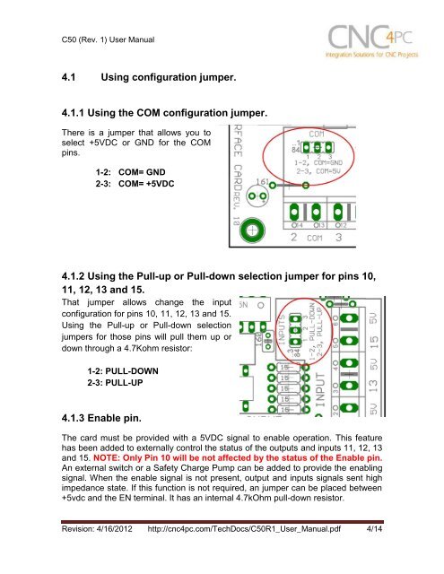
<strong>C50</strong> (<strong>Rev</strong>. 1) <strong>User</strong> Manual4.1 Using configuration jumper.4.1.1 Using the COM configuration jumper.There is a jumper that allows you toselect +5VDC or GND for the COMpins.1-2: COM= GND2-3: COM= +5VDC4.1.2 Using the Pull-up or Pull-down selection jumper for pins 10,11, 12, 13 and 15.That jumper allows change the inputconfiguration for pins 10, 11, 12, 13 and 15.Using the Pull-up or Pull-down selectionjumpers for those pins will pull them up ordown through a 4.7Kohm resistor:1-2: PULL-DOWN2-3: PULL-UP4.1.3 Enable pin.The card must be provided with a 5VDC signal to enable operation. This featurehas been added to externally control the status of the outputs and inputs 11, 12, 13and 15. NOTE: Only Pin 10 will be not affected by the status of the Enable pin.An external switch or a Safety Charge Pump can be added to provide the enablingsignal. When the enable signal is not present, output and inputs signals sent highimpedance state. If this function is not required, an jumper can be placed between+5vdc and the EN terminal. It has an internal 4.7kOhm pull-down resistor.<strong>Rev</strong>ision: 4/16/2012 http://cnc4pc.com/TechDocs/<strong>C50</strong>R1_<strong>User</strong>_Manual.pdf 4/14