C11- MULTIFUNCTION CNC BOARD Rev. 9.3 - Stepper Motor ...
C11- MULTIFUNCTION CNC BOARD Rev. 9.3 - Stepper Motor ...
C11- MULTIFUNCTION CNC BOARD Rev. 9.3 - Stepper Motor ...

You also want an ePaper? Increase the reach of your titles
YUMPU automatically turns print PDFs into web optimized ePapers that Google loves.
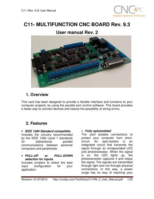
<strong>C11</strong> (<strong>Rev</strong>. <strong>9.3</strong>) User Manual<strong>C11</strong>- <strong>MULTIFUNCTION</strong> <strong>CNC</strong> <strong>BOARD</strong> <strong>Rev</strong>. <strong>9.3</strong>User manual <strong>Rev</strong>. 21. OverviewThis card has been designed to provide a flexible interface and functions to yourcomputer projects, by using the parallel port control software. This board providesa faster way to connect devices and reduce the possibility of wiring errors.2. Features• IEEE 1284 Standard compatible.Includes the circuitry recommendedby the IEEE 1284 Level 1 standardsfor bidirectional parallelcommunications between personalcomputers and peripherals• PULL-UP or PULL-DOWNselection for inputs.Includes jumpers to select the bestinput configuration for yourapplication.• Fully optosiolatedThe card isolates connections toprotect your computer from shortcircuit.An opto-isolator is anintegrated circuit that transmits thesignal through an encapsulated LEDand phototransistor. When the signalis on, the LED lights up, thephototransistor captures it and relaysthe signal. The signals are transmittedthrough light and not through physicalconnections. In this way, a powersurge has no way of reaching your<strong>Rev</strong>ision: 01/27/2010 http://cnc4pc.com/TechDocs/<strong>C11</strong>R9_3_User_Manual.pdf 1/22
<strong>C11</strong> (<strong>Rev</strong>. <strong>9.3</strong>) User Manualboard can be adjusted to othervoltages.• Two Built-in ElectromechanicalRelays with NO and NCpositions.• All pins can be used in aconcurrent manner.You can use all the input or outputpins in a concurrent manner. Forexample, if you are using output pin#1 to control the Built-inElectromechanical Relay, you canalso access that signal from theoutput pin on the board or from theDB25 connector for output. Eachconnection will not affect the othercurrent from the other connection.• Has an extra DB25 femaleconnection for output.You can use this card to optoisolateany existing setup just by connectingthis card between your computer andyour current setup. That way, you canalso see and access all your signals.This makes this card ideal for usewith the Xylotex, Hobby<strong>CNC</strong> or othernon-optoisolated boards. You onlyhave to add this board to a DB25male connection to a male cable.• Input and output pins with closeby ground connections.Forget about grounding problems.Easily connect your pin by using yourclose by ground connection. No needto be an electronics expert to groundall your stuff. The terminals next topins 2-9 can be set to have +5VDC orGND according to your needs. Thereis a jumpers that allows you to select+5VDC or GND for the COM pins.• Works directly with popular <strong>CNC</strong>hardware and software.That goes for Geckdrive, Desk<strong>CNC</strong> orRutex and parallel port controlsoftware such as mach2, Linux EMC,Turbo<strong>CNC</strong>, <strong>CNC</strong>Zeus and other/ (Notall have been tested).• Screw-On connections for allterminals.You only have to screw-on the wiresto make all your connections.<strong>Rev</strong>ision: 01/27/2010 http://cnc4pc.com/TechDocs/<strong>C11</strong>R9_3_User_Manual.pdf 3/22
<strong>C11</strong> (<strong>Rev</strong>. <strong>9.3</strong>) User Manual3. Specifications.DIGITAL INPUT SPECIFICATIONSNumbers of inputs 5On-state voltage range2 to 5V DCMaximum off-state voltaje 0.8VTypical signal delay2.8uSDIGITAL OUTPUT SPECIFICATIONSNumber of outputs 12Maximum output voltage (5V power supply voltage) + 0.5VTypical output current24mAMaximum off-state voltaje0.44 VTypical signal delay3uSTime of transition to high impedance state120mS*Time passed since a fault in the SCHP signal is detected and the outputs are disabled.The recommended pulse width for the inputs and outputs is 2us.<strong>Rev</strong>ision: 01/27/2010 http://cnc4pc.com/TechDocs/<strong>C11</strong>R9_3_User_Manual.pdf 4/22
<strong>C11</strong> (<strong>Rev</strong>. <strong>9.3</strong>) User Manual4. Functional Block Diagrams4.1 Outputs 2-9 simplified functional block diagramFig. 1 Simplified functional block diagram for the outputs 2-9.Parallel Port coupling is done following IEEE 1284 standard recommendation.An RC Low Pass filter followed by a Schmitt Trigger gate is used to help reducethe effect of the noise from drivers or other devices. LEDs are driven by a differentbuffer to avoid residual currents affecting the signal.4.2 Outputs 1, 14, 16 and 17 simplified functional block diagramFig. 2 Simplified functional block diagram for the outputs 1, 14, 16 and 17.Note: “Internal Enable” = “External Enable Pin” AND (“SCHP” OR “Bypassed SCHP”)<strong>Rev</strong>ision: 01/27/2010 http://cnc4pc.com/TechDocs/<strong>C11</strong>R9_3_User_Manual.pdf 5/22
<strong>C11</strong> (<strong>Rev</strong>. <strong>9.3</strong>) User ManualThe “Internal Enable” is the result of an AND Operation between the “External EnablePin”and the SCHP operation mode selected by the user.Note: The output will be deactivated if the board is not connected to the PCparallel port.4.3 Input simplified functional block diagramFig. 3 Simplified functional block diagram for the inputs.Pins 10, 11, 12, 13 and 15 can be set to pull-down or pull-up by selecting thejumper in the appropriate position.The input pins can be set to be pulled up or down with a 4.7Kohm resistor.1-2: PULL-UP2-3: PULL- DOWN<strong>Rev</strong>ision: 01/27/2010 http://cnc4pc.com/TechDocs/<strong>C11</strong>R9_3_User_Manual.pdf 6/22
<strong>C11</strong> (<strong>Rev</strong>. <strong>9.3</strong>) User Manual4.4 External Enable Pin.The card must be provided with a 5VDC signal to enable operation. This featurehas been added to externally control the status of the outputs. An external switchor a Safety Charge Pump can be added to provide the enabling signal. When theenable signal is not present, output signals sent high impedance state. If thisfunction is not required, an jumper can be placed between +5vdc and the ENterminal. It has an internal 4.7kOhm pull-down resistor.WARNING: This card must have the power supplied while it is connected tothe PC. If power is removed to the card while it is connected to the PC, noise canbe introduced to the output lines. This can create a dangerous situation as relaysor other devices that might be connected to this card could get activated.<strong>Rev</strong>ision: 01/27/2010 http://cnc4pc.com/TechDocs/<strong>C11</strong>R9_3_User_Manual.pdf 7/22
<strong>C11</strong> (<strong>Rev</strong>. <strong>9.3</strong>) User Manual5. Wiring diagramsWhile this board supports only TTL +5VDC signals, different kind of sensors,switches using different voltages can be connected using the diagrams that follow:Note: The below wiring diagrams are an example, any input can be used for the connections.Note. The bellow wiring diagrams require setting the inputs to use pull-downresistor.5.1 Connecting Switches or push button.Fig. 7 Wiring diagram to connect switches.<strong>Rev</strong>ision: 01/27/2010 http://cnc4pc.com/TechDocs/<strong>C11</strong>R9_3_User_Manual.pdf 8/22
<strong>C11</strong> (<strong>Rev</strong>. <strong>9.3</strong>) User Manual5.2 Connecting NPN sensors.Fig. 8 Wiring diagram to connect NPN open collector proximity sensors.Fig. 9 Wiring diagram to connect in parallel NPN open collector proximity sensors.Connecting NPN open collector proximity sensor with the <strong>C11</strong>R1 Value (12V)R1 Value (24V)Aprox. 10KΩAprox. 25KΩ<strong>Rev</strong>ision: 01/27/2010 http://cnc4pc.com/TechDocs/<strong>C11</strong>R9_3_User_Manual.pdf 9/22
<strong>C11</strong> (<strong>Rev</strong>. <strong>9.3</strong>) User ManualFig. 10 Wiring diagram to connect NPN proximity sensors with internal pull up resistor.Some NPN proximity sensor has a pull-up resistor (R1) internally. It is necessaryto know its value in order to connect safely the sensor with the BOB. Follow thisrecommendation:Connecting NPN open collector proximity sensor with the <strong>C11</strong>(R1+R2) Value (12V)Aprox. 10KΩ(R1+R2) Value (24V)Aprox. 25KΩ<strong>Rev</strong>ision: 01/27/2010 http://cnc4pc.com/TechDocs/<strong>C11</strong>R9_3_User_Manual.pdf 10/22
<strong>C11</strong> (<strong>Rev</strong>. <strong>9.3</strong>) User ManualCalculating the R1 value.Note: Rx is the unknown resistor value.R X = V EX .(R/V) - R (1)Where:V EX is the external power supply voltageV is the voltage across the R resistorAn external resistor and a voltmeter are required to calculate the internal resistor (Rx)value.Note. The user should know the R value to do this operation. A 4.7KOhm @ 1/2W isrecommended.SAMPLE: if you are using a 12V power supply (V EX ), and using a 4.7KOhm asexternal resistor (R), then the voltage across R should be 6V, using the equation 1,the Rx value is 4.7KOhm.5.3 Connecting PNP sensors.<strong>Rev</strong>ision: 01/27/2010 http://cnc4pc.com/TechDocs/<strong>C11</strong>R9_3_User_Manual.pdf 11/22
<strong>C11</strong> (<strong>Rev</strong>. <strong>9.3</strong>) User ManualFig. 11 Wiring diagram to connect PNP proximity sensorsConnecting PNP proximity sensor with the <strong>C11</strong>GR Value (12V)R Value (24V)Aprox. 10KΩAprox. 25KΩ<strong>Rev</strong>ision: 01/27/2010 http://cnc4pc.com/TechDocs/<strong>C11</strong>R9_3_User_Manual.pdf 12/22
<strong>C11</strong> (<strong>Rev</strong>. <strong>9.3</strong>) User Manual5.4 Other connection.Other connections can be implemented by setting the inputs to pull-upresistor.Fig. 12 Wiring diagram to do an “Auto Tool Zero”http://cnc4pc.com/Tech_Docs/E_STOP_N_EN_Wiring.pdfhttp://cnc4pc.com/Tech_Docs/E_STOP_N_SCHP.pdf<strong>Rev</strong>ision: 01/27/2010 http://cnc4pc.com/TechDocs/<strong>C11</strong>R9_3_User_Manual.pdf 13/22
<strong>C11</strong> (<strong>Rev</strong>. <strong>9.3</strong>) User Manual6. Special Functions6.1 Safety Charge Pump “SCHP”. (Pin 17)This board takes advantage of Mach ability to send a specific frequency throughone of the pins of the parallel port when the program is in control of the system.<strong>CNC</strong> machinery can be very dangerous, and you could have a risk of the machinedoing something different that what you intend the machine to do if the programloses control of your system. Mach be can be programmed in a way, so when it is“in control”, it delivers a 12.5 KHz signal through one of the pins. This card lets youuse this signal to work as an On/Off switch for your system, enabling a powerfulsafety system for your equipment. If you ever had windows crash on you, then thiscard is for you. The port can also do weird things while the system is coming up, ordown.For Configuring the Charge Pump in Mach X: Use the dialog Config / Portsand pins / Output Signals. Enable the Charge Pump output and configures it as isshown in the Fig. 8 Next, press the apply button.Fig. 9. Charge Pump configuration<strong>Rev</strong>ision: 01/27/2010 http://cnc4pc.com/TechDocs/<strong>C11</strong>R9_3_User_Manual.pdf 14/22
<strong>C11</strong> (<strong>Rev</strong>. <strong>9.3</strong>) User ManualSelecting the SCHP operation mode.The Safety Charge Pump can beactivated or deactivateddepending on the jumper position.1-2: SCHP OFF2-3: SCHP ONNote: When the Safety Charge Pump is activated, the EN terminal is active and avalid SCHP signal is present, pin 17 will go high. This high signal can be used toenable other external devices, such as enabling other Breakout Boards, or relaysthat would enable servos, VFDs, contactors, etc….6.2 Variable Speed Control. (pin 14)This function lets you control your spindle with step and direction signals, as if it wasan axis motor. It converts the step signal into an analog (0-10VDC).A Variable Frequency Drive or Inverter works by modifying the frequency for ACmotors. Most of these devices with an external analog signal (0-10VDC). That is, ifthere is 5VDC coming into through the control signal, the motor will run at 50% of fullspeed, if there was 10VDC, the motor will run at 100% of full speed. If there is nosignal coming out, then the motor will stop.This function can also be used on many DC motor controllers by replacing thepotentiometer that controls the speed.Requirements:It requires a +12VDC@20mA power supply to operate.WARNING: To keep the output signals optoisolated, these must nothave common ground or connections to current with other circuits youare using.You will require a voltmeter to fine tune your system.<strong>Rev</strong>ision: 01/27/2010 http://cnc4pc.com/TechDocs/<strong>C11</strong>R9_3_User_Manual.pdf 15/22
<strong>C11</strong> (<strong>Rev</strong>. <strong>9.3</strong>) User ManualWiring:Before connecting anything, please be sure to read your VFD’s manual andmake sure you understand all the safety issues.Please check the wiring guide and wiring samples here:http://cnc4pc.com/Tech_Docs/C6R5_WG.pdf andhttp://cnc4pc.com/Tech_Docs/C6R5_WS.pdfConfiguring the Control Software:It is strongly recommend you read your control software’s manual. You need toconfigure your control software to control the spindle as if it was an angular axis.This card requires a 25 KHz input signal in the pin 14 to deliver 10VDC. So youhave to set the speed of the motor (spindle) at maximum. For acceleration valuesadjust them to where you feel comfortable. Keep in mind the acceleration of themotor must also be set in your VFD.For configuring Mach follow these steps:1. Go to Config / Ports&Pins / <strong>Motor</strong> Outputs. Enable the spindle and select the portand pins you wired for step and direction.Fig. 10. Ports&Pins configuration screenshot<strong>Rev</strong>ision: 01/27/2010 http://cnc4pc.com/TechDocs/<strong>C11</strong>R9_3_User_Manual.pdf 16/22
<strong>C11</strong> (<strong>Rev</strong>. <strong>9.3</strong>) User Manual2. Go to Config / Ports&Pins / Spindle Setup. In the motor control box, check UseSpindle <strong>Motor</strong> Output and Step /Dir <strong>Motor</strong>. Under Pulley Ratios set the pulleyratios of the machine.Fig. 11. Spindle Setup screenshot.3. Go to Config / <strong>Motor</strong> Tuning / Spindle. On Steps per unit put 1,000, set velocity tomaximum. For Acceleration, choose the acceleration that you feel comfortablewith. Start slow, increase acceleration as you test your system. Under Step Pulselength, use a number from 3 to 5, but start with 3. This number is directlyproportional to the final voltage you will get in the analog output. Use this numberand the fine tuning pot to adjust the voltage you want to get at max speed.<strong>Rev</strong>ision: 01/27/2010 http://cnc4pc.com/TechDocs/<strong>C11</strong>R9_3_User_Manual.pdf 17/22
<strong>C11</strong> (<strong>Rev</strong>. <strong>9.3</strong>) User ManualFig. 12. <strong>Motor</strong> Tuning and Setup screenshot.After configuring the Mach, these steps should be followed.Step 1. Ensure that all external power sources are set to OFF.Step 2. Connect the power supply to the Power Inputs Connectors (X1).Step 3. Turn on the external suppliesStep 4. Connect a multimeter in the analog outputs connectors (X2) and make andfine tune this output:Make sure that when you reach the maxspeed in the control software you get 10VDCout (X2). This voltage can vary dependingon many things, including the electricalproperties of parallel port or breakout boardyou are using, the length of the step pulseyour software is delivering, and the normal hior low status of your step pin. Play with thepot, hi/low status of the pin, and pulse lengthto fine tune the output voltage.6.3 Electromechanical relays. (pins 1 and 16)Mechanical relays are very flexible because they can be used for AC or DC andcome with NO and NC (Normally Open and Normally Closed) positions. Relay areindependents, one reacts to Pin 1 and the other one to Pin16 and that both can beused at the same time. The relay specification are showed in the below table.ELECTROMECHANICAL RELAYS SPECIFICACTIONSMaximun Current (AC)7A@240VAC; 10A@125VAC<strong>Rev</strong>ision: 01/27/2010 http://cnc4pc.com/TechDocs/<strong>C11</strong>R9_3_User_Manual.pdf 18/22
<strong>C11</strong> (<strong>Rev</strong>. <strong>9.3</strong>) User ManualMaximun Current (DC)15A@524VDC; 10A@28VDCTable 2. Electromechanical Relays Specifications.6.4 Using the COM configuration jumper.This is for selecting the value toget at the COM terminals foundnext to step and directionterminals (Pin2 2-9). Some driversexpect a ground, and othersexpect +5vdc. There is a jumperthat allows you to select +5VDC orGND for the COM pins.1-2: COM= +5V2-3: COM= GND7. Troubleshooting.SYMPTOM 1: THE <strong>BOARD</strong> DOES NOT REKAY THE SIGNAL.POSSIBLE CAUSEPOSSIBLE SOLUTIONS- Pin conflict or mach3 configuration.It is possible that the port addressused for the pin is not right, or thatthere is a pin conflict with the. That isthat you are using that same pin twice.(it could be assigned to a differentfunction).- The board does not like thewaveform it is getting. Somebreakout boards could invert thesignals or modify the pulse width.- Go to the device manager in windows,and check the memory address used forthe parallel port you are using. Usually itwill be 378 for LPT1. Check also thatthe port does not have a conflict. Thenin mach3, go to Ports & Pins / Port Setupand Axis Selection. Check the memoryaddress is correct.- Check that the pin you are using is notbeen used anywhere else in your setup.Got to motor output and output signals,and check all the entries.- Play with the active low status of the pinused for the frequency.<strong>Rev</strong>ision: 01/27/2010 http://cnc4pc.com/TechDocs/<strong>C11</strong>R9_3_User_Manual.pdf 19/22
<strong>C11</strong> (<strong>Rev</strong>. <strong>9.3</strong>) User ManualChanging the active low status of thepin used also inverts the waveform.- The signal or frequencies are notgetting to the board. It could be thecable or that you are passing thesignal through the same breakoutboard that you are enabling/disabling,so the outputs could be disabled, sothey will not get to the breakout board.- Problems with Mach3 PulseGeneration. Mach3 could haveinstallation problems (you did notrestart immediately after installation),or there could be something creating aconflict. Some dongle devices mightcause this, other software, likeQuickTime or drivers for touch screen.- Try a different cable.- Test the pins in the cable (before theyreach the breakout board) with amultimeter.- Test this in a different PC.- Follow Art’s suggestions for optimizingup WinXP:http://www.machsupport.com/downloads/XP_Optimization.txt.SYMPTOM 2: THE ANALOG OUTPUT DOES NOT REACH THE 10VDC.POSSIBLE CAUSEPOSSIBLE SOLUTIONS- Insufficient pulse width. It is possiblethat the signal pulse width is notenough to activate the optocouplers.- The signal is set active low or thebreakout board could be invertingthe signals.- In Mach X, go to Config / <strong>Motor</strong> Tuning /Spindle. Under Step Pulse lengthincrease this value, use a number from 3to 5, but start with 3.- In Mach X, go to Config / Ports&Pins /<strong>Motor</strong> Outputs. Change the active lowstatus of the pin used for step.SYMPTOM 3: THE OUTPUTS DO NOT GET ENABLED / NO SIGNALS ARECOMING OUT.POSSIBLE CAUSEPOSSIBLE SOLUTIONS- The EN terminal (Enable Outputs) isnot enabled. The board requires to beexternally enabled.- The Safety Charge Pump is notconfigured. The Safety Charge Pump- Make sure you are providing +5vdc tothe EN terminal. This +5vdc can betaken from the terminal next to it.- Start by disabling the SCHP. Enable itand configure it once your system is<strong>Rev</strong>ision: 01/27/2010 http://cnc4pc.com/TechDocs/<strong>C11</strong>R9_3_User_Manual.pdf 20/22
<strong>C11</strong> (<strong>Rev</strong>. <strong>9.3</strong>) User Manualcan either be configured in the controlsoftware or disabled by moving thejumper to the disable position.- The parallel cable is not wellconnected to the PC parallel port.setup.- Check if the parallel port is wellconnected to the PC.SYMPTOM 4: THERE IS NOISE IN THE SYSTEM, OR THE MOTORS DO NOTMOVE SMOOTHLY.POSSIBLE CAUSEPOSSIBLE SOLUTIONS- The board could be underpowered. - Make sure you are using a +5vdc1.5amp power supply.- There could be a short that could bedraining the power to the board.- Check that there are no hot spots in theboard or it’s connections.- Measure the board’s powerconsumption, it should be less than1200mA (depending on the featuresused).SYMPTOM 5: A I/O PIN MIGHT NOT BE WORKING.POSSIBLE CAUSEPOSSIBLE SOLUTIONS- A chip may have gone bad. Thesebuffers could act as fuses for thesignals, and they can go bad becauseof noise spikes or even strong static.- There could be a problem with theparallel cable or parallel port.- These chips are inexpensive and readilyavailable. You can order them here:http://www.cnc4pc.com/Store/osc/index.php?cPath=38_43.- Carefully moving chips around andchecking if the problem moves aroundcould be a way of figuring out if this isthe case.- Test this with a different PC or parallelport.8. Dimensions.<strong>Rev</strong>ision: 01/27/2010 http://cnc4pc.com/TechDocs/<strong>C11</strong>R9_3_User_Manual.pdf 21/22
<strong>C11</strong> (<strong>Rev</strong>. <strong>9.3</strong>) User ManualAll dimensions are in Millimeters.Disclaimer:Use caution. <strong>CNC</strong> machines could be dangerous machines. DUNCAN USA, LLCor Arturo Duncan are not liable for any accidents resulting from the improper use ofthese devices. The <strong>C11</strong> is not fail-safe device, and it should not be used in lifesupport systems or in other devices where its failure or possible erratic operationcould cause property damage, bodily injury or loss of life.<strong>Rev</strong>ision: 01/27/2010 http://cnc4pc.com/TechDocs/<strong>C11</strong>R9_3_User_Manual.pdf 22/22