C22 - Pendant Interface - Micro-Machine-Shop.com
C22 - Pendant Interface - Micro-Machine-Shop.com
C22 - Pendant Interface - Micro-Machine-Shop.com
- No tags were found...

Create successful ePaper yourself
Turn your PDF publications into a flip-book with our unique Google optimized e-Paper software.
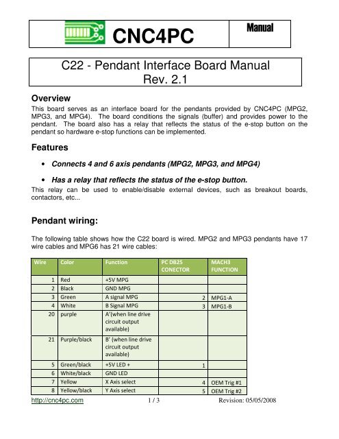
CNC4PCManual<strong>C22</strong> - <strong>Pendant</strong> <strong>Interface</strong> Board ManualRev. 2.1OverviewThis board serves as an interface board for the pendants provided by CNC4PC (MPG2,MPG3, and MPG4). The board conditions the signals (buffer) and provides power to thependant. The board also has a relay that reflects the status of the e-stop button on thependant so hardware e-stop functions can be implemented.Features• Connects 4 and 6 axis pendants (MPG2, MPG3, and MPG4)• Has a relay that reflects the status of the e-stop button.This relay can be used to enable/disable external devices, such as breakout boards,contactors, etc...<strong>Pendant</strong> wiring:The following table shows how the <strong>C22</strong> board is wired. MPG2 and MPG3 pendants have 17wire cables and MPG6 has 21 wire cables:Wire Color Function PC DB25CONECTORMACH3FUNCTION1 Red +5V MPG2 Black GND MPG3 Green A signal MPG 2 MPG1-A4 White B Signal MPG 3 MPG1-B20 purple A’(when line drivecircuit outputavailable)21 Purple/black B’ (when line drivecircuit outputavailable)5 Green/black +5V LED + 16 White/black GND LED7 Yellow X Axis select 4 OEM Trig #18 Yellow/black Y Axis select 5 OEM Trig #2http://cnc4pc.<strong>com</strong> 1 / 3 Revision: 05/05/2008
Shield9 Brown Z Axis select 6 OEM Trig #310 Brown/black 4 Axis select 7 OEM Trig #418 Pink 5(when select the5th axis) 12 OEM Trig #919 Pink/black 6(when select the6th axis) 13OEM Trig#1011 Gray X 1 Select 8 OEM Trig #512 Gray/black X10 Select 9 OEM Trig #613 Orange X100 Select 10 OEM Trig #714 Orange/black COM of scale selectand Axis select15 Light blue E stop C 15 OEM Trig #816 LightE stop CNBlue/black17 Red/black N.C, reserve forfuture useShield wireConnecting a 6 axis pendant:The board <strong>com</strong>es with a connector that receives the pendant. A brain file that runs the brain isprovided. Please note that the brain file is different from the brain file provided for otherexpansion boards, since the one is configured to the wiring of this board.The idea is that you should not use and the PC as a means of deactivating the system in theevent of an emergency. The board has a relay can be used as a means toactivate/deactivate hardware in a direct manner. The relay reflects the status of e-stop buttonon the pendant. The e-stop button is normally closed, when the button is not depressed thecircuit is closed and the relay is activated. That activation can be used to keep otherhardware active, such as breakout boards, contactors, or an arrangement of relay switchesthat can govern the safety of the system.Basic connection of the E-STOP RELAY. For more advanced connections check:http://cnc4pc.<strong>com</strong>/Tech_Docs/E-STOP_RELAY.pdfhttp://cnc4pc.<strong>com</strong> 2 / 3 Revision: 05/05/2008
Requirements:It requires a +5VDC@ 100mA power supply to operate.Dimensions:Disclaimer:Use caution. CNC machines are dangerous machines. DUNCAN USA, LLC or Arturo Duncanare not liable for any accidents resulting from the improper use of these devices.http://cnc4pc.<strong>com</strong> 3 / 3 Revision: 05/05/2008