C11T- MULTIFUNCTION CNC BOARD Rev. 2 - CNC4PC
C11T- MULTIFUNCTION CNC BOARD Rev. 2 - CNC4PC
C11T- MULTIFUNCTION CNC BOARD Rev. 2 - CNC4PC

Create successful ePaper yourself
Turn your PDF publications into a flip-book with our unique Google optimized e-Paper software.
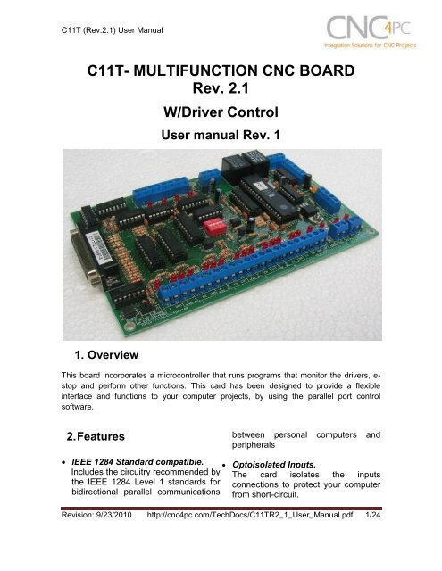
<strong>C11T</strong> (<strong>Rev</strong>.2.1) User Manual<strong>C11T</strong>- <strong>MULTIFUNCTION</strong> <strong>CNC</strong> <strong>BOARD</strong><strong>Rev</strong>. 2.1W/Driver ControlUser manual <strong>Rev</strong>. 11. OverviewThis board incorporates a microcontroller that runs programs that monitor the drivers, e-stop and perform other functions. This card has been designed to provide a flexibleinterface and functions to your computer projects, by using the parallel port controlsoftware.2. Featuresbetween personal computers andperipherals IEEE 1284 Standard compatible. Optoisolated Inputs.Includes the circuitry recommended by The card isolates the inputsthe IEEE 1284 Level 1 standards for connections to protect your computerbidirectional parallel communications from short-circuit.<strong>Rev</strong>ision: 9/23/2010 http://cnc4pc.com/TechDocs/<strong>C11T</strong>R2_1_User_Manual.pdf 1/24
<strong>C11T</strong> (<strong>Rev</strong>.2.1) User Manual Optoisolated Drivers Monitorcircuit. Buffered outputs. Outputs arebuffered through the use of highspeed and high current buffersallowing the card to output the signalswithout using the power from theparallel port. It can take the +3.3 or+5vdc signal from the parallel port anddeliver solid +5vdc at 24 milliamps. Microcontroller based SCHP.This board comes with amicrocontroller that allows theimplementation of a complex algorithmfor sampling and analyzing the SCHPsignal. Built-in Variable Speed Control.It has an optoisolated analog 0-10VDC output that will convert a stepsignal into an analog signal that canbe used to command a commercialVFD. This analog can be adjustedusing on-board potentiometer, so thisboard can be adjusted to othervoltages. Monitors E-Stop, Safety ChargePump, and Drivers (it onlymonitors (it only monitorsG320/340, G203, G210/201 ViperServomotor and Dugong drives atthis time). Enables and disables the drivers. Microcontroller Based MonitorSystem. Two Built-in ElectromechanicalRelays with NO and NC positions. Status LEDs on all inputs andoutput connections.No more guessing. You can SEE allyour signals. Save valuable time andbrainpower for <strong>CNC</strong>ing. To avoidremaining current to the main load(driver or other device), all theindicator LEDs are driven byindependent buffers of the ones thatdrive de output. Output pins 1, 2, 3, 4, 5, 6, 7, 8, 9,14, 16, 17. Input pins 10, 11, 12, 13, 15. The common terminal to pins 2-9can be ground or +5vdc. Forgetabout grounding problems. Easilyconnect your pin by using close byground connection. The board has aJumper that allows you to select ifthe common terminal to pins 2-9 willcarry a ground or +5vdc. External Enable Pin (E-Stop). Theboard has a pin that allows you toenable/disable all the outputs atonce. The board requires +5vdc inthe EN pin. If it is not present, it willsend all the outputs to ground. Youcan use this to enable or disable thesystem manually, or you can installan external Safety Charge Pump orother external safety monitoringdevice. This pin acts as hardwaredisable. Works directly with popular <strong>CNC</strong>hardware and software. Such as<strong>Rev</strong>ision: 9/23/2010 http://cnc4pc.com/TechDocs/<strong>C11T</strong>R2_1_User_Manual.pdf 2/24
<strong>C11T</strong> (<strong>Rev</strong>.2.1) User ManualGeckodrive,Rutex, Keling, Viper,Dugong, and parallel port controlsoftware, such as mach2, LinuxEMC2, and Turbo<strong>CNC</strong>. All TTL 5VDC signals. Interfacedirectly with parallel port interfaceproducts and other <strong>CNC</strong>4PC cards.5VDC (TTL) cards are very commonamong automation devices. Screw-On connections for allterminals. You only have to screwonthe wires to make all yourconnections. All pins can be used in aconcurrent manner.You can use all the input or outputpins in a concurrent manner. Forexample, if you are using output pin#1 to control the Built-inElectromechanical Relay, you canalso access that signal from theoutput pin on the board or from theDB25 connector for output. Eachconnection will not affect the othercurrent from the other connection.3. Specifications.OPTOISOLATED SINKING INPUTS SPECIFICATIONSMaximum operation frequency40KHzDIGITAL OUTPUT SPECIFICATIONSMaximum output voltage (5V power supply voltage) + 0.5VTypical output current24mAMaximum off-state voltaje0.44 VMaximum operation frequency4 MHzTypical signal delay10 nSTime of transition to high impedance state12 nS**Time passed since a low in the ENABLE input is detected and the outputs are disabled<strong>Rev</strong>ision: 9/23/2010 http://cnc4pc.com/TechDocs/<strong>C11T</strong>R2_1_User_Manual.pdf 3/24
<strong>C11T</strong> (<strong>Rev</strong>.2.1) User ManualRequirements:It requires a 5VDC @ 1.5 Amp power supply to operate.It requires an additional 5VDC @ 200mA power supply to power the drivermonitoring circuit if using G320/340 drivers. This to keep the ERR/RES terminalisolated. This power supply or it’s ground should not be used on anything else onthe wiring to keep the ground of the drivers isolated from the ground of the logic.WARNINGCheck the polarity and voltage of the external power source and connect the 5Vand GND. Overvoltage or reverse-polarity power applied to these terminals cancause damage to the board, and/or the power source.WARNING: This card must have the power supplied while it is connected tothe PC. If power is removed to the card while it is connected to the PC, noise canbe introduced to the output lines. This can create a dangerous situation as relaysor other devices that might be connected to this card, which could get activated.<strong>Rev</strong>ision: 9/23/2010 http://cnc4pc.com/TechDocs/<strong>C11T</strong>R2_1_User_Manual.pdf 4/24
<strong>C11T</strong> (<strong>Rev</strong>.2.1) User Manual4. Functional Block Diagrams4.1 Outputs 2-9 simplified functional block diagramFig. 1 Simplified functional block diagram for the outputs 2-9.Parallel Port coupling is done following IEEE 1284 standard recommendation. Theindicator led is driven by a different buffer.4.2 Outputs 1, 14, 16 and 17 simplified functional block diagramFig. 2 Simplified functional block diagram for the outputs 1, 14, 16 and 17.Note: “Internal Enable” = “E-Stop Pin” AND (“SCHP” OR “Bypassed SCHP”) AND ParallelPort connection.<strong>Rev</strong>ision: 9/23/2010 http://cnc4pc.com/TechDocs/<strong>C11T</strong>R2_1_User_Manual.pdf 5/24
<strong>C11T</strong> (<strong>Rev</strong>.2.1) User ManualThe “Internal Enable” is the result of an AND operation among the “E-Stop Pin”, the SCHPoperation mode selected by the user and the port connection to the PC parallel Port.4.3 Inputs simplified block diagramFig. 3 Simplified functional block diagram for the inputs.<strong>Rev</strong>ision: 9/23/2010 http://cnc4pc.com/TechDocs/<strong>C11T</strong>R2_1_User_Manual.pdf 6/24
<strong>C11T</strong> (<strong>Rev</strong>.2.1) User Manual5. Special Functions5.1 Safety Charge Pump “SCHP”. (Pin 17)This board takes advantage of Mach ability to send a specific frequency throughone of the pins of the parallel port when the program is in control of the system.<strong>CNC</strong> machinery can be very dangerous, and you could have a risk of the machinedoing something different that what you intend the machine to do if the programloses control of your system. Mach be can be programmed in a way, so when it is“in control”, it delivers a 12.5 KHz signal through one of the pins. This card lets youuse this signal to work as an On/Off switch for your system, enabling a powerfulsafety system for your equipment. If you ever had windows crash on you, then thiscard is for you. The port can also do weird things while the system is coming up, ordown.For Configuring the Charge Pump in Mach X: Use the dialog Config / Portsand pins / Output Signals. Enable the Charge Pump output and configures it as isshown in the Fig. 8 Next, press the apply button.Fig. 3. Charge Pump configuration<strong>Rev</strong>ision: 9/23/2010 http://cnc4pc.com/TechDocs/<strong>C11T</strong>R2_1_User_Manual.pdf 7/24
<strong>C11T</strong> (<strong>Rev</strong>.2.1) User ManualSelecting the SCHP operation modeThe onboard DIPSWITCH allows activating or deactivating the SCHP detectionfunction.SWITCH 2 ON: Activate the SCHP detection function.SWITCH 2 OFF: Deactivate the SCHP detection function.Note: When the Safety Charge Pump is activated, 5V in the E-Stop terminal and a validSCHP signal is present, Port 2 Pin 17 will go high. This high signal can be used to enableother external devices, such as enabling other Breakout Boards, or relays that wouldenable servos, VFDs, contactors, etc….<strong>Rev</strong>ision: 9/23/2010 http://cnc4pc.com/TechDocs/<strong>C11T</strong>R2_1_User_Manual.pdf 8/24
C32 (<strong>Rev</strong>. 1.1) User Manual5.2 Variable Speed Control. (pin 14)This function lets you control your spindle with step and direction signals, as if it wasan axis motor. It converts the step signal into an analog (0-10VDC) .A Variable Frequency Drive or Inverter works by modifying the frequency for ACmotors. You can control most of these devices with an external analog signal (0-10VDC). That is, if there is 5VDC coming into through the control signal, the motorwill run at 50% of full speed, if there was 10VDC, the motor will run at 100% of fullspeed. If there is no signal coming out, then the motor will stop.This function can also be used on many DC motor controllers by replacing thepotentiometer that controls the speed.Requirements:It requires a +12VDC@ 50mA power supply to operate.WARNING: To keep the output signals optoisolated, these must nothave common ground or connections to current with other circuits youare using.You will require a voltmeter to fine tune the analog.Wiring:Before connecting anything, please be sure to read your VFD’s manual andmake sure you understand all the safety issues.Please check the wiring guide and wiring samples here:http://cnc4pc.com/Tech_Docs/C6R5_WG.pdf andhttp://cnc4pc.com/Tech_Docs/C6R5_WS.pdfConfiguring the Control Software:It is strongly recommend you read your control software’s manual. You need toconfigure your control software to control the spindle as if it was an angular axis.This card requires a 25 KHz input signal in the pin 14 to deliver 10VDC. So you<strong>Rev</strong>ision: 9/14/2010 http://cnc4pc.com/TechDocs/C32R1_1_User_Manual.pdf 9/20
C32 (<strong>Rev</strong>. 1.1) User Manualhave to set the speed of the motor (spindle) at maximum. For acceleration valuesadjust them to where you feel comfortable. Keep in mind the acceleration of themotor must also be set in your VFD.For configuring Mach follow these steps:1. Go to Config / Ports&Pins / Motor Outputs. Enable the spindle and select the portand pins you wired for step and direction.Fig. 4. Ports&Pins configuration screenshot2. Go to Config / Ports&Pins / Spindle Setup. In the motor control box, check UseSpindle Motor Output and Step /Dir Motor. Under Pulley Ratios set the pulleyratios of the machine.<strong>Rev</strong>ision: 9/14/2010 http://cnc4pc.com/TechDocs/C32R1_1_User_Manual.pdf 10/20
C32 (<strong>Rev</strong>. 1.1) User ManualFig. 5. Spindle Setup screenshot.3. Go to Config / Motor Tuning / Spindle. On Steps per unit put 1,000, set velocity tomaximum. For Acceleration, choose the acceleration that you feel comfortablewith. Start slow, increase acceleration as you test your system. Under Step Pulselength, use a number from 3 to 5, but start with 3. This number is directlyproportional to the final voltage you will get in the analog output. Use this numberand the fine tuning pot to adjust the voltage you want to get at max speed.Fig. 6. Motor Tuning and Setup screenshot.After configuring the Mach, these steps should be followed.Step 1. Ensure that all external power sources are set to OFF.Step 2. Connect the power supply to the Power Inputs Connectors (X1).Step 3. Turn on the external suppliesStep 4. Connect a multimeter in the analog outputs connectors (X2) and make andfine tune this output:<strong>Rev</strong>ision: 9/14/2010 http://cnc4pc.com/TechDocs/C32R1_1_User_Manual.pdf 11/20
C32 (<strong>Rev</strong>. 1.1) User ManualMake sure that when you reach the maxspeed in the control software you get 10VDCout (X2). This voltage can vary dependingon many things, including the electricalproperties of parallel port or breakout boardyou are using, the length of the step pulseyour software is delivering, and the normal hior low status of your step pin. Play with thefine tuning pot in the card (X3), the normallyhi or low status of your pin, and the pulsewidth.5.3 Electromechanical relays. (Pin 1 and Pin 16)Electromechanical relays are very flexible because they can be used for AC or DCand come with NO and NC (Normally Open and Normally Closed) positions.ELECTROMECHANICAL RELAYS SPECIFICACTIONSMaximun Current (AC) 7A@240VAC; 10A@125VACMaximun Current (DC) 15A@24VDC; 10A@28VDCTable 2. Electromechanical Relays Specifications.5.4 Microcontroller based driver monitoring system.This board incorporates a microcontroller that runs programs that monitor thedrivers, e-stop and perform other functions.Functions:<strong>Rev</strong>ision: 9/14/2010 http://cnc4pc.com/TechDocs/C32R1_1_User_Manual.pdf 12/20
C32 (<strong>Rev</strong>. 1.1) User Manual Enables and disables the drivers. Monitors E-Stop. Monitors Safety Charge Pump, Monitors the Drivers errors pins. (it only monitors G320/340, G203, G210/201,Viper Servomotor and Dugong servo drives at this time). Indicates the fault source. Indicates the system Status.5.4.1 Configuration DIPSWITCHThe DIPSWITCH allows activating or deactivating the SCHP detection function,and selecting the driver to be monitored. SWITCH 1SWITCH 1 OFF: Delayed enable output (Port 2 Pin 17).SWITCH 1 ON: Non Delayed enable output (Port 2 Pin 17).The enable output will be activated when start the drivers enable process. A delayin the signal activation time could be added by selecting the OFF position in theDIPSWITCH 1. The table below shows the delay time for every supported driver.DRIVERDELAY (Sec.)G320/340 5G203 2G210/201 2Viper/Dugong 5 SWITCH 2SWITCH 2 ON: Activate the SCHP detection function<strong>Rev</strong>ision: 9/14/2010 http://cnc4pc.com/TechDocs/C32R1_1_User_Manual.pdf 13/20
<strong>C11T</strong> (<strong>Rev</strong>. 2.1) User ManualSWITCH 2 OFF: Deactivate the SCHP detection function SWITCH 3 and 4Select the driver you will use according to the below table.DRIVER DIP 3 DIP 4G320/G340 0 0G203 1 0G210/201 0 1Viper /Dugong 1 15.4.2 Program descriptionIn order to start the driver monitoring function it is necessary connecting the driverERR/RES (servo drivers) or EN (stepper driver) terminal to the RJ45 driverconnector pin 4.ERR/RES (servo drivers) or EN (stepper driver) descriptionsOperation Mode 1 (G320/G340)When the system starts, the board’s error/reset pins go to a low state (0V), makingsure the driver remains disabled. When SCHP and E-Stop function are checkedand validated and there is no fault signal coming from a driver, the system sends ahigh (5V) to the driver’s error/reset pins for about 5 seconds to enable the drivers.After that the system monitors the driver’s err/res pins. If a fault occurs on anydriver (0V in driver ERR/RES pin) or an external fault occurs (E-Stop or SCHPfault), the system stops and sends an e-stop signal to the controller. All outputs onthe board are disabled and the drivers will be disabled by sending a LOW (0V) tothe drivers ERR/RES pin. The system will remain that way until the conditions torestart are present again.Operation Mode 2 (G203).When the system starts, the board’s enable pin go to a HIGH state (5V). WhenSCHP and E-Stop function are checked and validated, the system send a LOW(0V) to the driver’s EN pin for about 2 Sec, enabling the drivers. If an external erroroccurs, the system stops, resets the <strong>CNC</strong> software and sends a HIGH (5V) to thedrivers EN pin. The system will remain that way until the conditions to restart arepresent again.Operation Mode 3 (G210/201).<strong>Rev</strong>ision: 9/23/2010 http://cnc4pc.com/TechDocs/<strong>C11T</strong>R2_1_User_Manual.pdf 14/24
<strong>C11T</strong> (<strong>Rev</strong>. 2.1) User ManualWhen the system starts, the board’s enable pin go to a LOW state (0V). WhenSCHP and E-Stop function are checked and validated, the system send a HIGH(5V) to the Drivers EN pin for about 2 Sec, enabling the Drivers. If an externalerror occurs, the system stops, resets the <strong>CNC</strong> software and sends a LOW (0V) tothe drivers EN pin. The system will remain that way until the conditions to restartare present again.Operation Mode 4 (Viper & Dugong).When the system starts, the board’s enable pin go to a low state (0V). This willdisable the drives. When SCHP and E-Stop function are checked and validatedand there is no fault signal coming from a driver, the system sends a high (5V) tothe driver’s Fault Output pin, enabling the drivers. After that the system monitorsthe driver’s Fault Output pin. If an error is generated in any driver (0V in driverFault Output pin) or an external error occurs, the system stops, resets the <strong>CNC</strong>software and sends a LOW (0V) to the drivers to ensure they remain disabled.LEDs indicator OperationFor example, when the GECKO DRIVE is first powered up, it will be necessary topush the momentary switch to START for 5 seconds. This will clear the power-onreset condition and extinguish the FAULT LED. The motor will then be enabled andthe drive will begin to operate. This START function is automatically done by thebuilt in microcontroller based circuit when the SCHP is validated, or when theboard is power up if the SCHP function is disabled by the user.The standby LED will light to indicate that the system is ready but disabled.There are 3 possible error sources, a driver fault, an E-STOP error and a SCHPerror.<strong>Rev</strong>ision: 9/23/2010 http://cnc4pc.com/TechDocs/<strong>C11T</strong>R2_1_User_Manual.pdf 15/24
<strong>C11T</strong> (<strong>Rev</strong>. 2.1) User ManualIf at any time after that a condition occurs that causes the GECKO SERVO DRIVEto “fault out”, such as not being able to complete a step command, the ERR/RESterminal will be activated, signaling the microcontroller an error has occurred. Inthis case the Standby LED indicator and the driver error LED indicator will lightup to indicate that an error has occurred in a driver.If the E-STOP button is pressed the Standby LED indicator and the E-STOP errorLED indicator will light up.If the SCHP detection function is activated, and the system is ready (STANDBYLED OFF), and an error has occurred with the SCHP signal, the Standby LEDindicator and the SCHP error LED indicator will light up.6. Wiring diagramsWhile this board supports only TTL +5VDC signals, different kind of sensors,switches using different voltages can be connected using the diagrams that follow:Note: The below wiring diagrams are an example, any input can be used for the connections.Fig. 10 Wiring diagram to connect switches.<strong>Rev</strong>ision: 9/23/2010 http://cnc4pc.com/TechDocs/<strong>C11T</strong>R2_1_User_Manual.pdf 16/24
<strong>C11T</strong> (<strong>Rev</strong>. 2.1) User ManualFig. 11 Wiring diagram to connect NPN open collector proximity sensors.For a 24V or 12V sensor, the recommended value for the external resistor R1 is4.7K Ohm.Fig. 12 Wiring diagram to connect in parallel NPN open collector proximity sensors.Note: External Supply GND should be connected to the <strong>C11T</strong> GND inputs terminal<strong>Rev</strong>ision: 9/23/2010 http://cnc4pc.com/TechDocs/<strong>C11T</strong>R2_1_User_Manual.pdf 17/24
<strong>C11T</strong> (<strong>Rev</strong>. 2.1) User ManualFig. 13 Wiring diagram to connect NPN proximity sensors with internal pull up resistor.Fig. 14 Wiring diagram to connect PNP open collector proximity sensorsConnecting PNP open collector proximity sensor with the <strong>C11T</strong>R2.1Board R Value (12V) R Value (24V)<strong>C11T</strong>R2.1 470Ω 1KΩTable 15. R value to Connect PNP open collector proximity sensor with the C33.<strong>Rev</strong>ision: 9/23/2010 http://cnc4pc.com/TechDocs/<strong>C11T</strong>R2_1_User_Manual.pdf 18/24
<strong>C11T</strong> (<strong>Rev</strong>. 2.1) User ManualFig. 16 Wiring diagram to do an “Auto Tool Zero”“Auto Tool Zero” with the <strong>C11T</strong>R2.1R Value (5V) R Value (12V) R Value (24V)200Ω 470Ω 1KΩ<strong>Rev</strong>ision: 9/23/2010 http://cnc4pc.com/TechDocs/<strong>C11T</strong>R2_1_User_Manual.pdf 19/24
<strong>C11T</strong> (<strong>Rev</strong>. 2.1) User Manual7. Troubleshooting.SYMPTOM 1: THE <strong>BOARD</strong> DOES NOT REACT TO THE SIGNAL.POSSIBLE CAUSEPOSSIBLE SOLUTIONS- Pin conflict or mach3 configuration.It is possible that the port addressused for the pin is not right, or thatthere is a pin conflict with the. That isthat you are using that same pin twice.(it could be assigned to a differentfunction).- The board does not like thewaveform it is getting. Somebreakout boards could invert thesignals or modify the pulse width.Changing the active low status of thepin used also inverts the waveform.- The signal or frequencies are notgetting to the board. It could be thecable or that you are passing thesignal through the same breakoutboard that you are enabling/disabling,so the outputs could be disabled, sothey will not get to the breakout board.- Problems with Mach3 PulseGeneration. Mach3 could haveinstallation problems (you did notrestart immediately after installation),or there could be something creating aconflict. Some dongle devices mightcause this, other software, likeQuickTime or drivers for touch screen.- Go to the device manager in windows,and check the memory address used forthe parallel port you are using. Usually itwill be 378 for LPT1. Check also thatthe port does not have a conflict. Thenin mach3, go to Ports & Pins / Port Setupand Axis Selection. Check the memoryaddress is correct.- Check that the pin you are using is notbeen used anywhere else in your setup.Got to motor output and output signals,and check all the entries.- Play with the active low status of the pinused for the frequency.- Try a different cable.- Test the pins in the cable (before theyreach the breakout board) with amultimeter.- Test this in a different PC.- Follow Art’s suggestions for optimizingup WinXP:http://www.machsupport.com/downloads/XP_Optimization.txt.SYMPTOM 2: THE OUTPUTS DO NOT GET ENABLED / NO SIGNALS ARECOMING OUT.<strong>Rev</strong>ision: 9/23/2010 http://cnc4pc.com/TechDocs/<strong>C11T</strong>R2_1_User_Manual.pdf 20/24
<strong>C11T</strong> (<strong>Rev</strong>. 2.1) User ManualPOSSIBLE CAUSE- The EN terminal (Enable Outputs) isnot enabled. The board requires to beexternally enabled.- The parallel cable is not wellconnected to the PC parallel port.POSSIBLE SOLUTIONS- Make sure you are providing +5vdc tothe EN terminal. This +5vdc can betaken from the terminal next to it.- Check if the parallel port is wellconnected to the PC.SYMPTOM 3: THERE IS NOISE IN THE SYSTEM, OR THE MOTORS DO NOTMOVE SMOOTHLY.POSSIBLE CAUSEPOSSIBLE SOLUTIONS- The board could be underpowered. - Make sure you are using a +5vdc1500mA power supply.- There could be a short that could bedraining the power to the board.- There could be an external noisesource that could be introducingnoise into the system.- Check that there are no hot spots in theboard or it’s connections.- Measure the board’s powerconsumption, it should be less than400mA (depending on the featuresused).- Blown chips could create an internalshort and end up drawing power that canaffect how other chips work.- Try using shielded cables.- Try to isolate VFDs or AC servos, etc.- Try using 103. 0.1mF caps between theI/O terminal and a ground of the board.SYMPTOM 4: A I/O PIN MIGHT NOT BE WORKING.POSSIBLE CAUSEPOSSIBLE SOLUTIONS- A chip may have gone bad. Thesebuffers could act as fuses for thesignals, and they can go bad becauseof noise spikes or even strong static.- These chips are inexpensive and readilyavailable. You can order them here:http://www.cnc4pc.com/Store/osc/index.php?cPath=38_43.- Carefully moving chips around andchecking if the problem moves aroundcould be a way of figuring out if this isthe case.- There could be a problem with the - Test this with a different PC or parallel<strong>Rev</strong>ision: 9/23/2010 http://cnc4pc.com/TechDocs/<strong>C11T</strong>R2_1_User_Manual.pdf 21/24
<strong>C11T</strong> (<strong>Rev</strong>. 2.1) User Manualparallel cable or parallel port.port.SYMPTOM 5: THE ANALOG OUTPUT DOES NOT REACH THE 10VDC.POSSIBLE CAUSEPOSSIBLE SOLUTIONS- Insufficient pulse width. It is possiblethat the signal pulse width is notenough to activate the optocouplers.- The signal is set active low or thebreakout board could be invertingthe signals.- In Mach X, go to Config / Motor Tuning /Spindle. Under Step Pulse lengthincrease this value, use a number from 3to 5, but start with 3.- In Mach X, go to Config / Ports&Pins /Motor Outputs. Change the active lowstatus of the pin used for step.<strong>Rev</strong>ision: 9/23/2010 http://cnc4pc.com/TechDocs/<strong>C11T</strong>R2_1_User_Manual.pdf 22/24
<strong>C11T</strong> (<strong>Rev</strong>. 2.1) User Manual8. Dimensions.All dimensions are in Millimeters.Disclaimer:Use caution. <strong>CNC</strong> machines can be dangerous machines. Neither DUNCAN USA, LLC norArturo Duncan are liable for any accidents resulting from the improper use of thesedevices. The M43 is not a fail-safe device and it should not be used in life support systemsor in other devices where its failure or possible erratic operation could cause propertydamage, bodily injury or loss of life.<strong>Rev</strong>ision: 9/23/2010 http://cnc4pc.com/TechDocs/<strong>C11T</strong>R2_1_User_Manual.pdf 23/24