C10- PARALLEL PORT INTERFACE CARD Rev. 10 - CNC4PC
C10- PARALLEL PORT INTERFACE CARD Rev. 10 - CNC4PC
C10- PARALLEL PORT INTERFACE CARD Rev. 10 - CNC4PC
- No tags were found...

You also want an ePaper? Increase the reach of your titles
YUMPU automatically turns print PDFs into web optimized ePapers that Google loves.
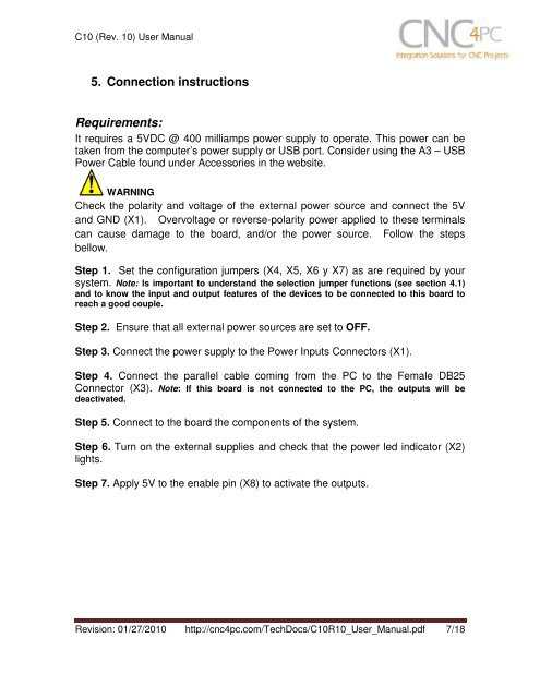
<strong>C<strong>10</strong></strong> (<strong>Rev</strong>. <strong>10</strong>) User Manual5. Connection instructionsRequirements:It requires a 5VDC @ 400 milliamps power supply to operate. This power can betaken from the computer’s power supply or USB port. Consider using the A3 – USBPower Cable found under Accessories in the website.WARNINGCheck the polarity and voltage of the external power source and connect the 5Vand GND (X1). Overvoltage or reverse-polarity power applied to these terminalscan cause damage to the board, and/or the power source. Follow the stepsbellow.Step 1. Set the configuration jumpers (X4, X5, X6 y X7) as are required by yoursystem. Note: Is important to understand the selection jumper functions (see section 4.1)and to know the input and output features of the devices to be connected to this board toreach a good couple.Step 2. Ensure that all external power sources are set to OFF.Step 3. Connect the power supply to the Power Inputs Connectors (X1).Step 4. Connect the parallel cable coming from the PC to the Female DB25Connector (X3). Note: If this board is not connected to the PC, the outputs will bedeactivated.Step 5. Connect to the board the components of the system.Step 6. Turn on the external supplies and check that the power led indicator (X2)lights.Step 7. Apply 5V to the enable pin (X8) to activate the outputs.<strong>Rev</strong>ision: 01/27/20<strong>10</strong> http://cnc4pc.com/TechDocs/<strong>C<strong>10</strong></strong>R<strong>10</strong>_User_Manual.pdf 7/18