C10- PARALLEL PORT INTERFACE CARD Rev. 10 - CNC4PC
C10- PARALLEL PORT INTERFACE CARD Rev. 10 - CNC4PC
C10- PARALLEL PORT INTERFACE CARD Rev. 10 - CNC4PC
- No tags were found...

Create successful ePaper yourself
Turn your PDF publications into a flip-book with our unique Google optimized e-Paper software.
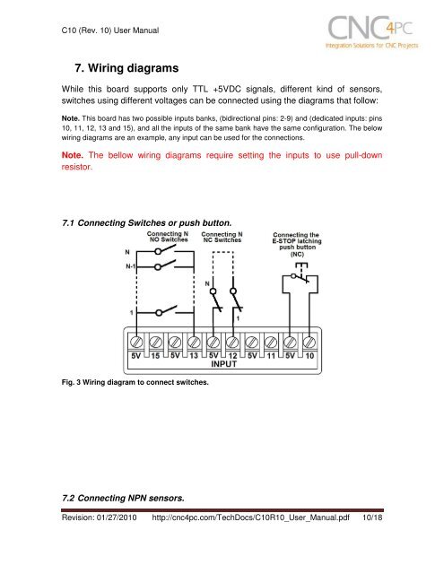
<strong>C<strong>10</strong></strong> (<strong>Rev</strong>. <strong>10</strong>) User Manual7. Wiring diagramsWhile this board supports only TTL +5VDC signals, different kind of sensors,switches using different voltages can be connected using the diagrams that follow:Note. This board has two possible inputs banks, (bidirectional pins: 2-9) and (dedicated inputs: pins<strong>10</strong>, 11, 12, 13 and 15), and all the inputs of the same bank have the same configuration. The belowwiring diagrams are an example, any input can be used for the connections.Note. The bellow wiring diagrams require setting the inputs to use pull-downresistor.7.1 Connecting Switches or push button.Fig. 3 Wiring diagram to connect switches.7.2 Connecting NPN sensors.<strong>Rev</strong>ision: 01/27/20<strong>10</strong> http://cnc4pc.com/TechDocs/<strong>C<strong>10</strong></strong>R<strong>10</strong>_User_Manual.pdf <strong>10</strong>/18