VoIP Acoustic Design - VLSI Solution
VoIP Acoustic Design - VLSI Solution
VoIP Acoustic Design - VLSI Solution

Create successful ePaper yourself
Turn your PDF publications into a flip-book with our unique Google optimized e-Paper software.
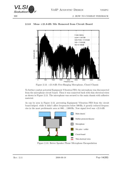
<strong>VLSI</strong><strong>Solution</strong>HHy<strong>VoIP</strong> <strong>Acoustic</strong> <strong>Design</strong>VSMPG2. HOW TO COMBAT FEEDBACK2.3.8 Meas +21.8 dB: Mic Removed from Circuit Board0−10−20F=466.1865HzLevel=−1.9277dBS/(N+THD)=−17.8183dBS/N=−17.8252dBHD=16.1388dBAmplitude (dB)−30−40−50−60−700 500 1000 1500 2000 2500 3000 3500 4000Frequency (Hz)Figure 2.12: +21.8 dB: Free-Hanging Microphone, Closed ChassisTo further combat potential Equipment Vibration FES, the microphone was disconnectedfrom the microphone circuit board. Then it was connected back with thin electrical wiresas shown in Figure 2.13. The microphone was secured to the main chassis with adhesivematerial.As can be seen in Figure 2.12, preventing Equipment Vibration FES from the circuitboard helped: while it didn’t affect frequencies below 500 Hz, it greatly reduced frequenciesin the most problematic area at 800. . . 1300 Hz. Now signal level was +21.8 dB.Main chassisRubber protector/directorMicrophoneMic pins + solderCircuit boardThin electrical wiresFigure 2.13: Better Speaker Phone Microphone EncapsulationRev. 2.11 2008-09-18 Page 14(22)