VoIP Acoustic Design - VLSI Solution
VoIP Acoustic Design - VLSI Solution
VoIP Acoustic Design - VLSI Solution

Create successful ePaper yourself
Turn your PDF publications into a flip-book with our unique Google optimized e-Paper software.
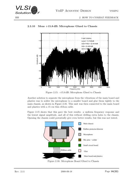
<strong>VLSI</strong><strong>Solution</strong>HHy<strong>VoIP</strong> <strong>Acoustic</strong> <strong>Design</strong>VSMPG2. HOW TO COMBAT FEEDBACK2.3.10 Meas +15.8 dB: Microphone Glued to Chassis0−10−20F=887.9395HzLevel=−13.7548dBS/(N+THD)=−23.4818dBS/N=−23.4853dBHD=5.7227dBAmplitude (dB)−30−40−50−60−700 500 1000 1500 2000 2500 3000 3500 4000Frequency (Hz)Figure 2.15: +15.8 dB: Microphone Glued to ChassisAnother solution to separate the microphone from the vibrations of the main board andplastics was to solder the microphone to a smaller board and glue them tightly to themain chassis, as shown in Figure 2.16. This unit was then connected to the main boardand plastics with a 15 cm thin ribbon cable.Figure 2.15 shows that this gave the best results: a uniform frequency response andthe lowest signal amplitude, and all of this without drilling extra holes to the chassis.Opening the chassis could potentially give even better results, but this was not tested.Main chassisRubber protector/directorMicrophoneMic pins + solderSmall circuit boardRibbon cableGlueMain board and plasticsFigure 2.16: Microphone Board Glued to ChassisRev. 2.11 2008-09-18 Page 16(22)