

20HLV16 - diagramas.diagram...
20HLV16 - diagramas.diagram...
20HLV16 - diagramas.diagram...
- No tags were found...

You also want an ePaper? Increase the reach of your titles
YUMPU automatically turns print PDFs into web optimized ePapers that Google loves.
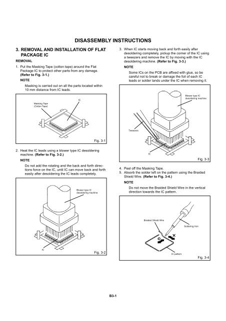
DISASSEMBLY INSTRUCTIONS3. REMOVAL AND INSTALLATION OF FLATPACKAGE ICREMOVAL1. Put the Masking Tape (cotton tape) around the FlatPackage IC to protect other parts from any damage.(Refer to Fig. 3-1.)NOTEMasking is carried out on all the parts located within10 mm distance from IC leads.3. When IC starts moving back and forth easily afterdesoldering completely, pickup the corner of the IC usinga tweezers and remove the IC by moving with the ICdesoldering machine. (Refer to Fig. 3-3.)NOTESome ICs on the PCB are affixed with glue, so becareful not to break or damage the foil of each ICleads or solder lands under the IC when removing it.Masking Tape(Cotton Tape)ICBlower type ICdesoldering machineTweezersFig. 3-12. Heat the IC leads using a blower type IC desolderingmachine. (Refer to Fig. 3-2.)NOTEDo not add the rotating and the back and forth directionsforce on the IC, until IC can move back and fortheasily after desoldering the IC leads completely.Blower type ICdesoldering machine4.5.ICFig. 3-3Peel off the Masking Tape.Absorb the solder left on the pattern using the BraidedShield Wire. (Refer to Fig. 3-4.)NOTEDo not move the Braided Shield Wire in the verticaldirection towards the IC pattern.Braided Shield WireSoldering IronICFig. 3-2IC patternFig. 3-4B3-1


