HWS Series - TDK-Lambda
HWS Series - TDK-Lambda
HWS Series - TDK-Lambda
- No tags were found...

Create successful ePaper yourself
Turn your PDF publications into a flip-book with our unique Google optimized e-Paper software.
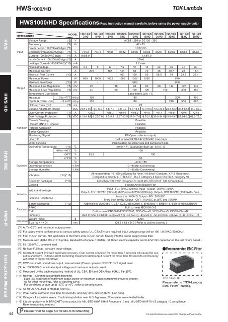
<strong>HWS</strong>1000/HD<strong>HWS</strong>1000/HD Specifications(Read instruction manual carefully, before using the power supply unit.)<strong>HWS</strong> <strong>HWS</strong> HD <strong>HWS</strong> ME <strong>HWS</strong>-PInstruction ManualITEMS/UNITS MODELInputOutputVoltage Range (*2) V AC85 - 265 or DC120 - 330Frequency (*2) Hz 47 - 63Power Factor (100/200VAC)(typ) (*1) 0.98/0.95Efficiency (100/200VAC)(typ) (*1) 71/73 76/78 79/81 80/82 82/85 83/85 85/87 85/88 86/88 85/88Current (100/200VAC)(typ) (*1) A 9.6/5.0 13.5/7.0Inrush Current (100/200VAC)(typ) (*3) A 20/40Leakage Current (100/240VAC) (*10) mA 1.2 maxNominal Voltage VDC 3.3 5 6 7.5 12 15 24 36 48 60Maximum Current A 200 167 134 88 70 46 30.7 23 18.4Maximum Peak Current (*13) A - 160 100 80 58.5 39 29.2 23.4Maximum Power W 660 1000 1002 1005 1056 1050 1104Maximum Peak Power (*13) W - 1200 1404Maximum Line Regulation (*5) mV 20 36 48 60 96 144 192 240Maximum Load Regulation (*6) mV 40 60 100 120 150 300 360Temperature CoefficientLess than 0.02% / MaximumRipple & Noise (*4)0 to +71 mVp-p 120 150 200 400-10 to 0 mVp-p 160 180 240 500 600Hold-up Time (typ) (*9) ms 20Voltage Adjustable Range VDC 2.64-3.96 4.0-6.0 4.8-7.2 6.0-9.0 9.6-14.4 12.0-18.0 19.2-28.8 28.8-43.2 38.4-52.8 48.0-66.0Over Current Protection (*7) A >210.0 >175.3 >168.0 >105.0 >84.0 >61.4 >40.9 >30.6 >24.5Over Voltage Protection (*8) VDC 4.12-4.62 6.25-7.0 7.5-8.4 9.37-10.5 15.0-17.4 18.7-21.8 30.0-34.8 45.0-49.7 55.2-60.0 69.0-75.0Remote SensingPossibleRemote ON/OFF ControlPossibleFunction Parallel OperationPossible<strong>Series</strong> OperationPossibleMonitoring SignalPF(Open collector output)Line DIPBuilt to meet SEMI-F47 (200VAC Line only)Other FunctionPCB Coating on solder side and component side.Operating Temperature (*11) -10 to + 71, Guarantee Start up -40 to -10-10 to +40°C 100+50°C 83.9 100+71°C 50Storage Temperature -40 to +85Environment Operating Humidity RH 10 - 90 (No Condensing)Storage Humidity RH 10 - 95 (No Condensing)Vibration (*14)(*15)At no operating, 10 - 55Hz (Sweep for 1min.) 19.6m/s² Constant, X,Y,Z 1hour each.Designed to meet MIL-STD-810F 514.5 Category 4 figure 514.5C-1, category 10Shock (In package) (*15) Less than 196.1m/s² Designed to meet MIL-STD-810F 516.5 Procedure ICoolingForced Air By Blower FanIsolationWithstand VoltageInput - FG : 2kVAC (20mA), Input - Output : 3kVAC (20mA)Output - FG : 500VAC (300mA), (60V model 651VAC(390mA)), Output - CNT:100VAC (100mA) for 1min.Isolation ResistanceMore than 100M Output - FG : 500VDCMore than 10M Output - CNT : 100VDC at 25 and 70%RHSafety Standards (*12) Approved by UL60950-1, CSA C22.2 No.60950-1, EN60950-1, EN50178. Built to meet DENAN.PFHCBuilt to meet IEC6100-3-2StandardsEMIBuilt to meet EN55011/EN55022-B, FCC-ClassB, VCCI-ClassB, CISPR-ClassB.Immunity Built to meet IEC61000-4-2(Level 2,3), -3(Level 3), -4(Level 3), -5(Level 3,4), -6(Level 3), -8(Level 4), -11Weight (max) g 3200MechanicalSize (WHD) mm 126.5 x 82 x 240 ( Refer to outline drawing )(*1) At Ta=25 and maximum output power.(*2) For cases where conformance to various safety specs (UL, CSA,EN) are required, input voltage range will be 100 - 240VAC(50/60Hz).(*3) First in-rush current. Not applicable to the first 0.2ms in-rush current flowing into the power supply noise filter.(*4) Measure with JEITA RC-9131A probe, Bandwidth of scope :100MHz. (at 100uF electric capacitor and 0.47uF film capacitor on the test fixture board.)(*5) 85 - 265VAC , constant load.(*6) No load-Full load, constant input voltage.(*7) Constant current limit with automatic recovery. Over current condition for more than 5 seconds will cause the outputto shutdown. Output current exceeding maximum rated output current for more than 10 seconds continuouslywill result to output shutdown.(*8) OVP circuit will shut down output, manual reset (Power cycle) or ON/OFF CNT signal reset.(*9) At 100/200VAC, nominal output voltage and maximum output current.(*10) Measured by the each measuring method of UL, CSA, EN and DENAN(at 60Hz), Ta=25.(*11) Ratings - Derating at standard mounting.- Load (%) is percent of maximum output power or maximum output current,whichever is greater.- As for other mountings, refer to derating curve.- For conditions of start up at -40 to 10, refer to derating curve.(*12) As for DENAN,built to meet at 100VAC.(*13) Peak output current is less than 10 seconds, and duty 35% max.(200VAC Line only)(*14) Category 4 exposure levels : Truck transportation over U.S. highways, Composite two-wheeled trailer.(*15) It is compulsory to fix BRACKET onto product for MIL-STD-810F 516.5 Procedure and MIL-STD-810F 514.5 category 10 compliance.Refer to mounting method.