HWS Series - TDK-Lambda
HWS Series - TDK-Lambda
HWS Series - TDK-Lambda
- No tags were found...

Create successful ePaper yourself
Turn your PDF publications into a flip-book with our unique Google optimized e-Paper software.
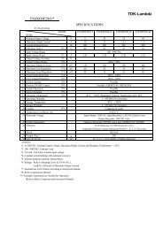
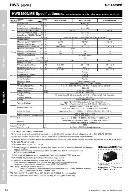
<strong>HWS</strong>1500/ME<strong>HWS</strong>1500/ME Specifications(Read instruction manual carefully, before using the power supply unit.)ITEMS/UNITSMODEL <strong>HWS</strong>1500-24/ME <strong>HWS</strong>1500-36/ME <strong>HWS</strong>1500-48/ME<strong>HWS</strong> <strong>HWS</strong> HD <strong>HWS</strong> ME <strong>HWS</strong>-PInstruction ManualInputOutputVoltage Range (*2) V AC85 - 265Frequency (*2) Hz 47 - 63Power Factor (100/230VAC)(typ) (*1) 0.98 / 0.94Efficiency (100/200VAC)(typ) (*1) % 84 / 88 86 / 90Current (100/200VAC)(typ) (*1) A 19.0 / 10.0Inrush Current (100/200VAC)(typ) (*3) A 20 / 40Leakage Current (*10) mA Less than 0.5. (0.2 (typ) at 100VAC / 0.4 (typ) at 230VAC)Nominal Voltage VDC 24 36 48Maximum Current (100/200VAC) A 65 / 70 42 / 46.5 32 / 32Maximum Peak Current (*13) A 105 70 -Maximum Power (100/200VAC) W 1560 / 1680 1512 / 1674 1536 / 1536Maximum Peak Power (*13) W 2520 -Maximum Line Regulation (*5) mV 96 144 192Maximum Load Regulation (*6) mV 144 150 288Temperature CoefficientLess than 0.02%/MaximumRipple & Noise (*4)0 to +70 mVp-p 200-10 to 0 mVp-p 240 400Hold-up Time (typ) (*9) ms 20Voltage Adjustable Range VDC 19.2 - 28.8 28.8 - 43.2 38.4 - 52.8Over Current Protection (*7) A >110.2 >73.5 >33.6Over Voltage Protection (*8) VDC 30.0 - 34.8 45.0-49.7 55.2 - 64.8Remote SensingPossibleRemote ON/OFF ControlPossibleFunctionParallel OperationPossible<strong>Series</strong> OperationPossibleMonitoring SignalPF (Open collector output)Line DIPBuilt to meet SEMI-F47 (200VAC Line only)Operating Temperature (*11) -10 to +70 ( -10 to +50: 100%, +60: 75%, +70: 50%), start up -20 to 70Storage Temperature -30 to +85Operating Humidity %RH 10 - 90 (No Condensing)Environment Storage Humidity %RH 10 - 95 (No Condensing)VibrationAt no operating, 10 - 55Hz (sweep for 1min.) 19.6m/s² constant, X, Y, Z 1hour each.Shock (In package)Less than 196.1m/s²CoolingForced air by blower fanWithstand VoltageIsolationIsolation ResistanceInput - FG : 2kVAC (20mA), Input - Output : 3kVAC (20mA)Output-FG : 500VAC (300mA), Output-CNT:100VAC (100mA) for 1min.More than 100M Output - FG : 500VDCMore than 10M Output - CNT : 100VDC at 25 and 70%RHSafety Standards (*12) Approved by UL60601-1, EN60601-1, CSA C22.2 No.601.1-M90 (C-UL)PFHCBuilt to meet IEC61000-3-2Voltage Fluctuations / Flicker EmissionsBuilt to meet IEC61000-3-3StandardsEMIApproved by EN55011 / EN55022-A, FCC-Class A, VCCI-Class AImmunityBuilt to meet IEC61000-4-2(Level 2,3), -3(Level 3), -4(Level 3),-5(Level 3,4), -6(Level 3), -8(Level 4), -11Weight (typ) g 3800MechanicalSize (W x H x D) mm 126.5 x 82 x 280 (Refer to outline drawing)(*1) At Ta=25 and maximum output power.(*2) For cases where conformance to various safety specs (UL, CSA, EN) are required, input voltage range will be 100 - 240VAC (50/60Hz).(*3) First in-rush current. Not applicable to the first 0.2ms in-rush current flowing into the power supply noise filter.(*4) Measure with JEITA RC-9131A probe, Bandwidth of scope :100MHz. (at 100uF electric capacitor and 0.47uF film capacitor on the test fixture board.)(*5) 85 - 265VAC, constant load.(*6) No load-Full load, constant input voltage.(*7) Constant current limit with automatic recovery. Over current condition for more than 5 seconds will cause the output to shutdown.Output current exceeding maximum rated output current for more than 10 seconds continuouslywill result to output shutdown.(*8) OVP circuit will shut down output, manual reset (Power cycle) or ON/OFF CNT signal reset.(*9) At 100/200VAC, nominal output voltage and maximum output current.(*10) Measured by the each measuring method of UL, EN and CSA (at 60Hz).When using it as a patient care equipment, all outer surfaces of the equipment shall beconstructed of nonconductive material. See clause 19.5DV.2 of UL60601-1.(*11) Ratings - Derating at standard mounting.- Load (%) is percent of maximum output power or maximum output current, whichever is greater.- As for other mountings, refer to derating curve.(*12) As for UL60601-1, EN60601-1 and CSA-C22.2 No.601.1-M90 (C-UL) basic insulation.(*13) Peak output current is less than 10 seconds, and duty 35% max. (200VAC Line only)