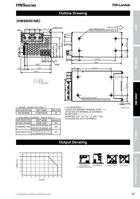
<strong>HWS</strong>600/ME<strong>HWS</strong>600/ME Specifications(Read instruction manual carefully, before using the power supply unit.)<strong>HWS</strong> <strong>HWS</strong> HD <strong>HWS</strong> ME <strong>HWS</strong>-PInstruction ManualITEMS/UNITSMODEL Voltage Range (*3) V AC85 - 265 or DC120 - 330Frequency (*3) Hz 47 - 63Power Factor (100/200VAC)(typ) (*2) 0.99 / 0.95Input Efficiency (100/200VAC)(typ) (*2) 80/83 81/84 82/85 83/86Current (100/200VAC)(typ) (*2) A 7.5/3.6 8.1 / 3.9Inrush Current (100/200VAC)(typ) A 20 / 40Leakage Current (*11) mA Less than 0.5. (0.12 (typ) at 100VAC / 0.34 (typ) at 230VAC)Nominal Voltage VDC 5 12 15 24 48Maximum Current (*1) A 120 53 43 27 (31) 13Maximum Power W 600 636 645 648 624Maximum Line Regulation (*6) mV 20 48 60 96 192OutputMaximum Load Regulation (*7) mV 30 72 90 144 288Temperature Coefficient (%)Less than 0.02% / CMaximum Ripple & Noise (0≤Ta≤70C) (*5) mVp-p 120 150 350Maximum Ripple & Noise (10≤Ta< 0C) (*5) mVp-p 180 200 400Hold-up Time (typ) (*10) ms 20Voltage Adjustable Range VDC 4.0 - 6.0 9.6 - 14.4 12.0 - 18.0 19.2 - 28.8 38.4 - 52.8Over Current Protection (*8) A >126 >55.7 >45.2 >31.4 >13.7Over Voltage Protection (*9) VDC 6.25 - 7.25 15.0 - 17.4 18.8 - 21.8 30.0 - 34.8 55.2 - 64.8Remote SensingPossibleRemote ON/OFF ControlPossibleFunctionParallel OperationPossible<strong>Series</strong> OperationPossibleMonitoring SignalPF (Open collector output)Line DIPDesigned to meet SEMI-F47 (200VAC Line only)Operating Temperature (*12) -10 to +70 (-10 - +50: 100%, +70: 50%)Storage Temperature -30 to +85Operating Humidity RH 10 - 90 (No dewdrop)Storage Humidity RH 10 - 95 (No dewdrop)EnvironmentAt no operating, 10 - 55Hz (sweep for 1min)Vibration19.6m/s² constant, X,Y,Z 1hour each.Shock (In package)Less than 196.1m/s²CoolingForced air by blower fanWithstand VoltageIsolationIsolation ResistanceInput - FG : 2.5kVAC (20mA), Input - Output : 3kVAC (20mA)Output - FG : 500VAC (100mA), Output - CNT : 100VAC (100mA) for 1minMore than 100M Output - FG : 500VDCMore than 10M Output - CNT : 100VDC at 25C and 70%RHSafety Standards (*13) Approved by UL60601-1, EN60601-1, CSA-C22.2 No601.1-M90PFHCDesigned to meet IEC61000-3-2Voltage Fluctuations / Flicker EmissionsDesigned to meet IEC61000-3-3StandardsEMIDesigned to meet EN55011/EN55022-A, FCC-A, VCCI-AImmunityDesigned to meet IEC61000-4-2(Level 3), -3(Level 3), -4(Level 3),-5(Level 3,4), -6(Level 3), -8(Level 4), -11Weight (typ) g 1600MechanicalSize (W x H x D) mm 100 x 82 x 165 (Refer to outline drawing)(*1) ( ): Peak output current at 200VAC. Operating time at peak output is less than 10 sec, duty is less than 35%.(*2) At 100/200VAC, Ta=25C and maximum output power.(*3) For cases where conformance to various safety specs (UL, CSA, EN) are required, to be described as 100 - 240VAC (50/60Hz).(*4) Not applicable for the inrush current to noise filter for less than 0.2ms.Inrush current is 30A (typ) when PFHC start-up.(*5) Measure with JEITA RC-9131A probe, bandwidth of scope: 100MHz.(*6) 85 - 265VAC, constant load.(*7) No load - full load, constant input voltage.(*8) Constant current limit with automatic recovery.Avoid to operate at over load or short circuit condition for more than 30 seconds.(*9) OVP circuit will shut the output down, manual reset (CNT reset or re-power on).(*10) At 100/200VAC, nominal output voltage and maximum output current.(*11) Measured by the each measuring method of UL, EN, and CSA (at 60Hz), Ta=25C.When using it as a patient care equipment, all outer surfaces of the equipment shall beconstructed of nonconductive material. See clause 19.5DV.2 of UL60601-1.(*12) Ratings - Derating at standard mounting. Refer to output derating curve.- Load (%) is percent of maximum output power or maximum output current, whichever is greater.(*13) As for UL60601-1, EN60601-1 and CSA-C22.2 No601.1-M90, basic insulation.
<strong>HWS</strong>600/MEOutline Drawing == SIGNAL CONNECTOR USED ==PART DESCRIPTIONPIN HEADERPART NAMES12B-PHDSS MANUFACTJST== MATCHING HOUSINGS , PINS & TOOL ==PART DESCRIPTIONSOCKET HOUSINGTERMINAL PINSHAND CRIMPING TOOLPART NAMEPHDR-12VSSPHD-002T-P0.5(AWG2824)SPHD-001T-P0.5(AWG2622)YRS-620(SPHD-002T-P0.5)YC-610R(SPHD-001T-P0.5)MANUFACTJSTJSTJST == ACCESSORIES ==*COVER FOR BARRIER TERMINAL STRIP -----1(ATTACHED ON TERMINAL AT SHIPMENT)*SHORT PIECE --------------------1SHORTING +Vm+S, -Vm-S, CNTTOG(ATTACHED ON CN1 AT SHIPMENT)Output Derating <strong>HWS</strong> <strong>HWS</strong> HD <strong>HWS</strong> ME <strong>HWS</strong>-P Instruction Manual
- Page 2 and 3:
HWSSeriesWIDE SELECTION OF LINE UP
- Page 4 and 5:
HWSSeriesHWS/MEAC/DC Switching powe
- Page 6 and 7:
HWSSpecificationsHWS15 8HWS30 10HWS
- Page 8 and 9:
HWS 15HWS15 Specifications(Read ins
- Page 10 and 11:
HWS 30HWS30 Specifications(Read ins
- Page 12 and 13: HWS 50HWS50 Specifications(Read ins
- Page 14 and 15: HWS 80HWS80 Specifications(Read ins
- Page 16 and 17: HWS 100HWS100 Specifications(Read i
- Page 18 and 19: HWS 150HWS150 Specifications(Read i
- Page 20 and 21: HWS 300HWS300 Specifications(Read i
- Page 22 and 23: HWS 600HWS600 Specifications(Read i
- Page 24 and 25: HWS 1000HWS1000 Specifications(Read
- Page 26 and 27: HWS 1500HWS1500 Specifications(Read
- Page 28 and 29: HWS 1800THWS1800T Specifications(Re
- Page 31 and 32: HWS/HD UL60590-1/CSA C22.2 No.6
- Page 33 and 34: HWS30/HDOutline Drawing
- Page 35 and 36: HWS50/HDOutline Drawing =
- Page 37 and 38: HWS100/HDOutline DrawingACCESSORIES
- Page 39 and 40: HWS150/HDOutline Drawing
- Page 41 and 42: HWS300/HDOutline Drawing == NOT
- Page 43 and 44: HWS600/HDOutline Drawing == SIGNA
- Page 45 and 46: HWS1000/HDOutline Drawing
- Page 47 and 48: HWS1500/HDOutline Drawing NOTESA:
- Page 49 and 50: HWS1800T/HDOutline Drawing
- Page 51 and 52: HWS/ME
- Page 53 and 54: HWS30/MEOutline Drawing Output
- Page 55 and 56: HWS50/MEOutline DrawingOutput Derat
- Page 57 and 58: HWS100/MEOutline Drawing
- Page 59 and 60: HWS150/MEOutline Drawing
- Page 61: HWS300/MEOutline Drawing
- Page 65 and 66: ELHWS1000/MEOutline Drawing N (AC
- Page 67: HWS1500/MEOutline Drawing
- Page 70 and 71: HWS300PHWS300P SpecificationsITEMS/
- Page 72 and 73: HWS600PHWS600P SpecificationsITEMS/
- Page 74 and 75: HWS 15 - 150Block DiagramHWS HWS HD
- Page 76 and 77: HWS 1500, 1800TBlock DiagramHWS HWS
- Page 78 and 79: Instruction ManualHWS HWS HD HWS ME
- Page 80 and 81: HWS 15, 30, 50, 80, 100, 150HWS HWS
- Page 82 and 83: HWS 15, 30, 50, 80, 100, 150HWS HWS
- Page 84 and 85: HWS 15, 30, 50, 80, 100, 150HWS HWS
- Page 86 and 87: HWS 300, 600HWS HWS HD HWS ME HWS-P
- Page 88 and 89: Instruction ManualHWS HWS HD HWS ME
- Page 90 and 91: HWS 300, 600HWS HWS HD HWS ME HWS-P
- Page 92 and 93: HWS 300, 600HWS HWS HD HWS ME HWS-P
- Page 94 and 95: HWS 1000HWS HWS HD HWS ME HWS-P
- Page 96 and 97: HWS 1000HWS HWS HD HWS ME HWS-P
- Page 98 and 99: Instruction ManualHWS HWS HD HWS ME
- Page 100 and 101: HWS 1000HWS HWS HD HWS ME HWS-P
- Page 102 and 103: HWS 1000HWS HWS HD HWS ME HWS-PInst
- Page 104 and 105: HWS 1500HWS 1500 Series Instruction
- Page 106 and 107: HWS 1500HWS HWS HD HWS ME HWS-PInst
- Page 108 and 109: HWS 1500HWS HWS HD HWS ME HWS-PInst
- Page 110 and 111: HWS 1500HWS HWS HD HWS ME HWS-P
- Page 112 and 113:
HWS 1500HWS HWS HD HWS ME HWS-P
- Page 114 and 115:
HWS 1800THWS HWS HD HWS ME HWS-P
- Page 116 and 117:
HWS 1800T HWS HWS HD HWS M
- Page 118 and 119:
Instruction ManualHWS HWS HD HWS ME
- Page 120 and 121:
HWS 1800THWS HWS HD HWS ME HWS-P
- Page 122 and 123:
HWS 1800THWS HWS HD HWS ME HWS-PIns
- Page 124 and 125:
HWS 300P, 600PHWS300P-600P Series I
- Page 126 and 127:
HWS 300P, 600PHWS HWS HD HWS ME HWS
- Page 128 and 129:
HWS 300P, 600PHWS HWS HD HWS ME HWS
- Page 130 and 131:
HWS 300P, 600PHWS HWS HD HWS ME HWS
- Page 132 and 133:
HWS 300P, 600PHWS HWS HD HWS ME HWS