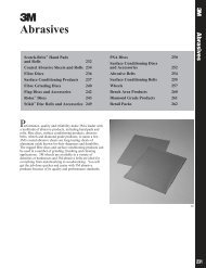
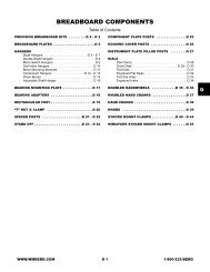
A s = π (D 2 H – D 2 h )Effect of Loading Planes4+ π D J D– 1 H l J+ l J 28 (DH )( 5 100)When the joint diameter D J is equal to or greater than 3D H :A s = π [(D H + 0.1 l J ) 2 – D 2 h ]4These formulate have been verified in laboratoriesby finite element method and by experiments.Fig. 6 shows joint diagrams for springy bolt andstiff joint and for a stiff bolt and springy joint. Thesediagrams demonstrate the desirability of designing withspringy bolt and a stiff joint to obtain a low additionalbolt load F eB and thus a low alternating stress.The Force RatioDue to the geometry of the joint diagram, Fig. 7,F eB =K e K BK B + K JKDefining Φ = BK B + K JF eB = F e Φ andΦ, called the Force Ratio, = F eBF eFor complete derivation of Φ, see Fig. 7.To assure adequate fatigue strength of the selectedfastener the fatigue stress amplitude of the bolt resultingfrom an external load F e is computed as follows:σ B = ± F eB/2orA mσ B = ±Φ F e2 A mThe joint diagram in Fig 3, 6 and 7 is applicable onlywhen the external load F e is applied at the same loadingplanes as the preloaded F i , under the bolt head and thenut. However, this is a rare case, because the externalload usually affects the joint somewhere between thecenter of the joint and the head and the nut.When a preloaded joint is subjected to an externalload F e at loading planes 2 and 3 in Fig. 8, F e relieves thecompression load of the joint parts between planes 2and 3. The remainder of the system, the bolt and thejoint parts between planes 1-2 and 3-4, feel additionalload due to F e applied planes 2 and 3, the joint materialbetween planes 2 and 3 is the clamped part and all otherjoint members, fastener and remaining joint material,are clamping parts. Because of the location of the loadingplanes, the joint diagram changes from black lineto the blue line. Consequently, both the additional boltload F B max decrease significantly when the loading planesof F e shift from under the bolt head and nut toward thejoint center.Determination of the length of the clamped parts is,however, not that simple. First, it is assumed that theexternal load is applied at a plane perpendicular to thebolt axis. Second, the distance of the loading planesfrom each other has to be estimated. This distance maybe expressed as the ratio of the length of clamped partsto the total joint length. Fig. 9 shows the effect of twodifferent loading planes on the bolt load, both jointshaving the same preload F i and the same external loadF e . The lengths of the clamped parts are estimated tobe 0.75l J for joint A, and 0.25l J for joint B.In general, the external bolt load is somewherebetween F eB = 1ΦF e for loading planes under head andnut and F eB = 0ΦF e = 0 when loading planes are in thejoint center, as shown in Fig. 10. To consider the loadingplanes in calculation, the formula:F e2F e2F e2F e2F e2F e2F e2F e2Fig. 6 Joint diagram of a springy bolt in a stiff joint (A), is compared to a diagram of a stiff bolt in a springy joint (B).Preload F i and external load F e are the same but diagrams show that alternating bolt stresses are significantly lowerwith a spring bolt in a stiff joint.58
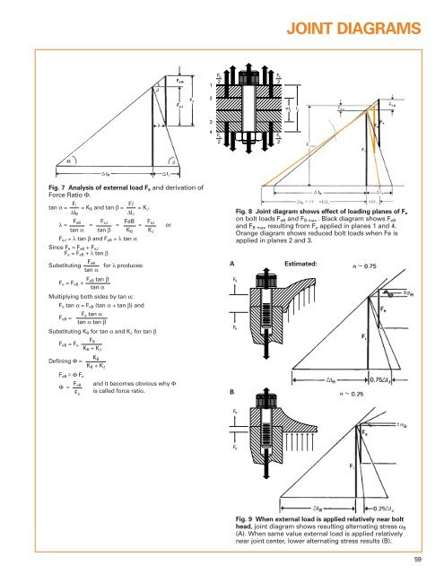
JOINT DIAGRAMSF e2F e212nl jI j34F e2F e2Fig. 7 Analysis of external load F e and derivation ofForce Ratio Φ.F itan α = = K B and tan β = Fi = K J∆l B∆l Jλ =F eB F= eJ FeB F = = eJ ortan α tan β K B K JF eJ = λ tan β and F eB = λ tan αSince F e = F eB + F eJF e = F eB + λ tan βSubstitutingF eBtan αfor λ produces:F e = F eB + F eB tan βtan αMultiplying both sides by tan α:F e tan α = F eB (tan α + tan β) andFF eB = e tan αtan α tan βSubstituting K B for tan α and K J for tan βAFig. 8 Joint diagram shows effect of loading planes of F eon bolt loads F eB and F B max . Black diagram shows F eBand F B max resulting from F e applied in planes 1 and 4.Orange diagram shows reduced bolt loads when Fe isapplied in planes 2 and 3.F eF eEstimated:F eB = F eDefining Φ =F BK B + K JK BK B + K JF eB= Φ F eΦ = F eBF eand it becomes obvious why Φis called force ratio.BF eF eFig. 9 When external load is applied relatively near bolthead, joint diagram shows resulting alternating stress α B(A). When same value external load is applied relativelynear joint center, lower alternating stress results (B).59