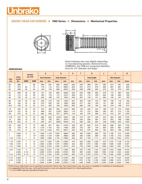
SOCKET HEAD CAP SCREWS 1960 Series Dimensions Mechanical PropertiesH30°TG"LT" THREAD LENGTHUNBUSAAF DAPPROX. 45°JLENGTHDIMENSIONSHead markings may vary slightly dependingon manufacturing practice. Diamond knurls,UNBRAKO, and UNB are recognized identificationsfor 1/4” diameter and larger.threadsA D G T H J F LTbasic per inchnom. screwhead diameter body diameter head height filet diametersize dia. UNRC UNRF max. min. max. min. min. min. max. min. nom. max. min basic#0 .060 – 80 .096 .091 .060 .0568 .020 .025 .060 .057 .050 .074 .051 .500#1 .073 64 72 .118 .112 .073 .0695 .025 .031 .073 .070 .062 .087 .061 .625#2 .086 56 64 .140 .134 .086 .0822 .029 .038 .086 .083 .078 .102 .073 .625#3 .099 48 56 .161 .154 .099 .0949 .034 .044 .099 .095 .078 .115 .084 .625#4 .112 40 48 .183 .176 .112 .1075 .038 .051 .112 .108 .094 .130 .094 .750#5 .125 40 44 .205 .198 .125 .1202 .043 .057 .125 .121 .094 .145 .107 .750#6 .138 32 40 .226 .218 .138 .1329 .047 .064 .138 .134 .109 .158 .116 .750#8 .164 32 36 .270 .262 .164 .1585 .056 .077 .164 .159 .141 .188 .142 .875#10 .190 24 32 .312 .303 .190 .1840 .065 .090 .190 .185 .156 .218 .160 .8751/4 .250 20 28 .375 .365 .250 .2435 .095 .120 .250 .244 .188 .278 .215 1.0005/16 .312 18 24 .469 .457 .3125 .3053 .119 .151 .312 .306 .250 .347 .273 1.1253/8 .375 16 24 .562 .550 .375 .3678 .143 .182 .375 .368 .312 .415 .331 1.2507/16 .437 14 20 .656 .642 .4375 .4294 .166 .213 .437 .430 .375 .484 .388 1.3751/2 .500 13 20 .750 .735 .500 .4919 .190 .245 .500 .492 .375 .552 .446 1.5009/16 .562 12 18 .843 .827 .5625 .5538 .214 .265 .562 .554 .438 .6185 .525 1.6255/8 .625 11 18 .938 .921 .625 .6163 .238 .307 .625 .616 .500 .689 .562 1.7503/4 .750 10 16 1.125 1.107 .750 .7406 .285 .370 .750 .740 .625 .828 .681 2.0007/8 .875 9 14 1.312 1.293 .875 .8647 .333 .432 .875 .864 .750 .963 .798 2.2501 1.000 8 12 1.500 1.479 1.000 .9886 .380 .495 1.000 .988 .750 1.100 .914 2.5001 1.000 – 14* 1.500 1.479 1.000 .9886 .380 .495 1.000 .988 .750 1.100 .914 2.5001 1/8 1.125 7 12 1.688 1.665 1.125 1.1086 .428 .557 1.125 1.111 .875 1.235 1.023 2.8121 1/4 1.250 7 12 1.875 1.852 1.250 1.2336 .475 .620 1.250 1.236 .875 1.370 1.148 3.1251 3/8 1.375 6 12 2.062 2.038 1.375 1.3568 .523 .682 1.375 1.360 1.000 1.505 1.256 3.4371 1/2 1.500 6 12 2.250 2.224 1.500 1.4818 .570 .745 1.500 1.485 1.000 1.640 1.381 3.7501 3/4 1.750 5 12 2.625 2.597 1.750 1.7295 .665 .870 1.750 1.734 1.250 1.910 1.609 4.3752 2.000 4 1/2 12 3.000 2.970 2.000 1.9780 .760 .995 2.000 1.983 1.500 2.180 1.843 5.0002 1/4 2.250 4 1/2 12 3.375 3.344 2.250 2.2280 .855 1.120 2.250 2.232 1.750 2.450 2.093 5.6252 1/2 2.500 4 12 3.750 3.717 2.500 2.4762 .950 1.245 2.500 2.481 1.750 2.720 2.324 6.2502 3/4 2.750 4 12 4.125 4.090 2.750 2.7262 1.045 1.370 2.750 2.730 2.000 2.990 2.574 6.8753 3.000 4 12 4.500 4.464 3.000 2.9762 1.140 1.495 3.000 2.979 2.250 3.260 2.824 7.500Performance data listed are for standard production items only. Non-stock items may vary due to variables in methods of manufacture.It is suggested that the user verify performance on any non-standard parts for critical applications.* 1-14 is UNRS (special) standard thread form.6
SOCKET HEAD CAP SCREWS1960 Series Dimensions Mechanical Properties Application DataNOTESTypical values for test specimens:Material: ASTM A574 – alloy steelASTM F837 – stainless steelDimensions: ANSI/ASME B18.3Elongation in 2 inches:Hardness: Alloy Steel – Rc 38-43Reduction of area:Stainless Steel – Rb 80 – Rc 33Concentricity: Body to head O.D. – within 2% of body diameter T.I.R. or .006 T.I.R.whichever is greater. Body to hex socket – (sizes through 1/2”) – within 3% ofbody diameter T.I.R. or .005 T.I.R. whichever is greater; (sizes over 1/2” – within6% of body diameter).The plane of the bearing surface shall be perpendicular to the axis of the screwwithin a maximum deviation of 1°.For body and grip lengths see pages 8 and 9.Thread Class: #0 through 1” dia. – 3A; over 1” dia. – 2A.AlloySteelStainlessSteel10% min. 10% min.35% min. 30% min.MECHANICAL PROPERTIESALLOY STEELSTAINLESS STEELsingle recommended seatingrecommended seat-tensile strength tensile yield sheartorque* in-lbs tensile strengthing torque* in-lbspounds strength strength strengthpoundssingleUNRC UNRFnom.psi psi of bodytensile tensile shearUNRC UNRFsize UNRC UNRF min. min. lbs. min. plain plain UNRC UNRF strength strength strength plain plain#0 – 342 190,000 170,000 320 – 3 – 171 95,000 30,000 130 – 1.3#1 499 528 190,000 170,000 475 5 5 250 264 95,000 30,000 190 2.0 2.3#2 702 749 190,000 170,000 660 7 8 352 374 95,000 30,000 260 3.8 4#3 925 994 190,000 170,000 875 12 13 463 497 95,000 30,000 350 5.7 6#4 1,150 1,260 190,000 170,000 1,120 18 19 574 628 95,000 30,000 440 8.0 9#5 1,510 1,580 190,000 170,000 1,400 24 25 756 789 95,000 30,000 550 12 14#6 1,730 1,930 190,000 170,000 1,700 34 36 864 964 95,000 30,000 670 15 17#8 2,660 2,800 190,000 170,000 2,400 59 60 1,330 1,400 95,000 30,000 850 28 29#10 3,330 3,800 190,000 170,000 3,225 77 91 1,660 1,900 95,000 30,000 1,280 40 451/4 6,050 6,910 190,000 170,000 5,600 200 240 3,020 3,460 95,000 30,000 2,200 95 1105/16 9,960 11,000 190,000 170,000 8,750 425 475 4,980 5,510 95,000 30,000 3,450 170 1903/8 14,700 16,700 190,000 170,000 12,600 750 850 7,360 8,350 95,000 30,000 4,470 300 3457/16 20,200 22,600 190,000 170,000 17,100 1,200 1,350 10,100 11,300 95,000 30,000 6,760 485 5451/2 27,000 30,400 190,000 170,000 22,350 1,850 2,150 13,500 15,200 95,000 30,000 8,840 750 8509/16 32,800 36,500 180,000 155,000 28,300 2,500 2,700 17,300 19,300 95,000 30,000 11,200 920 1,0505/8 40,700 46,100 180,000 155,000 34,950 3,400 3,820 21,500 24,300 95,000 30,000 13,800 1,270 1,4503/4 60,200 67,100 180,000 155,000 47,700 6,000 6,800 31,700 35,400 95,000 30,000 19,850 2,260 2,5207/8 83,100 91,700 180,000 155,000 64,000 8,400 9,120 44,000 48,400 95,000 30,000 27,100 3,790 4,1801 109,000 119,000 180,000 155,000 84,800 12,500 13,200 57,600 63,000 95,000 30,000 35,300 5,690 6,2301 – 122,000 180,000 155,000 107,000 – 13,9001-1/8 137,000 154,000 180,000 155,000 214,000 14,900 16,6001-1/4 175,000 193,000 180,000 155,000 132,500 25,000 27,0001-3/8 208,000 237,000 180,000 155,000 160,000 33,000 35,0001-1/2 253,000 285,000 180,000 155,000 190,500 43,500 47,0001-3/4 342,000 394,000 180,000 155,000 259,500 71,500 82,5002 450,000 521,000 180,000 155,000 339,000 108,000 125,0002-1/4 585,000 664,000 180,000 155,000 429,000 155,000 186,0002-1/2 720,000 828,000 180,000 155,000 530,000 215,000 248,0002-3/4 888,000 1,006,000 180,000 155,000 641,000 290,000 330,0003 1,074,000 1,204,000 180,000 155,000 763,000 375,000 430,000*Seating torques for alloy steel calculated in accordance with VDI 2230, “Systematic Calculation of High Duty Bolted Joints,” to induce approximately120,000 PSI in the screw threads through 0.500-inch diameter, and 115,000 PSI over 0.500-inch diameter. Seating torques for stainlesssteel are calculated to induce approximately 40,000 PSI stress. Values are for plain screws. For cadmium plated screws, multiply recommendedseating torque by .75; for zinc plated screws multiply by 1.40. See note, page 1.See Technical Guidelines section for additional information on torques, installation, and hole preparation.7