Wireless Thermostat Installation Guide and the Control4
Wireless Thermostat Installation Guide and the Control4
Wireless Thermostat Installation Guide and the Control4

Create successful ePaper yourself
Turn your PDF publications into a flip-book with our unique Google optimized e-Paper software.
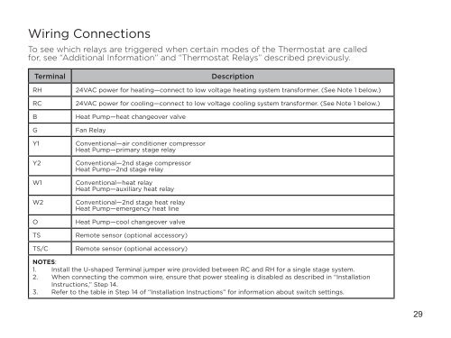
Wiring ConnectionsTo see which relays are triggered when certain modes of <strong>the</strong> <strong>Thermostat</strong> are calledfor, see “Additional Information” <strong>and</strong> “<strong>Thermostat</strong> Relays” described previously.TerminalRHRCBGY1Y2W1W2OTSTS/CDescription24VAC power for heating—connect to low voltage heating system transformer. (See Note 1 below.)24VAC power for cooling—connect to low voltage cooling system transformer. (See Note 1 below.)Heat Pump—heat changeover valveFan RelayConventional—air conditioner compressorHeat Pump—primary stage relayConventional—2nd stage compressorHeat Pump—2nd stage relayConventional—heat relayHeat Pump—auxiliary heat relayConventional—2nd stage heat relayHeat Pump—emergency heat lineHeat Pump—cool changeover valveRemote sensor (optional accessory)Remote sensor (optional accessory)NOTES:1. Install <strong>the</strong> U-shaped Terminal jumper wire provided between RC <strong>and</strong> RH for a single stage system.2. When connecting <strong>the</strong> common wire, ensure that power stealing is disabled as described in “<strong>Installation</strong>Instructions,” Step 14.3. Refer to <strong>the</strong> table in Step 14 of “<strong>Installation</strong> Instructions” for information about switch settings.29