fem modelling of a bellows and a bellows- based micromanipulator
fem modelling of a bellows and a bellows- based micromanipulator
fem modelling of a bellows and a bellows- based micromanipulator

You also want an ePaper? Increase the reach of your titles
YUMPU automatically turns print PDFs into web optimized ePapers that Google loves.
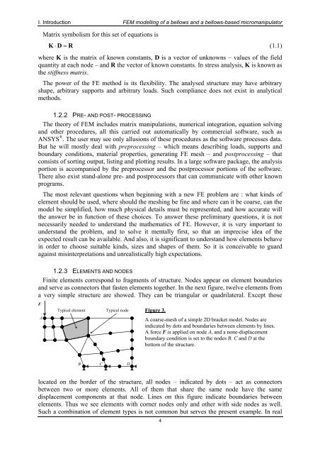
I. Introduction FEM <strong>modelling</strong> <strong>of</strong> a <strong>bellows</strong> <strong>and</strong> a <strong>bellows</strong>-<strong>based</strong> <strong>micromanipulator</strong>Matrix symbolism for this set <strong>of</strong> equations isK ⋅ D = R(1.1)where K is the matrix <strong>of</strong> known constants, D is a vector <strong>of</strong> unknowns – values <strong>of</strong> the fieldquantity at each node – <strong>and</strong> R the vector <strong>of</strong> known constants. In stress analysis, K is known asthe stiffness matrix.The power <strong>of</strong> the FE method is its flexibility. The analysed structure may have arbitraryshape, arbitrary supports <strong>and</strong> arbitrary loads. Such compliance does not exist in analyticalmethods.1.2.2 PRE- AND POST- PROCESSINGThe theory <strong>of</strong> FEM includes matrix manipulations, numerical integration, equation solving<strong>and</strong> other procedures, all this carried out automatically by commercial s<strong>of</strong>tware, such asANSYS ® . The user may see only allusions <strong>of</strong> these procedures as the s<strong>of</strong>tware processes data.But he will mostly deal with preprocessing – which means describing loads, supports <strong>and</strong>boundary conditions, material properties, generating FE mesh – <strong>and</strong> postprocessing – thatconsists <strong>of</strong> sorting output, listing <strong>and</strong> plotting results. In a large s<strong>of</strong>tware package, the analysisportion is accompanied by the preprocessor <strong>and</strong> the postprocessor portions <strong>of</strong> the s<strong>of</strong>tware.There also exist st<strong>and</strong>-alone pre- <strong>and</strong> postprocessors that can communicate with other knownprograms.The most relevant questions when beginning with a new FE problem are : what kinds <strong>of</strong>element should be used, where should the meshing be fine <strong>and</strong> where can it be coarse, can themodel be simplified, how much physical details must be represented, <strong>and</strong> how accurate willthe answer be in function <strong>of</strong> these choices. To answer these preliminary questions, it is notnecessarily needed to underst<strong>and</strong> the mathematics <strong>of</strong> FE. However, it is very important tounderst<strong>and</strong> the problem, <strong>and</strong> to solve it mentally first, so that an imprecise idea <strong>of</strong> theexpected result can be available. And also, it is significant to underst<strong>and</strong> how elements behavein order to choose suitable kinds, sizes <strong>and</strong> shapes <strong>of</strong> them. So it is conceivable to guardagainst misinterpretations <strong>and</strong> unrealistically high expectations.1.2.3 ELEMENTS AND NODESFinite elements correspond to fragments <strong>of</strong> structure. Nodes appear on element boundaries<strong>and</strong> serve as connectors that fasten elements together. In the next figure, twelve elements froma very simple structure are showed. They can be triangular or quadrilateral. Except thoseFATypical elementTypical nodeFigure 3.A coarse-mesh <strong>of</strong> a simple 2D bracket model. Nodes areindicated by dots <strong>and</strong> boundaries between elements by lines.A force F is applied on node A, <strong>and</strong> a none-displacementboundary condition is set to the nodes B, C <strong>and</strong> D at thebottom <strong>of</strong> the structure.BCDlocated on the border <strong>of</strong> the structure, all nodes – indicated by dots – act as connectorsbetween two or more elements. All <strong>of</strong> them that share the same node have the samedisplacement components at that node. Lines on this figure indicate boundaries betweenelements. Thus we see elements with corner nodes only <strong>and</strong> other with side nodes as well.Such a combination <strong>of</strong> element types is not common but serves the present example. In real4