fem modelling of a bellows and a bellows- based micromanipulator
fem modelling of a bellows and a bellows- based micromanipulator
fem modelling of a bellows and a bellows- based micromanipulator

You also want an ePaper? Increase the reach of your titles
YUMPU automatically turns print PDFs into web optimized ePapers that Google loves.
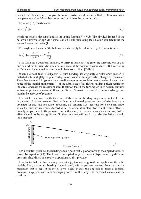
III. ModellingFEM <strong>modelling</strong> <strong>of</strong> a <strong>bellows</strong> <strong>and</strong> a <strong>bellows</strong>-<strong>based</strong> <strong>micromanipulator</strong>desired, but they just need to give the same constant result when multiplied. It means that anew parameter Q = E·I can be chosen, <strong>and</strong> put it into the beam formula.Equation (3.6) thus becomes:3QF = ⋅δxl 3(3.7)which has exactly the same kind as the spring formula F = k·δx. The physical length l <strong>of</strong> the<strong>bellows</strong> is known, so applying some load on it <strong>and</strong> simulating the situation can determine thelone unknown parameter Q.The angle α at the end <strong>of</strong> the <strong>bellows</strong> can also easily be calculated by the beam formula:22F ⋅lltan( α ) = − = −F⋅(3.8)2⋅E ⋅ I 2QThis furnishes a good confirmation, to verify if formula (3.8) gives the same angle α as thatone ensued by the simulation, taking into account the computed parameter Q. But accordingto Calladine, the internal pressure should have some effect [Call83].When a curved tube is subjected to pure bending, its originally circular cross-section isdistorted into a slightly elliptic configuration, without an appreciable change <strong>of</strong> perimeter.Therefore there will in general be a small change in the enclosed cross-sectional area – <strong>and</strong>hence <strong>of</strong> the inertial momentum I – <strong>of</strong> the tube, since <strong>of</strong> all figures having a given perimeter,the circle encloses the maximum area. It follows that if the tube which is to be bent sustainsan interior pressure, the overall flexure stiffness <strong>of</strong> it must be expected to be somewhat greaterthan in the absence <strong>of</strong> pressure.It is not known how exactly the curve <strong>of</strong> the function bending vs pressure looks like, buttwo certain facts are known. First, without any internal pressure, one definite bending isobtained for each applied force. Secondly, the bending must decrease for a constant force,when the pressure increases. According to Calladine, it is clear that this stiffening effect isdirectly proportional to the pressure. But in this case, the pressure changes are so tiny, that itseffect should not be so significant. So the curve that will result from the simulations shouldlook like that :δx 0Bending [mm]Full-range working region0Pressure [mN/mm 2 ]For a constant pressure, the bending should be directly proportional to the applied force, asshown by equation (3.7). The force to be applied to get a constant displacement by differentpressures should also be directly proportional to that pressure.In order to find out this bending parameter Q, time-varying loads are applied on the solidmodels. First, a constant bending force is used, with a pressure varying from zero to themaximum that is applied in the <strong>bellows</strong>. Then, exactly the opposite is done: a constantpressure is applied with a time-varying force. In this way, the expected curves can beconfirmed.∞26