fem modelling of a bellows and a bellows- based micromanipulator
fem modelling of a bellows and a bellows- based micromanipulator
fem modelling of a bellows and a bellows- based micromanipulator

You also want an ePaper? Increase the reach of your titles
YUMPU automatically turns print PDFs into web optimized ePapers that Google loves.
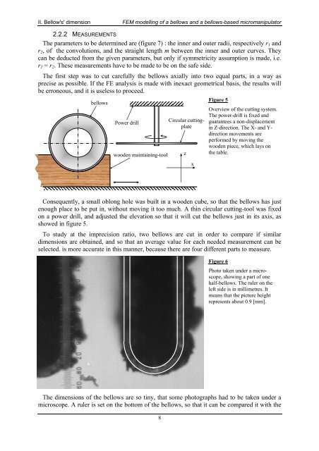
II. Bellow's' dimensionFEM <strong>modelling</strong> <strong>of</strong> a <strong>bellows</strong> <strong>and</strong> a <strong>bellows</strong>-<strong>based</strong> <strong>micromanipulator</strong>2.2.2 MEASUREMENTSThe parameters to be determined are (figure 7) : the inner <strong>and</strong> outer radii, respectively r 1 <strong>and</strong>r 2 , <strong>of</strong> the convolutions, <strong>and</strong> the straight length m between the inner <strong>and</strong> outer curves. Theycan be deducted from the given parameters, but only if symmetricity assumption is made, i.e.r 1 = r 2 . These measurements have to be made to be on the safe side.The first step was to cut carefully the <strong>bellows</strong> axially into two equal parts, in a way asprecise as possible. If the FE analysis is made with inexact geometrical basis, the results willbe erroneous, <strong>and</strong> it is useless to proceed.<strong>bellows</strong>Power drillwooden maintaining-toolCircular cuttingplatezxFigure 5Overview <strong>of</strong> the cutting system.The power-drill is fixed <strong>and</strong>guarantees a non-displacementin Z-direction. The X- <strong>and</strong> Y-direction movements areperformed by moving thewooden piece, which lays onthe table.Consequently, a small oblong hole was built in a wooden cube, so that the <strong>bellows</strong> has justenough place to be put in, without moving it too much. A thin circular cutting-tool was fixedon a power drill, <strong>and</strong> adjusted the elevation so that it will cut the <strong>bellows</strong> just in its axis, asshowed in figure 5.To study at the imprecision ratio, two <strong>bellows</strong> are cut in order to compare if similardimensions are obtained, <strong>and</strong> so that an average value for each needed measurement can beselected. is more accurate in this manner, because there are four different parts to measure.Figure 6Photo taken under a microscope,showing a part <strong>of</strong> onehalf-<strong>bellows</strong>. The ruler on theleft side is in millimetres. Itmeans that the picture heightrepresents about 0.9 [mm].The dimensions <strong>of</strong> the <strong>bellows</strong> are so tiny, that some photographs had to be taken under amicroscope. A ruler is set on the bottom <strong>of</strong> the <strong>bellows</strong>, so that it can be compared it with the8