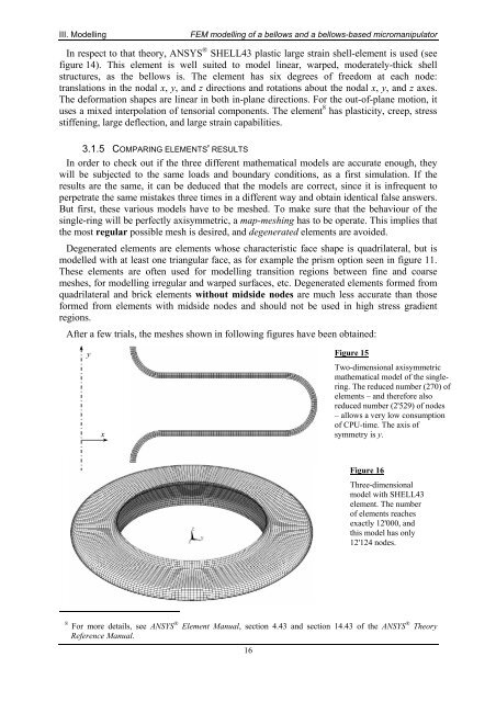
FEM <strong>modelling</strong> <strong>of</strong> a <strong>bellows</strong> <strong>and</strong> a <strong>bellows</strong>-<strong>based</strong> <strong>micromanipulator</strong>III. Modellingstrain concentration at those nodes. Even substantial strain-gaps would appear between somenodes, so that the result would then be less accurate, or maybe wrong. Hence, to avoid theseproblems <strong>and</strong> to make the aspect ratio <strong>of</strong> the elements close to 1, meshing has to be very fine.As shown in next figure, the number <strong>of</strong> elements will become enormous.(a)(b)Figure 13Mesh (a) is too coarse <strong>and</strong> couldinduce errors. So the mathematicalmodel should be more accurate,corresponding to the mesh (b).3.1.4 CHOOSING RIGHT SHELL 3D-ELEMENTBecause <strong>of</strong> the thin walls, this <strong>bellows</strong> should properly be classed as a shell <strong>of</strong> revolution forstress <strong>and</strong> displacement analyse purpose. The geometry <strong>of</strong> a shell is defined by its thickness<strong>and</strong> its midsurface, which is a curved surface in space. Load is carried by a combination <strong>of</strong>membrane action <strong>and</strong> bending action. A thin shell can be very strong if membrane actiondominates, in the same way that a wire can carry great load in tension but only small load inbending. A shell <strong>of</strong> a given shape can carry a variety <strong>of</strong> distributed loadings by membraneaction alone.However, no shell is completely free <strong>of</strong> bending stresses. They appear at or near point loads,line loads, reinforcements, junctures, changes <strong>of</strong> curvature <strong>and</strong> supports. In short, anyconcentration <strong>of</strong> load or geometric discontinuity can be expected to produce bending stresses,<strong>of</strong>ten much larger than membrane stresses, but usually quite localised in a “boundary layer”near the load or discontinuity.Flexure stress <strong>and</strong> bending moment in a shell are related in the same way as for a plate:t / 2Mx= ∫σ x⋅ z ⋅ dz ,y= ∫−t/ 2t / 2M σy⋅ z ⋅ dz , Mxy= ∫τ xy⋅ z ⋅ dz(3.3)−t/ 2where t is the given thickness <strong>of</strong> the shell element.A quadrilateral shell element can be produced by combining quadrilateral plane <strong>and</strong> plateelement. A four-node “flat” quadrilateral is in general a warped element because its nodes arenot all coplanar. A modest amount <strong>of</strong> warping can seriously degrade the performance <strong>of</strong> anelement. Commercial s<strong>of</strong>tware may allow only a very small amount <strong>of</strong> deformations.Curved elements <strong>based</strong> on shell theory avoid some shortcomings <strong>of</strong> flat elements, butintroduce other difficulties. More data are needed to describe the geometry <strong>of</strong> a curvedelement. Formulation is complicated, as it invokes a shell theory – <strong>of</strong> which there are many.Membrane <strong>and</strong> bending actions are coupled within the element, so it is harder to avoidmembrane locking, that is, harder to avoid great overstiffness in bending because details <strong>of</strong>the element formulation cause membrane strains to appear in association with bending action,<strong>and</strong> membrane stiffness is far greater than bending stiffness if the shell is thin.t / 2−t/ 2±I®L−¬°JXK¯ZYFigure 14Explanation picture <strong>of</strong> the SHELL43 element. It ismade <strong>of</strong> four nodes, I, J, K <strong>and</strong> L, <strong>and</strong> six differentfaces. Each <strong>of</strong> these surfaces can admit loads. At eachnode a different thickness t can be defined. Thiselement has plasticity, creep, stress stiffening, largedeflection <strong>and</strong> strain capabilities.15
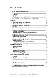
III. ModellingFEM <strong>modelling</strong> <strong>of</strong> a <strong>bellows</strong> <strong>and</strong> a <strong>bellows</strong>-<strong>based</strong> <strong>micromanipulator</strong>In respect to that theory, ANSYS ® SHELL43 plastic large strain shell-element is used (seefigure 14). This element is well suited to model linear, warped, moderately-thick shellstructures, as the <strong>bellows</strong> is. The element has six degrees <strong>of</strong> freedom at each node:translations in the nodal x, y, <strong>and</strong> z directions <strong>and</strong> rotations about the nodal x, y, <strong>and</strong> z axes.The deformation shapes are linear in both in-plane directions. For the out-<strong>of</strong>-plane motion, ituses a mixed interpolation <strong>of</strong> tensorial components. The element 8 has plasticity, creep, stressstiffening, large deflection, <strong>and</strong> large strain capabilities.3.1.5 COMPARING ELEMENTS' RESULTSIn order to check out if the three different mathematical models are accurate enough, theywill be subjected to the same loads <strong>and</strong> boundary conditions, as a first simulation. If theresults are the same, it can be deduced that the models are correct, since it is infrequent toperpetrate the same mistakes three times in a different way <strong>and</strong> obtain identical false answers.But first, these various models have to be meshed. To make sure that the behaviour <strong>of</strong> thesingle-ring will be perfectly axisymmetric, a map-meshing has to be operate. This implies thatthe most regular possible mesh is desired, <strong>and</strong> degenerated elements are avoided.Degenerated elements are elements whose characteristic face shape is quadrilateral, but ismodelled with at least one triangular face, as for example the prism option seen in figure 11.These elements are <strong>of</strong>ten used for <strong>modelling</strong> transition regions between fine <strong>and</strong> coarsemeshes, for <strong>modelling</strong> irregular <strong>and</strong> warped surfaces, etc. Degenerated elements formed fromquadrilateral <strong>and</strong> brick elements without midside nodes are much less accurate than thoseformed from elements with midside nodes <strong>and</strong> should not be used in high stress gradientregions.After a few trials, the meshes shown in following figures have been obtained:yxFigure 15Two-dimensional axisymmetricmathematical model <strong>of</strong> the singlering.The reduced number (270) <strong>of</strong>elements – <strong>and</strong> therefore alsoreduced number (2'529) <strong>of</strong> nodes– allows a very low consumption<strong>of</strong> CPU-time. The axis <strong>of</strong>symmetry is y.Figure 16Three-dimensionalmodel with SHELL43element. The number<strong>of</strong> elements reachesexactly 12'000, <strong>and</strong>this model has only12'124 nodes.8 For more details, see ANSYS ® Element Manual, section 4.43 <strong>and</strong> section 14.43 <strong>of</strong> the ANSYS ® TheoryReference Manual.16