fem modelling of a bellows and a bellows- based micromanipulator
fem modelling of a bellows and a bellows- based micromanipulator
fem modelling of a bellows and a bellows- based micromanipulator

Create successful ePaper yourself
Turn your PDF publications into a flip-book with our unique Google optimized e-Paper software.
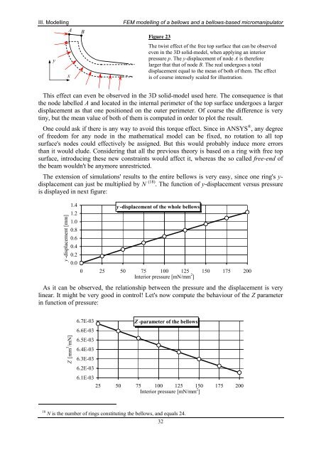
III. ModellingABFEM <strong>modelling</strong> <strong>of</strong> a <strong>bellows</strong> <strong>and</strong> a <strong>bellows</strong>-<strong>based</strong> <strong>micromanipulator</strong>Figure 23yxThe twist effect <strong>of</strong> the free top surface that can be observedeven in the 3D solid-model, when applying an interiorpressure p. The y-displacement <strong>of</strong> node A is thereforelarger that that <strong>of</strong> node B. The real undergoes a totaldisplacement equal to the mean <strong>of</strong> both <strong>of</strong> them. The effectis <strong>of</strong> course intensely scaled for illustration.This effect can even be observed in the 3D solid-model used here. The consequence is thatthe node labelled A <strong>and</strong> located in the internal perimeter <strong>of</strong> the top surface undergoes a largerdisplacement as that one positioned on the outer perimeter. Of course the difference is verytiny, but the mean value <strong>of</strong> both <strong>of</strong> them is computed in order to plot the result.One could ask if there is any way to avoid this torque effect. Since in ANSYS ® , any degree<strong>of</strong> freedom for any node in the mathematical model can be fixed, no rotation to all topsurface's nodes could effectively be assigned. But this would probably induce more errorsthan it would elude. Considering that all the previous theory is <strong>based</strong> on a ring with free topsurface, introducing these new constraints would affect it, whereas the so called free-end <strong>of</strong>the beam wouldn't be anymore unrestricted.The extension <strong>of</strong> simulations' results to the entire <strong>bellows</strong> is very easy, since one ring's y-displacement can just be multiplied by N (18) . The function <strong>of</strong> y-displacement versus pressureis displayed in next figure:y -displacement [mm]1.41.21.00.80.60.40.20.0y -displacement <strong>of</strong> the whole <strong>bellows</strong>0 25 50 75 100 125 150 175 200Interior pressure [mN/mm 2 ]As it can be observed, the relationship between the pressure <strong>and</strong> the displacement is verylinear. It might be very good in control! Let's now compute the behaviour <strong>of</strong> the Z parameterin function <strong>of</strong> pressure:6.7E-03Z -parameter <strong>of</strong> the <strong>bellows</strong>6.6E-03Z [mm 3 /mN]6.5E-036.4E-036.3E-036.2E-036.1E-0325 50 75 100 125 150 175 200Interior pressure [mN/mm 2 ]18 N is the number <strong>of</strong> rings constituting the <strong>bellows</strong>, <strong>and</strong> equals 24.32