MiniSteam Instruction Manual - HygroMatik
MiniSteam Instruction Manual - HygroMatik
MiniSteam Instruction Manual - HygroMatik

You also want an ePaper? Increase the reach of your titles
YUMPU automatically turns print PDFs into web optimized ePapers that Google loves.
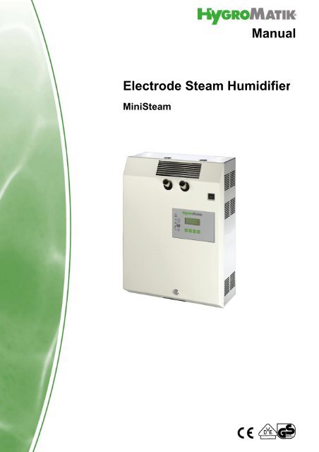
<strong>Manual</strong>Electrode Steam Humidifier<strong>MiniSteam</strong>
A Word about Water QualityThe mode of operation of all electrode steam humidifiers is based on the fact that water containsminerals and is therefore conductive.• "normal" tap water is ideal.• but what is "normal" tap water exactly?Users of <strong>HygroMatik</strong> units in the most diverse areas consider their tap water "normal."<strong>HygroMatik</strong> typically defines "normal" as feed water with a conductivity between 200 and 500 µS/cm (microSiemens per centimeter) at 15° C.Some areas, however, are supplied with tap water whose quality is outside the parameters specifiedby <strong>HygroMatik</strong>. If the <strong>HygroMatik</strong> steam humidifier's control is not adjusted correctly in theseareas, the unit cannot perform optimally. For example, the electrodes could wear out particularlyquickly or the steam production could be too low.The operational parameters set by <strong>HygroMatik</strong> in the factory are intended for normal tap water.However, they can very easily be reprogrammed to fit the special requirements of a particulararea. In addition, it is possible to install a plastic star in the cylinder in order to increase the lifespan of the electrodes or to provide a flushing mechanism to extend maintenance intervals.Because of this you should monitor your new unit during initial operation. Make sure that it hasbeen properly installed and is operating to your satisfaction.Consult your <strong>HygroMatik</strong> specialists. We will test the quality of your water and advise you oninstallation and initial operation. Your <strong>HygroMatik</strong> steam humidifier will be carefully adapted toyour particular application. Copyright <strong>HygroMatik</strong> GmbH; <strong>MiniSteam</strong>, July 2012Information in this manual is subject to change or alteration without prior notice.Current version of this manual can be found at: www.hygromatik.co.ukWarning, Hazardous Voltage: All work to be performed by trained personnel only.All electrical installation and servicing of the electrical components of this unit to beperformed by qualified electricians only. Disconnect power supply before installationand servicing!Page 2
1. Introduction ....................................................................................................................... 51.1 Directions for Use .............................................................................................................. 51.2 Typographic Distinctions ...................................................................................................61.3 Documentation .................................................................................................................. 62. Safety Notes ....................................................................................................................... 72.1 Overview ........................................................................................................................... 72.2 Guidelines for Safe Operation ........................................................................................... 72.3 Disposal after Dismantling .................................................................................................83. Transport ............................................................................................................................ 93.1 Overview ........................................................................................................................... 93.2 Carton outer Size and Weight ........................................................................................... 93.3 Packing .............................................................................................................................. 103.4 Interim Storage .................................................................................................................. 103.5 Check for Complete and Correct Delivery of Goods ......................................................... 103.6 Included in the Delivery ..................................................................................................... 104. Operation and Installation ................................................................................................ 114.1 Mode of Operation ............................................................................................................. 114.2 Installation and Operation .................................................................................................115. Installation ......................................................................................................................... 155.1 Steam Humidifier Operating Environment ......................................................................... 155.1.1 Fitting measures ............................................................................................................. 165.2 Unit Installation Check ....................................................................................................... 175.3 Unit Dimensions ................................................................................................................ 186. Water Installation .............................................................................................................. 196.1 Operation with Softened Water ......................................................................................... 196.2 Water Supply ..................................................................................................................... 206.3 Water discharge ................................................................................................................ 216.4 Water Installation Check ...................................................................................................227. Electrical Connection ........................................................................................................ 237.1 Electrical Installation .......................................................................................................... 237.2 Cable Connections ............................................................................................................ 257.3 Safety Interlock .................................................................................................................. 267.4 Wiring Diagram .................................................................................................................. 267.5 Electrical Installation Checklist ..........................................................................................268. Maintenance ....................................................................................................................... 278.1 Maintenance Work ............................................................................................................ 288.2 Access Electrical Enclosure .............................................................................................. 288.3 Removing and Cleaning the Steam Cylinder .................................................................... 308.4 Electrode wear .................................................................................................................. 338.4.1 Original Electrode Lengths ............................................................................................. 338.4.2 Uneven Electrode Lengths ............................................................................................. 348.5 Replacing Electrodes ........................................................................................................ 348.6 Cleaning the Blow- Down Pump ........................................................................................ 36Page 3
8.7 Cleaning the Water Inlet Solenoid Valve ........................................................................... 368.8 Chekking Cable Connections and Electrode Cables ......................................................... 378.9 Checking Operation ........................................................................................................... 378.10 Dismantling ...................................................................................................................... 379. Commissioning ................................................................................................................. 3810. EC-Declaration of Conformity ........................................................................................ 3911. Spare Parts ...................................................................................................................... 4012. Fax Form - Order for spare parts ................................................................................... 4213. Technical Data ................................................................................................................. 4314. Exploded View ................................................................................................................. 4415. View of housing ............................................................................................................... 45Page 4
1. IntroductionDear Customer,Thank you for choosing a <strong>HygroMatik</strong> steam humidifier.<strong>HygroMatik</strong> steam humidifiers represent the latest in humidificationtechnology.They will impress you with their safety, ease of use and economicaloperation.In order to operate your <strong>HygroMatik</strong> steam humidifier safely,properly and efficiently, please read these operating instructions.Employ your steam humidifier only in sound condition and asdirected. Consider potential hazards and safety issues and followall the recommendations in these instructions.If you have additional questions, please contact us:Tel.: +49-(0)4193 / 895-0 (Main Number)Tel.: +49-(0)4193 / 895-293 (Technical Support Hotline)Fax: +49-(0)4193 / 895-33e-mail: hot1@<strong>HygroMatik</strong>.deFor all technical questions or spare parts orders, please be preparedto provide unit type and serial number (see name plate onthe unit).1.1 Directions for UseThe <strong>HygroMatik</strong> steam humidifier is intended for steam production.Proper usage also entails following <strong>HygroMatik</strong>'s instructions forinstallation, dismantling, reassembly, initial operation and operationand maintenance, as well as disposal procedures.Only qualified, authorized personnel may operate or service theunit. Workers who transport or service the unit must have readand understood the relevant sections of the operating instructions,especially the section "Safety Notes." In addition, staffmust receive safety training about potential hazards from theoperator. Place a copy of the operating instructions at the locationwhere the unit is operated.Page 5
Use feed water with a conductivity between 125 and 1250 µS/cm onlyD1: Lower thresholdC1: Range of reduced conductivityA: Normal tap waterB: Range of heightened conductivityC2: Range of heigh conductivityD2: Upper thresholdWarning: <strong>HygroMatik</strong> steam humidifiers emit steam with a temperatureof 100° C. The steam may not be inhaled directly.The <strong>HygroMatik</strong> Steam Humidifier is not designed for outdoor fitting.1.2 Typographic Distinctions preceded by a bullet: general specifications.» preceded by an arrow: Procedures for servicing ormaintenance which should or must be performed in theindicated order. Installation step which must be checked off.italics Terms used with graphics or drawings.1.3 DocumentationRetentionPlease retain these operating instructions in a secure, alwaysaccessible location. If the product is resold, turn the documentationover to the new operator. If the documentation is lost, pleasecontact <strong>HygroMatik</strong>.Versions in Other LanguagesThese operating instructions are available in several languages.If interested, please contact <strong>HygroMatik</strong> or your <strong>HygroMatik</strong>dealer.Page 6
2. Safety Notes2.1 OverviewThese safety notes are required by law. They promote workplacesafety and accident prevention.Warnings and Safety SymbolsThe safety symbols below identify sections containing warningsabout hazards or potential dangers. Please familiarize yourselfwith these symbols.Warning: Failure to observe this warning may result in seriousinjury or death and/or damage to the unit.Danger, Hazardous Voltage: Hazardous electrical current!Failure to observe this warning may result in injury or even seriousinjury or death.Warning: Failure to follow these instructions may result in damageto the unit due to electrostatic discharge. The electroniccomponents of the humidifier control are very sensitive to electrostaticdischarges. In order to safeguard these componentsduring installation and servicing, steps must be taken to protectagainst ESD.Reminder: Materials and consumables must be handled and/ordisposed of as required by law.Note: Appears before explanations or cross-references whichrefer to other sections of the operating instructions.2.2 Guidelines for Safe OperationOverviewObey all safety notes and warnings present on the unit. In caseof a malfunction, switch off the unit immediately and prevent arestart. Repair malfunctions promptly. After any repair work,have qualified personnel check the safe operation of the unit.Use original spare parts only. Additional national safety regulationsalso fully apply to the operation of this unit.This unit is not designed for the use by persons (also children)with limited physical, sensory and mental abilities - or withoutknowledge and experience. Unless they are supervised or trainedby a person, who is responsible for their safety.Supervise children in order to ensure that they will not play withthe unit.The unit is only allowed to work with connected steam hose thatPage 7
safely leads the steam.<strong>HygroMatik</strong> steam humidifiers are IP20-protected. Make surethat the unit is protected from drips in its installed location.Installing a humidifier in a room without water discharge requiressafety devices to protect against water leakages.Accident Prevention RegulationsComply with the Accident Prevention Regulation Electrical Systemsand Equipment to prevent injury to yourself and others.Operation of the Unit:Do not perform any work which compromises the safety of theunit. Regularly check that all safety and monitoring devices arefunctioning normally. Do not remove or disable safety devices.Installation, Dismantling, Maintenance and Repair of theUnit:Disconnect unit components from power supply prior to maintenanceor repair work.Attaching or installing additional components is permitted onlywith the written consent of the manufacturer.ElectricalWork on the electrical system must be performed by qualifiedpersonnel.Disconnect unit components from power supply prior to work.It is not allowed to connect the unit to DC voltage supply.In case of a malfunction in the electrical power supply, switch offthe unit immediately. Use only original fuses with the appropriateamperage rating. Regularly check the unit's electrical equipment.Promptly repair any damage, such as loose connections,burned wiring or defective electrical insulation. After proper electricalinstallation or repair, test all safety mechanisms (such asgrounding resistance).2.3 Disposal after DismantlingNote: The operator is responsible for the disposal of unit componentsas required by law.Page 8
3. Transport3.1 OverviewNote: Proceed carefully when transporting the steam humidifierin order to prevent damage due to stress or careless loading andunloading.3.2 Carton outer Size and WeightHyLine:Type*CompactLine:<strong>MiniSteam</strong>:Height[cm]Width[cm]Depth[cm]* Dimensions and weights may vary slightly.Weight[kg]HY05- 08 58 56 32 16HY13- 17 75 63 37 24HY23 75 63 37 25HY30 81 67 41 33HY45 88 76 48 46HY60 80 104 41 54HY90- 116 90 117 48 77Type* Height [cm] Width [cm] Depth [cm] Weight [kg]C01 46 45 26 11C02 48 44 31 12C06 52 50 28 13C10 58 51 31 14C17 75 54 37 22C22 75 54 37 22C30 75 58 37 23C45 81 63 41 25C58 90 72 48 36Type* Height [cm] Width [cm] Depth [cm] Weight[kg]*MS 5 59 48 28 13MS 10 68 51 31 15Page 9
3.3 PackingNote: Notice the symbols affixed to the packing box.3.4 Interim StorageStore the unit in a dry place and protect from frost.3.5 Check for Complete and Correct Delivery ofGoodsUpon receipt of the unit, confirm that:the type and serial number on the name plate matchthose specified in the order and delivery documentsandthe equipment is complete and all parts are in perfectconditionNote: In case of damage during shipment or missing parts,immediately notify the carrier or supplier in writing.Time limits for filing freight claims with shipping companies are*:Shipping CompaniesMailRailTruck and Rail CarriersParcel ServiceAfter Receipt of Goodsno later than 24 hoursno later than 7 daysno later than 4 daysimmediately* Time limits for some services subject to change.3.6 Included in the DeliveryThe delivery includes: Unit of the selected humidifier type including selectedcontrol. Water installation hose 0,6m, 3/4".Mounting set with anchors and screws. For HyLinetypes HY45 to HY116, extra mounting bar.Operating <strong>Instruction</strong>s for the unit and the control.Ordered accessories (steam manifold, steam hose,condensate hose, etc.).Maintenance o-ring set for steam cylinder.Page 10
4. Operation and Installation4.1 Mode of OperationThe <strong>HygroMatik</strong> steam humidifier utilizes the conductivity normallypresent in tap water for steam production. Electrodesinside an enclosed steam cylinder are immersed directly into thetap water. They are connected to the alternating current.The conductivity of the water generates an electric currentbetween the electrodes. In this way, the electric power suppliedis converted directly into heat without energy loss.The amperage is a function of the available voltage, theimmersed electrode surface area, the average distance betweenthe electrodes and the water conductivity. The steam output ofthe humidifier is determined by electric power usage, which isregulated by increasing or decreasing the immersed surfacearea of the electrodes.Concurrently, a self-regulating control keeps conductivity withina specified range.The steam produced has a temperature of about 100°C withminimal excess pressure ("pressureless steam"). It is largelyfree of minerals and germ-free. Mineral deposits typically remainbehind in the cylinder.4.2 Installation and OperationWhen the controller specifies an increase in humidity, the maincontactor is switched on and the electrodes (48) are suppliedwith power. The water inlet solenoid valve (25) feeds water intothe steam cylinder (16+19).As soon as the electrodes are immersed, the current begins toflow. The water is now heated. When the pre-selected output isreached, the control turns off the solenoid valve and interruptsthe water supply.After a short heating up period, the water between the electrodesbegins to boil and vaporize. The vaporization lowers thewater level (W) in the steam cylinder, reducing the output provided.The inlet solenoid valve, equipped with a fine mesh filter,intermittently admits fresh water.Humidifier power usage is continuously monitored. With a coldstart-up, the nominal current increases to 125% in order toachieve quick-start output parameters. This activates the electronicoverflow limiter which causes a partial draining of the cylinder.This reduces the immersed surface area of the electrodes,lowering power usage.Page 11
2214828641112381014151622211758223926492220222422222218193530313242434425Please also see Section „Exploded View“.37Location Designation1 steam nozzle6 vent pipe10 max. water level sensor electrode14 water drain, discharge16 top part of steam cylinder17 o-ring cylinder flange18 cylinder flange and o-ring19 lower part of cylinder25 solenoid valve water inlet32 blow-down pump35 o-ring37 cylinder base48 electrodesPage 12
The concentration of dissolved salts increases over time, whichcan lead to a rise in the conductivity of the water. If this continues,conductivity may increase until a short circuit occurs. Thiscould damage the unit, but in any case would significantlyreduce the life span of the electrodes.For this reason, regular, periodic blow-downs of some of theconcentrated water are very important. Following this procedureas recommended provides stable cylinder water conductivity aswell as minimal water loss for the expected service life of the cylinder.Water blow-down is performed by a blow-down pump (32). Thefunctioning of the blow-down pump is continuously monitoredduring operation. If the pump is damaged, the steam humidifiershuts down.With normal water quality, the blow-down loss rate is between7% and 15% of the amount of steam produced. The steam cylinderrequires complete drainage every 3-8 days, regardless ofthe water quality.Mineral deposits settle in the open area below the electrodesand are removed through periodic maintenance. The blow-downpump itself has wide openings and can flush out smaller piecesof mineral deposit. This extends the service life of the unit andreduces the required maintenance interval.During blow-downs, water flows from the pump into the drainagesystem.A sensor electrode (10) monitors the maximum water capacityof the cylinder. When the water level reaches the sensor electrode,the water supply is interrupted. This can occur when thewater has low conductivity or when the electrodes are worn out.In the case of low water conductivity, however, this state usuallylasts only a short time. The built-in control and the large areaelectrodes combine to produce a rapid rise in conductivity byincreasing the concentration of the water.Page 13
The steam cylinder consists of a top (16) and lower (19) partjoined with a cylinder flange. The seal between the cylinder andcylinder base (37), as well as between the top and lower part ofthe cylinder, is maintained using an o-ring (35).Warning:During operation and also soon afterwards the steamnozzle is hot! If touched this can cause burns to theskin.During operation the cross-flow fan rotates. Do nottouch the fan during operation.During operation hot steam discharges from the nozzle.In the field of the visible steam cloud contact can causeburns to the skin.Due to pollution or incorrect installation hot water coulddischarge from the nozzle.Page 14
5. InstallationWarning: Installation of this unit to be attempted only by qualifiedpersonnel. We accept no liability for damage due to faultyinstallation.Obey all safety notes and warnings present on the unit.During installation the unit must be disconnected from its powersupply.Attaching or installing additional components is permitted onlywith the written consent of the manufacturer, or else the warrantyis void.5.1 Steam Humidifier Operating EnvironmentNote: When selecting the installation site for the steam humidifier,note that: Ambient temperature must be between 5° and 40° C. Relative humidity must not exceed 80% RH. The minimum clearances indicated in the diagrambelow must be observed; these are necessary toensure adequate ventilation for the housing. The rear panel of the steam humidifier heats up duringoperation (to a maximum of 60°C). Take care that theconstruction on which the unit is mounted is not madeof temperature-sensitive material. Place the steam humidifier so that the unit is easilyaccessible with sufficient space to perform maintenance. Make sure that there are no people and bearing materialsbelow the steam cloud (approx. 3 meters in exhaustdirection). The steam humidifier is not qualified for exterior applications.Page 15
5.1.1 Fitting measuresWall Distances [mm]> 150Page 16
Wall MountingNote: The steam humidifier must be installed vertically in orderto function properly.Note: The steam humidifier should be positioned such thatdraught effects are avoided. The minimum height is 0.15 mabove floor level but we propose a height of 2m in order to avoidscalding.Warning: If the installation of this unit is attempted by only oneperson there is a risk that the unit drops down. We propose tocarry out the installation by two persons.» Position the steam humidifier in the planned location,adjust with spirit level and mark position of hangingbolts. See also "Equipment Dimensions".» Hang the unit onto bolts screwed into the marked position.5.2 Unit Installation CheckAttention: This unit may only be operated by qualified and properlytrained personnel.Please check the installation using the following list:Does unit hang vertically?Are wall distances to the unit within the rangeIs the unit installed in such a way that draught effectsare avoided?Are all bolts and clamps tightened?Page 17
5.3 Unit DimensionsPage 18
6. Water InstallationWarning: When installing the water installation, note the following: Have all work performed by a professional. Disconnect power supply before installation. Obey local public utility regulationsVerify that necessary safety measures have been taken– in compliance with either German Technical and ScientificAssociation for Gas and Water (DVGW) guidelines(DIN EN1717) or local regulations – to eliminatebackflow of polluted water into drinking water treatmentfacilities. This can mean installing a backflow preventer.Within the humidifier, a double check valve (58) islocated in the water supply line. It prevents - in accordancewith DIN EN 61770 - the backflow of water. Use feed water without chemical additives and with aconductivity between 200 and 800 µS/cm only. Aboveconductivity levels of 800µS/cm to a maximum of1250µS/cm and below conductivity levels of 200µS/cmto a minimum of 125µS/cm, special adjustments arerequired. In this case please contact <strong>HygroMatik</strong>. The water supply temperature may not exceed 40° C. Water installation pressure: 1 - 10 bar (100 x 10 3 to 100x 10 4 pascal). Blow-down water must be able to drain. For water installation please use the water connectinghose that is delivered with the unit.6.1 Operation with Softened WaterWarning: Unless special measures are taken, feeding softenedwater into the <strong>HygroMatik</strong> steam humidifier is dangerous. It cancause unacceptably high conductivity the formation of salt bridges between the electrodesand the electrode leads on the inner surface of the toppart of the steam cylinder foaming in the steam cylinderSalt bridges cause electrical arcs. These are indicated by thepresence of black grooves in the top part of the cylinder. The toppart must be replaced to prevent further damage to the cylindermaterial, as well as short circuits which trip main circuit breakers.Foam comes into contact with the maximum water level sensorelectrode and triggers a signal indicating the cylinder is filled tocapacity, even though this is false and the nominal current hasnot yet been reached.Page 19
Note: Please contact <strong>HygroMatik</strong> if you wish to operate the unitwith softened water.If using a water softening system, we recommend diluting thesoftened water with normal tap water to produce an overall hardnessbetween 4-8°dH. This value can be set lower if the waterdoes not foam.When blending softened water with deionized water (conductivity= 5-20 µS / cm) it is to ensure that the mixture neither foamsnor is too low in conductivity.When feed water contains softened water, the level of conductivityis typically higher at operating temperature. Install a Hygro-Matik "cylinder star" to extend the service life of the electrodes.6.2 Water Supply» Install a shut-off valve (SV) in the supply line.» Install a water filter (WF) if water quality requires it.Note: Shut-off valve (SV) and water filter (WF) are not suppliedwith the unit» <strong>HygroMatik</strong> provides a water hose (56) with a cap nut atboth ends which can be used for water installation.Install as follows:» Screw and tighten the cap nut with its inner seal ringaround the water supply screw connection that protrudesfrom the base.Note: Tightening too much will destroy the fitting. The valvestrainer must be placed inside the solenoid valve.Page 20
» Use a cap nut (internal thread ¾“) with inner seal for acustomer-provided water installation.6.3 Water dischargemin.: 250mmmax.: 1000mmWarning: During blow down hot water with a temperature ofabout 95°C is being drained. If touched this can cause burns tothe skin.Warning: Pay attention for free and non-pressure drainage ofthe water! During blow down up to 0,3 L/sec are being drained.For water discharge, we recommend installation of a flexiblewater drain hose. Humidifier and wastewater discharge must beon the same pressure level.Please note:Do not bend the drain hose.Install discharge line and drain pipe made from temperatureresistant material (to 95° C).Install water discharge as followsLoosely insert a length of 1 1/4 " drain hose, approx.250 - 1000 mm, into a drain pipe with a minimum innerdiameter of 40 mm and seal with a rubber gasket. Fit water drain hose over the pump drain hose and fastento the housing drain connection.A grounding clip is fixed on the inner surface of the housingdrain connection. The end of the pump drain hose is pushed intothis clip. During blow-down, the grounding clip is in direct contactwith the water and shunts potential residual electric currentsaway from the housing.Page 21
There is a 3mm-wide crack between the pump drain hose jacketand the inner surface of the housing drain connection. If watercollects in the base plate, it will flow through this crack into thedrainage system.6.4 Water Installation CheckGo down the following water installation checklist:Are all screws and clamps properly tightened?Is the water supply pipe flushed?Was the water installation correctly installed?Can the blow-down water drain freely?Was the water discharge correctly installed?Is there no leakage from the water supply pipe andwater discharge?Warning: Flush the water supply pipe before connecting to thesolenoid valve, especially a newly installed pipe. This preventspremature damage.Page 22
7. Electrical ConnectionDanger, Hazardous Voltage: All work related to electrical installationto be performed by authorized personnel only (electriciansor professionals with equivalent training). The customer isresponsible for checking qualifications.Danger, Hazardous Voltage: Do not plug the steam humidifierinto the power grid until after all installation work has been completed.Warning: The electronic components of the humidifier controlare very sensitive to electrostatic discharges. In order to protectthese components during any type of installation, steps must betaken to guard against damage from electrostatic discharge(ESD protection).Warning: For electrical installation, note the following:Disconnect power supply before installation and protectagainst restart.Verify the absence of electric current.Make sure the unit is switched off before installing orremoving the display plate or basic PCB.Professionally lay electrical connector cable.Install the electrical connections according to the wiringdiagram.For units with rated power over 33 kW, only a permanentconnection to a permanent wire is allowable (GermanAssociation for Electrical, Electronic & InformationTechnologies [VDE] Standard 0700 Section 98).Verify that all terminals have been tightened.7.1 Electrical Installation» Fuses must have a contact gap of at least 3mm perpole.» Install a separate main connection for each steam cylinder,complete with main contactor, main switch, etc.» Connect potential equalization to the outer ground bolt.» Observe the German Association for Electrical, Electronic& Information Technologies [VDE] Standard 0100when selecting a connection cross section.» Install main power supplies as follows:Page 23
Type Standard Main Power SupplyHY05 - HY451 x 400V/3Phase/NHY60 - HY116 2 x 400V/3Phase/NC01, C02 1 x 230/1Phase/NC06 - C581 x 400V/3Phase/NMS5, MS101 x 400V/3Phase/NMS51 x 230/1Phase/NDBE 21 x 230V/1PhaseDBE 6-451 x 400V/3Phase/NOther voltages are available on request.We recommend employing medium blow main fuses (applicableonly to the grid voltages above). See table below indicating maximumpower usage for each circuit protection:When using fault current circuit breakers please use a separateone for the humidifier.HyLine:Type Power Usage Circuit ProtectionHY05 5,4 A 3 x 6AHY08 8,7 A 3 x 10AHY13 14,1 A 3 x 16 AHY17 18,4 A 3 x 20 AHY23 24,9 A 3 x 35 AHY30 32,5 A 3 x 35 AHY45 48,8 A 3 x 63 AHY60 2 x 32,5 A 6 x 35 AHY90 2 x 48,8 A 6 x 63 AHY116 2 x 62,8 A 6 x 63 ACompactLine:Type Power Usage Circuit ProtectionC01 3,3A 1 x 6AC02 6,5A 1 x 10AC06 6,5 A 3 x 10 AC10 10,8 A 3 x 16 AC17 18,4 A 3 x 20 AC22 23,8 3 x 35 AC30 32,5 A 3 x 35 AC45 48,8 A 3 x 63 AC58 62,8 A 3 x 63 APage 24
<strong>MiniSteam</strong>:Type Power Usage Circuit ProtectionMS5, 230V/1/N 15,7 A 1 x 16 AMS5, 400V/3/N 5,4 A 3 x 6 AMS10, 400V/3/N 10,8 A 3 x 16 ADBE:Type Power Usage Circuit ProtectionDBE1 3,3 A 1 x 6 ADBE2 6,5 A 1 x 10 ADBE6 6,5 A 3 x 10 ADBE10 10,8 A 3 x 16 ADBE17 18,4 A 3 x 25 ADBE30 32,5 A 3 x 35 ADBE45 48,8 A 3 x 63 A7.2 Cable ConnectionsThe table below shows the cable connections provided in electrodesteam humidifiers:UnitConnectionM16ConnectionM25ConnectionM32HY05, HY08 4 3 -HY13, HY17,HY23, HY30,Hy454 2 1HY60, HY90, - 4 2HY116C01, C02 4 1 -C06 3 2 -C10 3 3 -C17, C30 4 3 -C45, C58 4 2 1MS5, MS10 - 2 -Characteristics of metric cable connections:Thread across-flatsdimensions [mm]for cable diameter[mm]M16x1,5 19 4,5 - 10M25x1,5 30 9 - 17M32x1,5 36 11 - 21Page 25
7.3 Safety InterlockNote: Install contact interlocks, i.e. max. hygrostat, vane relay,pressure controller, air interlock, in series between terminals 1and 2.Warning: A max-hygrostat should be installed in the safety interlock.The max-hygrostat acts as a safety device in case thehumidity sensor malfunctions.Warning: Contacts laid between terminals 1 and 2 must bepotential free and rated for 230V switches.7.4 Wiring DiagramPlease remove the wiring diagram from the technical manualsupplied with the control used with your humidifier. Every steamhumidifier comes with one technical manual for the unit and onefor the control.7.5 Electrical Installation ChecklistPerform electrical installation checks in compliance with customersite requirements and public power utility regulations: Is the power grid voltage compatible with the voltage onthe name plate? Have all electrical connections been made according tothe terminal connection diagram? Have all electrical cable and plug connections beenproperly tightened? Are all electrical socket connections secure? Is the unit grounded?After this check the unit can be switched on.Warning: The unit must be closed and locked. This guaranteesthat the cover is grounded. (only humidifier type HyLine and<strong>MiniSteam</strong>)Note: For initial operation, control, service, malfunctions, andcircuit diagrams, consult the operation instructions for the Hygro-Matik-controls.Page 26
8. MaintenanceThe <strong>HygroMatik</strong> steam humidifier is easy to maintain. However,inadequate or improper maintenance can lead to operationalmalfunctions. Perform regular maintenance to give your unit along life span.Warning: When performing maintenance work, please note:During operation and also for a while after switching offthe unit the steam cylinder is hot. Before touching thecylinder, check its temperature.Drained cylinder water could have a temperature up to95°C.Leakages within the humidifier could lead to leakagecurrents.The unit is only to be serviced by qualified, authorizedpersonnel.Observe safety notes.Switch off the unit before maintenance and protectagainst restart. After maintenance work, have qualified personnelcheck that the unit is operating safely.The steam humidifier's performance and maintenance intervalsprimarily depend on the water quality (carbonate hardness, conductivity)and the quantity of steam produced since the lastmaintenance. Abnormal water quality can shorten or lengthenmaintenance intervals. Ongoing maintenance intervals can beestimated based on the amount and type of residue found in thesteam cylinder.Indications that cylinder maintenance is required immediatelyinclude:ControlBasicComfortComfortPlusIndicatormaintenance message: red LED is blinking:Unit has switched itself off automatically.Maintenance message on the display (red LED isblinking). Unit has switched itself off automatically*.The maintenance message can also be sent byone of the open programmable potentialfree contactsSee EMP-Control Operation, Section "ParameterSettings with Codes"* Also see corresponding control operation instruction, Section"Malfunctions".Page 27
8.1 Maintenance WorkMineral deposits precipitate and crystallize very differently in differenttypes of water, even when two types have the same conductivityand hardness levels (the various constituents in thewater interact differently).<strong>Instruction</strong>s on maintenance and cleaning intervals, or on electrodeservice life, are based entirely on empirical dataCycle4 Weeks afterinitial operation(with normalwater quality)Semiannually(with normalwater quality and"normal" operation= 8h/Day)Maintenance WorkVisual inspection of electrical andmechanical connectionsRemove mineral deposits from steam cylinder,water drain hose and blow-downpumpCheck electrodes for erosionVisual inspection of electrical andmechanical connectionsRemove mineral deposits from steam cylinder,water drain hose and blow-downpumpund ggf. erneuern.Check electrodes forerosionIn most cases, the conductivity levels given in Section "Directionsfor Use" of these instructions can be considered normal.Individual parameter setting of the control may be necessary.In extreme cases, water pretreatment may be necessary (softeningby dilution to approx. 4 - 8 °dH; decarbonization/partialdesalination to achieve target reductions in carbonate hardness).<strong>HygroMatik</strong> would be pleased to refer you to companies specializingin water treatment systems.8.2 Access Electrical Enclosure» Remove cover from humidifier (B) and lift display plate(A) of guiding.» Turn display plate (please see sketch) and hang up displayplate by using the „front guiding“.Page 28
» The basic PCB (C) is now accessable.Danger, Hazardous Voltage: Make sure the unit is switched offbefore installing or removing the display plate.Page 29
8.3 Removing and Cleaning the Steam CylinderWarning: Please follow the detailed instructions in these operatinginstructions! The unit is only to be serviced by qualified,authorized personnel. Note the warnings and safety notes in theoperating instructions. Failure to observe warnings and safetynotes may result in injury, serious injury or death, and/or damageto the unit. The steam cylinder may still be hot when youbegin maintenance work. Handle carefully!Warning: Both the clamps that fix the steam cylinder halves andthe electrodes have sharp edges and angles that possibly couldlead to cut injuries.Disassembly» Switch on the unit by the main switch. The humidifierruns the pump for a few seconds. The purpose of this isto check that the system is operating properly.» Drain residual water in the cylinder.» Units with Basic, Comfort or Comfort Plus control electronics:» Press the on/off control swith in position „II“.» Units with Comfort or Comfort Plus control electronics:» Press the Softwarekeys and simultaneouslylonger than 5 seconds.» Open and remove cover.» Disconnect the steam generator from the power supply.Control switch OFF and remove safety fuse F1.» Check that unit is without power.» Unscrew and remove the steam nozzle (1).» Unplug the electrodes (4).» Unplug the sensor electrode (10).» Remove adapter (2) between steam cylinder and steamnozzle (1).Page 30
» then:CleaningWarning: Check the inside of the top part of steam cylinder forcrust build-up and possible salt bridges (black grooves betweenthe electrode leads). If present, wash away completely .Note: If electrical arcs have burned deep grooves in the material,the top part of the cylinder must be replaced.Warning: Clean the sensor electrode until it is bright.Page 31
Reassembly» Connect plug (10) to level sensor.» Connect plugs (4) to electrodes.»Warning: The plug must be pressed down onto the electrode asfar as it will go.Note: Connect plugs to the correct electrodes. Note the color ofthe knurled nut.Note: Condensate connection must be showing in the front onthe left.Page 32
» Push in safety fuses.Switch on the unit and check for leaks after 15-30 minutes ofoperation.If leakage occurs, switch off power supply and follow safetyinstructions for work on live components.8.4 Electrode wearElectrode wear depends on:feed water composition and conductivity.the quantity of steam produced.Warning: At the latest, electrodes must be replaced if a maintenancemessage is displayed. The maintenance messageappears after one hour of operation at maximum water level.The humidifier switches itself off. Also see Section "Maintenance."When the electrodes are less than 1/3 to 1/2 of theiroriginal length, replace them.8.4.1 Original Electrode LengthsOriginal lengths of <strong>HygroMatik</strong> large area stainless-steel electrodesare:HyLine:Type HY05-HY08 HY13-HY60 HY90-HY116Length[mm]155 235 300CompactLine:Type C6 C10 C17-45 C58Length [mm] 125 155 235 300<strong>MiniSteam</strong>:Type MS5 MS10Length [mm] 125 155Page 33
8.4.2 Uneven Electrode LengthsIn most case, the longer electrode(s) will not be supplied withelectricity for a time. Therefore they will not wear. The cause ofthe problem, such as a tripped circuit breaker, can be repaired.However, since the shorter electrode(s) have a greater specificload, the electrodes continue to wear unevenly.Note: Replace electrodes with significantly uneven wear. Checkthe power supply (breaker, voltage drop). Also see electronicoperation, Section "Malfunctions."8.5 Replacing ElectrodesPage 34
» Remove cylinder, as described in Chapter 8.3 "Removingand Cleaning Steam Cylinder."» Loosen knurled nuts (5) and remove electrodes (48).» Install new electrodes and hand tighten the nuts.» Use solvent-free, <strong>HygroMatik</strong>-quality o-rings (for flange,cylinder base and steam hose adapter).» assemble steam cylinder and place it into housing.» Connect plugs (4) directly to the electrodes (48) (withgray, red and black knurled nuts). It is not necessary todetach the knurled nuts!Warning: The plug must be pressed down onto the electrode asfar as it will go.Note: Connect plugs to the correct electrodes. Pay attention tothe color of the knurled nut.» Attach plug (8) to the sensor electrode. < (Knurled nut(9) - gray)» Switch breaker back on.» Switch on the unit and check for leaks after 15-30 minutesof operation.If leakage occurs, switch off power supply and follow safetyinstructions for work on live components.Note:In the following cases: the electrodes must be frequently replaced, black slime collects inside the cylinder, or there is "lightning" in the cylinder,the conductivity of the water is too high or it isn't decanted oftenenough. In this case please contact <strong>HygroMatik</strong>.Page 35
8.6 Cleaning the Blow- Down Pump» Remove cylinder, as described in Section: "Removingand Cleaning the Steam Cylinder”» Detach e-cable from the pump.» Detach adapter (30) from the pump.» Loosen screws (44) and remove the pump from thebase.» Open the pump (bayonet lock).» Remove residues from the drain hoses and pump(potentially replace o-ring (33) or housing (34) if thesecomponents are no longer in excellent condition).» Reassemble the pump.» Moisten o-ring (31) and insert in the side connection ofthe base.» Push pump into the base and mount tightly with screws(44).» Moisten o-ring (31) and insert in adapter (30).» Fit adapter (30) over the side connection of the pump.» Connect e-cable to the pump.» Install cylinder,» Switch on the unit and check for leaks during operation.If leakage occurs, switch off power supply and follow safetyinstructions for work on live components.8.7 Cleaning the Water Inlet Solenoid ValveRemoval» Shut off water supply.» Remove cylinder, as described in Section: "Removingand Cleaning the Steam Cylinder” .» Loosen water installation hose connection.» Loosen connecting hose (21) from the base.» Detach e-cable from the solenoid valve.» Loosen solenoid valve mounting screws (28).» Remove solenoid valve from the borehole.» Remove fine mesh filter (29) from the solenoid valve,clean and replace if needed.Installation» Insert fine mesh filter (29).Page 36
» Place solenoid valve with seal in the borehole of theunit housing.» Attach solenoid valve tightly with screws (28).» Screw on water installation hose.» Connect e-cable to the solenoid valve.» Attach connecting hose (21) to the base.» Install cylinder, as described in Section: "Removingand Cleaning the Steam Cylinder”» Turn on the tap.» Switch on the unit and check for leaks during operation.If leakage occurs, switch off power supply and follow safetyinstructions for work on live components.8.8 Chekking Cable Connections and ElectrodeCables» Make sure that no cable and plug connections areloose.Warning: Plugs must be pressed down onto electrodes as far asthey will go.Loose cable connections cause excessive contact resistanceand overheating of contact surfaces.» Check electrode plug isolation, replace plugs asneeded.Warning: Replace electrode plugs after removing and reinstallingthem several times.8.9 Checking OperationStart up the unit and operate for a few minutes at maximum outputif possible.» Check safety devices.» Check hose connections for possible leaks.8.10 DismantlingAfter you stop using the steam humidifier, dismantle (demolishor scrap) it by following the installation procedures in reverseorder.Warning: Dismantling of the unit is only to be attempted by qualifiedpersonnel. Electrical dismantling is only to be attempted bytrained professionals.Note the information provided in Section 2 "Safety Notes," especiallythe guidelines for disposal.Page 37
9. CommissioningWarning: This unit is only to be started by qualified personnel.Switching off steam humidifierWarning: Before starting up the unit, make sure you know howto switch it off.» Switch off unit by setting control switch to “0”» Close water supply stopcock valve.Check of electrical wire connections» Check that all electrical wire connections, includingheater element wire connections, are tight and secure.» Check cylinder seating, and if necessary steam andcondensate hose clamps.Switching on Steam Humidifier» Switch on main breaker.» Open water supply stopcock valve. Operating pressure100 x 10 3 to 100 x 10 4 Pa (1 to 10 bar overpressure).» Switch on unit by setting control switch to “I”.» Set control of initial operation check to humiditydemand.The following functions are operating:• The unit performs a self-test. If the control includes adisplay, the message “self-test“ is displayed.• When there is a demand for humidity, the water inletsolenoid valve opens and feeds water into the steamcylinder.• Initiation of steam production can take up to 20 minutes.Let all electrically-driven operations run to completion.As soon as the solenoid valve begins replenishing the waterperiodically, the steam humidifier operates at steady nominaloutput and the cold start sequence is complete.» Monitor the unit and let it operate for 15 to 30 minutes.If leaks appear, switch off the unit.» Repair leaks, and in doing so:Attention, Hazardous Voltage! Follow safety instructions forwork on live components.Page 38
10. EC-Declaration of ConformityPage 39
11. Spare Parts* MS5 MS10 Article no. DescriptionE-2124010 Keys for safety, set=2pc.E-2124012 Safety lock incl. 2 keysSteam generation1 B-3216067 Steam cylinder CY4 transp. compl. with electrodes and Hand nuts **1 B-3204031 Steam cylinder CY8 transp. compl. with electrodes and Hand nuts **16 1 E-3216043 Top part of steam cylinder CY4 empty16 1 E-3226005 Top part of steam cylinder CY8 empty19 1 B-3216044 Lower part of steam cylinder compl. with strainer **19 1 B-3216007 Lower part of steam cylinder compl. with strainer **17 1 E-3216046 O-ring seal for cylinder flange, transparent cylinder17 1 E-3216010 O-ring seal for cylinder flange, transparent cylinder35 1 1 E-3216011 O-ring seal for cylinder base12 1 E-3216020 Condensate plug DN 912 1 E-2204035 Condensate plug DN 1211 1 1 E-2304014 Hose clamp 10-16mm Torro48 1 B-3216061 Electrodes compl. with hand nuts, set=3pc.48 1 B-3204019 Electrodes compl. with hand nuts, set=3pc.10 1 B-3204037 Sensor electrode compl. with hand nut, max. limitation10 1 B-3204027 Sensor electrode compl. with hand nut, max. limitation4 1 1 E-3216024 Plug-in contact with insulating hose for electrodes10 3 3 E-3216025 Plug-in contact with insulating hose for sensorelectrode18 12 12 E-3216022 Clamp for flange of transparent cylinder37 1 1 E-3220000 Cylinder base DN 20/25/15/121 B-3117015 Fan 60x120 mm1 E-3117012 Fan 60x180 mm1 1 E-3126048 Steam nozzle1 1 E-3126130 Steam nozzle2 1 E-3126054 Adapter between steam cylinder and steam nozzle2 1 E-3720008 Adapter between steam cylinder and steam nozzle38 0,41m 0,84m E-2604002 Condensate hose steam nozzle - cylinder base DN12, per m1 B-3216077 maintenance kit for cylinder CY 41 B-3216079 maintenance kit for cylinder CY 8(1) B-2304063 Super Flush -upgrade kit-Water feed25 1 B-2304081 Solenoid valve, servo controlled, straight type, 0,2-10 bar, 1,2l/min25 1 B-2304083 Solenoid valve, servo controlled, straight type, 0,2-10 bar, 2,5l/min1 B-2304021 Solenoid valve, long-life, servo controlled,straight, 0,2-10bar,2,5l/min56 1 1 B-2304031 Hose for water connection, 3/4" cap nuts on both sides49 1 1 E-3616010 angle piece 90°, reducing DN14/1220 1 1 E-2304080 earthing bush21 0,71m 0,90m E-2604002 Connecting hose, solenoid valve - reduction, per m26 0,05m 0,05m E-2604004 Connecting hose, reduction - cylinder base, per m22 7 7 E-2304015 Hose clamp 10-16mm39 2 2 E-8501064 Hose clamp 12-20mm24 0,06m 0,06m E-2604002 Connecting hose solenoid valve - bush for earthing20 1 1 E-2304080 Bush for earthing58 1 1 E-2604094 double check valveWater feed with filling cup (option)1 1 B-3320406 Filling cup compl. with cover1 1 E-2325054 Earth plate for filling cup0,32m 0,41m E-2604002 Connecting hose, solenoid valve - filling cup, per m0,37m 0,47m E-2604004 Connecting hose, filling cup - cylinder base, per m1 1 E-3616010 angle piece 90°, reducing DN14/12Page 40
* MS5 MS10 Article no. DescriptionWater drain15 0,3m 0,4m E-2604002 Connecting hose pump-elbow30 1 1 E-3425002 Adapter pump - drain hose. connections DN25/1331 1 1 E-3220005 O-ring seal for adapter - pump31 1 1 E-3220005 O-ring seal for cylinder base - pump32 1 1 B-2404027 Drain pump without mounting set14 0,36m 0,45m E-2604004 Connecting hose elbow-drain57 1 1 E-2420423 Drain hose, 1 1/4", per m1 B-3401015 Drain hose system (pos. 6, 14, 15, 30, 31)1 B-3401017 Drain hose system (pos. 6, 14, 15, 30, 31)6 1 1 E-2425004 Elbow with vent pipeB-2424014 Mounting set for drain pump (pos. 42-44)Controluniversal1 1 E-2501005 Main contactor 16 A, 230 V1 1 E-2505206 Control fuse 1,6 A, 5x20 mm4 1 1 B-3526019 Connecting cables for electrodes with plug-in contact, set=3pc8 1 1 B-2525051 Connecting cable for sensor electrode with plug-in contact, 630 mmx x E-0611001 Room hygrostat HG-Mini51 1 1 B-2526201 Basic mainboard1 1 E-2502412 control switch, 2 pole52 1 1 B-2120901 Mountinig plate (Basic)51 1 1 B-2526201 Basic mainboard1 1 E-2502412 control switch, 2 pole52 1 1 B-2120903 Mounting plate (Comfort)1 1 B-2526401 Display (Comfort)Basic ControlComfort ControlIf you order any spare parts, please specify type and serial number of the unit.* Exploded view** If the Super Flush System is installed, consider to order also a new nozzle (B-2304079), please.*** Maintenance set consists of: electrodes (without hand nuts), o-ring for steam hose adapter, o-ring forcylinder flange, o-ring for cylinder basePage 41
12. Fax Form - Order for spare partsFax Form<strong>HygroMatik</strong>Lise-Meitner-Str. 324558 Henstedt-UlzburgTel. +4904193/895-0Order of spare partsPlease copy, fill in and fax toFax.No. +49(0)4193/895-31unit type *______________ serial no.* ___________________commission: ______________ order no.: __________________quantity article article no.date of delivery ____________forwarder _____________ shipment by ___________delivery address (if differentfrom invoice address)________________________________________________________________________________________________________company stamp (delivery adress)date/signature* Order can only be processed if unit type and unit serial no. are filled in.Page 42
13. Technical DataTechnical Data Steam Humidifiers <strong>MiniSteam</strong>Type MS5 MS5 MS10Steam Output [kg/h] 4,8 5 10Electrical Supply 230V/1/N/50-60Hz 400V/3/N/50-60HzElectrical Power [kW] 3,6 3,8 7,5Current [A] 15,7 5,4 10,8Fuse [A] 1 x 16 * 3 x 6 * 3x 16 *Control TypeBasic, ComfortControl Voltage230V/50-60HzEmpty Weight [kg] 11 11 13Operation Weight [kg] 14 14 19Dimensions Height [mm] 471 561Width [mm] 373 407Depth [mm] 178 208Water Supply 100 x 10 3 to 100 x 10 4 Pa (1 to 10 bar) incl. connection ¾"Water Draininto funnelAir Circulation [m³/h] 66 165Sound Level (1m distance to the 48 48 52source of noise) [dB(A)]*** Times 1.3 power input after Full Blow Down. If explusion fuses are used close to their specific limitwe recommend to chosse explusion fuses with a higher range.** During sporadic Blow Downs higher values.Page 43
14. Exploded View221482864111238101415162221175822392649222022242225222218193530313242434437Page 44
15. View of housingPage 45
12/2004Lise-Meitner-Str.3 D-24558 Henstedt-UlzburgPhone +49(0)4193/ 895-0 Fax -33eMail hy@hygromatik.de www.hygromatik.comA member of theGroup