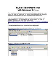
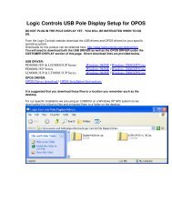
TP57/58/5900 G Jumper Setting
TP57/58/5900 G Jumper Setting
TP57/58/5900 G Jumper Setting

You also want an ePaper? Increase the reach of your titles
YUMPU automatically turns print PDFs into web optimized ePapers that Google loves.
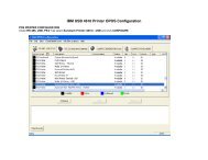
<strong>TP57</strong>00/TP<strong>58</strong>00/TP<strong>5900</strong>G JUMPER SETTING JP2 : TOUCH SIGNAL SELECTPin 1-32-4 Short : COM4 SignalPin 3-54-6 Short : USB Signal (Reserved) JP4 : PS2 MOUSE SIGNAL LOOPShort :All Open : Default JP6 : 12V DC SUPPLY SELECT FOR CRTShort : 12V DCOpen : AC JP9 : LAN FUNCTION SELECTShort : EnableOpen : Disable JP11 : CMOS DATA CONTROLPin 1-2 Short : Clear CMOSPin 2-3 Short : Normal JP12 : Reservedalways short JP13 : COM1/COM2 DC SUPPLY SELECTPin 1-3 Short : COM1 Pin9 connected to 5 V DCPin 3-5 Short : COM1 Pin9 connected as RIPin 2-4 Short : COM2 Pin9 connected to 5 V DCPin 4-6 Short : COM2 Pin9 connected as RI JP14 : COM3/COM4 DC SUPPLY SELECTPin 1-3 Short : COM3 Pin9 connected to 5 V DCPin 3-5 Short : COM3 Pin9 connected as RIPin 2-4 Short : COM4 Pin9 connected to 5 V DCPin 4-6 Short : COM4 Pin9 connected as RI JP16 : SOFTWARE AWARENESS OF UPS STATUSPin 1-2 Short : Normal (DCD signal)Pin 2-3 Short : Detect UPS status JP34 : MX scale IC usePin 1-2 , 3-4 Short : Use TP076/TP077All Open : Use TP056/TP057/TP066/TP067
UPS BatteryConnectorPowerSwitchSystem FanConnectorPowerJack<strong>TP57</strong>00G COMPONENT SIDE<strong>TP57</strong>00G SOLDER SIDEKBMSAUDIOLANJP36JP37JP38IDE PowerConnectorJP8CRLEDLPTCPU FanConnectorU1DIM1DIM2VGAPCI1U2COM3COM4BAT1JP6COM1COM2JP12U11U3LCD1JP9JP162JP132JP11JP14A1B2JP34CF1JP2Riser CardControlJP3IDE1JP4