2. installation procedure for optional equipment - toshiba tec europe
2. installation procedure for optional equipment - toshiba tec europe
2. installation procedure for optional equipment - toshiba tec europe
- No tags were found...

You also want an ePaper? Increase the reach of your titles
YUMPU automatically turns print PDFs into web optimized ePapers that Google loves.
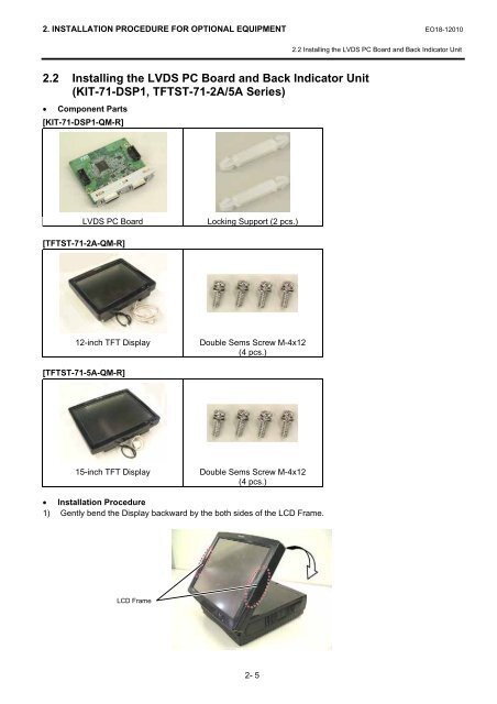
<strong>2.</strong> INSTALLATION PROCEDURE FOR OPTIONAL EQUIPMENT EO18-12010<strong>2.</strong>2 Installing the LVDS PC Board and Back Indicator Unit<strong>2.</strong>2 Installing the LVDS PC Board and Back Indicator Unit(KIT-71-DSP1, TFTST-71-2A/5A Series)• Component Parts[KIT-71-DSP1-QM-R]LVDS PC BoardLocking Support (2 pcs.)[TFTST-71-2A-QM-R]12-inch TFT DisplayDouble Sems Screw M-4x12(4 pcs.)[TFTST-71-5A-QM-R]15-inch TFT DisplayDouble Sems Screw M-4x12(4 pcs.)• Installation Procedure1) Gently bend the Display backward by the both sides of the LCD Frame.LCD Frame2- 5