02030110 - Cafet Innova
02030110 - Cafet Innova
02030110 - Cafet Innova

Create successful ePaper yourself
Turn your PDF publications into a flip-book with our unique Google optimized e-Paper software.
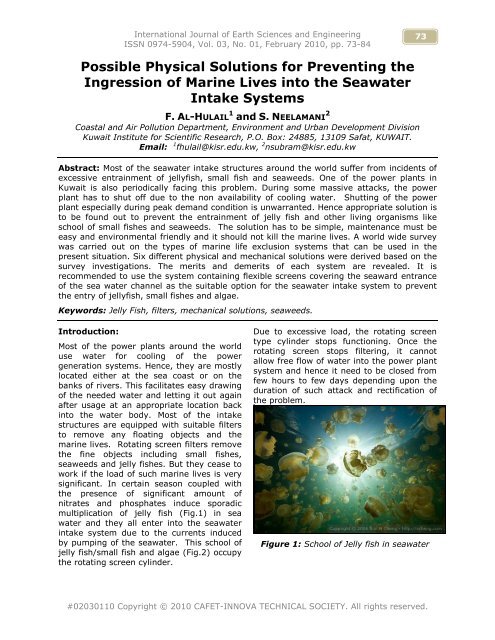
International Journal of Earth Sciences and EngineeringISSN 0974-5904, Vol. 03, No. 01, February 2010, pp. 73-8473Possible Physical Solutions for Preventing theIngression of Marine Lives into the SeawaterIntake SystemsF. AL-HULAIL 1 and S. NEELAMANI 2Coastal and Air Pollution Department, Environment and Urban Development DivisionKuwait Institute for Scientific Research, P.O. Box: 24885, 13109 Safat, KUWAIT.Email: 1 fhulail@kisr.edu.kw, 2 nsubram@kisr.edu.kwAbstract: Most of the seawater intake structures around the world suffer from incidents ofexcessive entrainment of jellyfish, small fish and seaweeds. One of the power plants inKuwait is also periodically facing this problem. During some massive attacks, the powerplant has to shut off due to the non availability of cooling water. Shutting of the powerplant especially during peak demand condition is unwarranted. Hence appropriate solution isto be found out to prevent the entrainment of jelly fish and other living organisms likeschool of small fishes and seaweeds. The solution has to be simple, maintenance must beeasy and environmental friendly and it should not kill the marine lives. A world wide surveywas carried out on the types of marine life exclusion systems that can be used in thepresent situation. Six different physical and mechanical solutions were derived based on thesurvey investigations. The merits and demerits of each system are revealed. It isrecommended to use the system containing flexible screens covering the seaward entranceof the sea water channel as the suitable option for the seawater intake system to preventthe entry of jellyfish, small fishes and algae.Keywords: Jelly Fish, filters, mechanical solutions, seaweeds.Introduction:Most of the power plants around the worlduse water for cooling of the powergeneration systems. Hence, they are mostlylocated either at the sea coast or on thebanks of rivers. This facilitates easy drawingof the needed water and letting it out againafter usage at an appropriate location backinto the water body. Most of the intakestructures are equipped with suitable filtersto remove any floating objects and themarine lives. Rotating screen filters removethe fine objects including small fishes,seaweeds and jelly fishes. But they cease towork if the load of such marine lives is verysignificant. In certain season coupled withthe presence of significant amount ofnitrates and phosphates induce sporadicmultiplication of jelly fish (Fig.1) in seawater and they all enter into the seawaterintake system due to the currents inducedby pumping of the seawater. This school ofjelly fish/small fish and algae (Fig.2) occupythe rotating screen cylinder.Due to excessive load, the rotating screentype cylinder stops functioning. Once therotating screen stops filtering, it cannotallow free flow of water into the power plantsystem and hence it need to be closed fromfew hours to few days depending upon theduration of such attack and rectification ofthe problem.Figure 1: School of Jelly fish in seawater#<strong>02030110</strong> Copyright © 2010 CAFET-INNOVA TECHNICAL SOCIETY. All rights reserved.
74 Possible Physical Solutions for Preventing the Ingression of MarineLives into the Seawater Intake SystemsFigure 2: Algae in the seawaterCountries like Kuwait consume large amountof power per capita during summer in orderto meet the air conditioning loads. The daytime temperature in summer raises morethan 50o C and hence power cut or shortageis a painful problem.One of the power plant in Kuwaitexperiences periodic entrainment problem ofJelly fish, school of small fish and seaweedsand algae. The solution to be adopted has tomeet certain important criteria:a) The solution must be simple androbustb) The maintenance must be easyc) It must be cost competitive, andd) It must be environment friendly andshould not kill the marine organismsThis paper gives the details of the solutions,their merits and demerits and finalrecommendation for a suitable solution.Study Approach:First a survey of different types of marinelife exclusion systems used around the worldis carried out. In order to get the up to dateinformation, the issue of clogging of rotatingseawater intake screen was raised throughcoastal list, a network of contact for coastalresearchers around the world, which ismanaged by University of Deleware,USA.Responses from different companies,who manufacture different types of marinelife exclusion systems, were obtained. Fromaround the world, information from differentresearchers who work on this topic and fromorganizations that are facing similarproblems, were gathered. Publishedliteratures on the topics related toprevention of Jelly fish, small fishes andalgae entry into the intake systems of powerplants were collected.From our own experience, six differentpossible mechanical solutions for thechannel type seawater intake systems areformulated. The merits and demerits of eachsystem are identified. Finally, it isrecommended to use the system containingflexible screens covering the seawardentrance of the sea water intake channel asthe suitable option for the present system toprevent the entry of jellyfish, small fishesand algae.Type of Seawater Intake Systems:Around the world, the following three majorsystems are used for drawing water fromthe sea:• Open channel system (Fig.3).• Submarine pipeline system.• Pump house in the offshore waterlinked with the power plant by anapproach trestle resting on numberof piles (Fig.4)Figure 3: Open channel seawater intakesystem.International Journal of Earth Sciences and EngineeringISSN 0974-5904, Vol. 03, No. 01, February 2010, pp. 73-84
76 Possible Physical Solutions for Preventing the Ingression of MarineLives into the Seawater Intake SystemsThe following six different physical andmechanical schematic solutions are derivedbased on the investigations. Surfaceemerging porous rubble mound breakwaterplus geo-fabric type filter barrier (Fig.5).1. Partially submerged wall + filtering ofwater using submerged rubble and geofabricfilters (Fig.6)2. Flexible perforated vertical screensspanning the width of channels (Fig.7)3. Flexible screens at the entrance ofthe channel (Fig.8)4. Intake from East channel usingtunnels/pipelines (Fig.11)5. Drum screen system spanning thewidth of the channel (Fig.12)The basic descriptions, merits and demeritsof each system are provided below. Thescheme is schematic and a detailed analysisand design need to be carried out oncezeroing down to a particular system is done.Surface Emerging Porous Rubble MoundBreakwater Plus Geo-Fabric Type FilterBarrier:Working Principle:The system consists of a static filter barrier,constructed using rubbles and spanning thewhole 364.5 m width of the seawater intakechannel. The top level should be kept wellabove the highest high water level toprevent spilling of water over thebreakwater. The inner layers should befilled with natural stones of smaller sizesand the outer layer with bigger sizes.Figure 5: Surface emerging porous rubble mound breakwater plus geo-fabric type filterbarrierSuitable non woven geo-fabric filter shouldoccupy the space between the outer andinner stones. Typical c/s view of this type offilter barrier is shown in Fig.6. The mainfunction of the geo-fabric is to filter thesmallest fish available at the seaward side ofthis structure. It is essential to design andprovide a suitable sized sediment trap onthe seaward side of the filter barrier, so thatmost of the sediments moving inside thechannel are allowed to settle down in thetrap and the geo-fabric filter is free fromclogging by the fine silt and clay particles.The pumping of water creates a potentialenergy difference between the sides of thefilter barrier, which is the driving force forthe water to enter through the filter. Darcylaw governs the design for the flow. Sincethe approach velocity is 10 cm/sec, thepresence of the filter barrier (With about30% to 40% porosity of the natural stones)will increase the flow velocity through thebarrier pores.Merits:• The material is stone, which isnatural and hence the life will be longer andthere is no need of any replacement orexchange.• There are non woven geo fabricsavailable for every need in the engineeringworks; it is possible to select appropriatetype of the geo-textile, which suits thepresent requirements.International Journal of Earth Sciences and EngineeringISSN 0974-5904, Vol. 03, No. 01, February 2010, pp. 73-84
F. AL-HULAIL and S. NEELAMANI77• This system filters even very smallfishes and is governed by the pore size.• It is environment friendly and doesnot harm or kill any marine life.Demerits:• The pores of the geo-textile layermay get blocked over a period of few yearsby the fine sediments, algae and othermarine organisms. Hence replacement ofthe geo-fabric may be required once in fewyears time, which depends on the rate ofblocking of the pores. Hence continuousmonitoring is needed.• It may be required to clean theseaside face of the filter periodically usinghigh pressure air or water in order to keepthe filter surface free from blockage.Partially Submerged Wall + Filtering ofWater Using Submerged Rubble andGeo-fabric Filters:Working Principle:This system consists of a partially immersedwall spanning the whole 364.5 m width ofthe channel and a submerged stone pluswoven geo-fabric filter layer as shown inFig.7Figure 6: Partially submerged wall + filtering of water using submerged rubble and geofabricfiltersLike Fig.6, the sediments can be allowed todeposit in a trap as shown in the Fig.7. Themain difference between Fig.6 and 7 is thatin Fig.7, the water is filtered by thesubmerged infiltration gallery. The filtermaterials are not in contact with the floatingobjects at any stage. The flow of waterthrough the infiltration gallery is activateddue to the potential difference between thesides of this filter barrier, which is causeddue to pumping by the cooling water pumps.Merits:• The main filter material is naturalstones and hence the life will be longer andthere is no need of any replacement over aperiod of time.• As stated earlier, there are manyvarieties of non woven geo fabrics availablefor every need in the engineering works.Hence it is possible to select appropriatetype (Thickness, pore size, material of thegeo textile suitable for the saline watercondition etc) of the geo-textile, which suitsthe present requirements.• This technique can filter even verysmall fishes and larvae, which is governedby the pore size of the geo fabric layer to beused.• There is no interference by thefloating debris.• It is environment friendly and doesnot harm or kill any marine life.International Journal of Earth Sciences and EngineeringISSN 0974-5904, Vol. 03, No. 01, February 2010, pp. 73-84
78 Possible Physical Solutions for Preventing the Ingression of MarineLives into the Seawater Intake Systems• The pores of the geo-textile layermay get blocked over a period of few yearsby the fine sediments, algae and othermarine organisms. Hence replacement ofthe geo-fabric may be required once in fewyears time, which depends on the rate ofblocking of the pores.Flexible Perforated Vertical ScreensSpanning the Width of ChannelsWorking Principle:Fig.8 shows the c/s view of the schematicarrangement of the flexible perforatedmarine life filtering system, which need tospan the whole width of the channel.This system basically consists of three rowsof perforated screens covering the completewater flow area.Figure 7: Flexible perforated vertical screens spanning the width of channelsEach filter screen can be held to the groundby suitable deadweights. Each screen canbe provided with a dedicated screen rollersystem for rolling it up, when ever requiredfor maintenance purpose. The system canbe placed permanently at a particularlocation by using fixed mechanical handlingsystem or can be made movable by fixingthem on mobile type mechanical handlingsystems. The type of material, pore size etcneed to be selected by keeping in mind theambient conditions. The purpose ofproviding 3 rows is for progressive filteringand to make sure that the system worksuninterrupted round the clock for the yearsahead. This can be achieved because evenif the seaward end of the screen is blockedby algae, marine growth and fine materials,it can be removed and maintained and refixedat the side closer to the pump house.For example, let us assume at the beginningthe filters screens are in the order 1, 2 and3 (No.1 is on the pump side, 2 is in themiddle and 3 is on the sea side). Aftercertain period (Whenever maintenance isrequired to clean the filter screen), screen 3can be removed, blockages cleaned andreinstalled such that the screen system isnow in the order 3, 1 and 2. Now aftercertain period, the sea side screen (No.2)can be moved out for cleaning andmaintenance and reinstalled in the order 2,3 and 1. This cycle can continue asdiscussed above.International Journal of Earth Sciences and EngineeringISSN 0974-5904, Vol. 03, No. 01, February 2010, pp. 73-84
F. AL-HULAIL and S. NEELAMANI79Merits:• The system can filter all floatingdebris, jelly fish, algae and small fishes veryeffectively due to the filtering effect of 3layers.• Since the filter is made up of suitablesynthetic material and is very thin, it will notoffer high resistance to the flow of water.Hence the flow velocity in the immediatevicinity of the filter layer will be closer to theapproaching velocity of water (Maximumapproach velocity is about 10 cm/sec andhence the flow velocity at the vicinity of thefilter will be little more than 10 cm/s.• Even if one of the filter screen isremoved for maintenance, the tworemaining screen will effectively do thefiltering work.• It is environment friendly and doesnot harm or kill any marine life.Demerits:• The seaward side of the filter screenneeds periodic maintenance. The interval ofmaintenance depends upon the rate ofblockage of the filter screens. Hencecontinuous monitoring is required.• The floating debris on the seawardside of the screen needs to be clearedperiodically in order to reduce the blockageof the seaward screen.• The screen is hanging frommechanical handling systems (Either mobileor fixed), which needs periodic maintenance.Flexible Screens at the Entrance of theChannel:Working Principle:The working principle is similar to theprevious one. However the filtering systemis to be installed at the entrance of theintake channel in a circular or any othercurvilinear shape (Fig.8). It consists of twolayers. Each layer is supported by muchnumber of floats and the bottom is fixed atthe sea bed by a number of suitable gravityanchors. At low water level, the filter willtake a cat nary shape with enough slackingand at high water it will be almost verticalwith less slacking.Figure 8: Flexible screens at the entrance of the channelInternational Journal of Earth Sciences and EngineeringISSN 0974-5904, Vol. 03, No. 01, February 2010, pp. 73-84
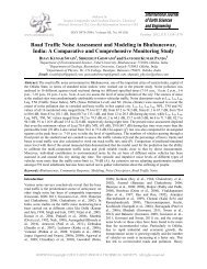
80 Possible Physical Solutions for Preventing the Ingression of MarineLives into the Seawater Intake SystemsThe Marine Life Exclusion Systems(mles) from Gunderboom, USA:he Gunderboom MLES USA is one of theleading manufacturer and supplier of systemsimilar to the above one. They claim thattheir system reduces the impact of intakestructures on aquatic organisms bypreventing entrainment and impingement,while protecting the structure from marinelife intrusion.The MLES also reduces operating andmaintenance costs and helps prevent plantshutdowns. Gunderboom’s MLES is awater-permeable barrier that keeps fisheggs, larvae and other aquatic organisms asafe distance away from an industrial intakestructure. Engineered, manufactured andsupported by them, the MLES preventingboth impingement and entrainment ofichthyic plankton and juvenile aquatic life.State and federal agencies in USA havedeemed the MLES as the Best TechnologyAvailable under the Clean Water Act, Section316(b), USA. (Fig. 10)The system comprised of a pocket formedby two layers of treated fabric, thepatented, full-water-depth MLES curtain iseither suspended by flotation billets andanchored in place, or integrated into existingshoreline intake structures. Sealed againstthe sea floor and shoreline structures, theMLES completely surrounds the intakestructure, preventing targeted planktonicand neustonic organisms from entering thesystem. Since the surface area of theMLES is large compared to an intakescreen, water velocity through theGunderboom curtain is up to 98 percent lessthan the velocity near the intake structure.Low water velocity enables even small fishlarvae to drift away from the boom.Figure 10: MLES of Gunderboom, USA inLovette StationAutomatic AirBurst Cleaning System:Sediment and passively floating organismsdrawn onto the fabric are freed whenGunderboom’s AirBurst cleaning systemroutinely releases high-pressure air at theboom’s base (Fig.11).Figure 11: AirBurst cleaning System ofGunderboom, USAInternational Journal of Earth Sciences and EngineeringISSN 0974-5904, Vol. 03, No. 01, February 2010, pp. 73-84
F. AL-HULAIL and S. NEELAMANI81Bursts of compressed air shake each fabricpanel, releasing deposits and ensuring asteady flow of water through the curtain.Minimal Impact on Aquatic Life:Data from worst-case test conditions showsthat contact with an operating MLES doesnot adversely affect fish eggs or larvae.Fossil Fuel Conservation:Daily operation of dry cooling towersconsumes large amounts of fossil fuels. Acost-effective, ecologically sound andaesthetically pleasing alternative,Gunderboom’s MLES enables plantoperators to maintain water intake levels,even during periods of aquatic migration.Merits:• Availability of well proven companiesto deliver MLES which is suitable for theproblems faced here.• Environment friendly and noimpingement and entrainment problem ofmarine organisms.• Proven Air Burst cleaning system andhence there is no need to remove the filtersout of water for periodic cleaning.Demerits:• The system may be expensive due tothe quality of materials used for the filteringsystem, electronic monitoring equipmentsand automatic airburst cleaning systems.Figure 11: Intake from East channel using tunnels/pipelinesIntake from Nearby Intake StructureUsing Tunnels/Pipelines Connecting theTwo Intake Structures:Working Principle:It is already known that the power plantintake at the eastern side is not facing theingression of jelly fish and algae problemsfaced by the power plant in the westernside. This is due to the fact that the seawater intake mouth is far away from theshore for the eastern side plant, whencompared to the channel mouth of westernside plant and the favorable hydrodynamicflow conditions which flushes out the jellyfish and algae when western side plant isInternational Journal of Earth Sciences and EngineeringISSN 0974-5904, Vol. 03, No. 01, February 2010, pp. 73-84
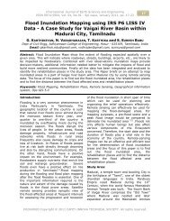
82 Possible Physical Solutions for Preventing the Ingression of MarineLives into the Seawater Intake Systemsattacked by them. Hence logically it iscorrect to take water from far field (fromdeeper portions) in order to minimize theingression of jelly fish and algae into thewestern side power plant intake channel.This can be either achieved by extending thechannel length of western side plant or takewater from the eastern power plant. Theproposal is as follows:-• Replace the existing debris screen atthe mouth of the western power plant with afine size screen (Say 2 mm pore size) andextend it vertically up to the seabed. Thiswill help entry of floating debris, jelly fish,fishes of small sizes (Fig.10).• Connect the western power plantintake with the eastern side power plantintake through tunnels of pipelines ofsuitable size so that the water can go intothe western side power plant intake fromthe eastern power plant intake.• Since water is entering both from theWestern power plant channel mouth andeastern power plant intake pool, the velocityof entry at eastern power plant mouth mayincrease moderately.Merits:In this proposed scheme, the water forDWPP is available both from the DWPPchannel entrance and DEPP pool and hencethe entry velocity at the DWPP intakechannel mouth can be kept even less than10 cm/sec and hence there will be lessblockage effect due to debris, algae andother materials at the proposed fullyextending screen and the DWPP channelmouth.Demerits:• The velocity of water entrance at theeastern side power plant channel mouthmay increase compared to the presentvelocity level.• Since it is proposed to replace thewestern side power plant’s entrancechannel mouth screen with finer sizedscreen and extension up to the sea bed, itneeds more periodic maintenance comparedto the present level of maintenance.• This proposal needs to be studied indetail from Hydrodynamic flow and its effecton the movement of Jelly fish, algae andother floating debris.Figure 12: Rolling drum screen system spanning the width of the channelDrum Screen System:Working Principle:The system consists of a perforated rollingscreen covering the whole width of theDWPP intake channel. The rolling screenmay be of 3 to 4 m dia and the size of theperforations needs to be selected based onthe size of larvae and fish eggs which can beallowed to pass into the cooling water intakesystem. The outer surface of the screen willhave many number of collection bucketsfixed on its surface. When the screen isrolling in the clockwise direction, the bucketwill bail out the debris, jelly fish, algae andfish and they will be dumped on a beltInternational Journal of Earth Sciences and EngineeringISSN 0974-5904, Vol. 03, No. 01, February 2010, pp. 73-84
F. AL-HULAIL and S. NEELAMANI83conveyor running perpendicular to theFig.12 and are disposed o the land area forfurther removal using Lorries. When thereis no attack by the marine life, the screencan be rolled with minimum speed just forremoval of floating debris. During sporadicattack by jelly fish and algae, the speed ofrolling can be increased to take care of therate of attack and quick clearing of theattacking masses. Water jetting from withinthe rolling cylinder can jet out high pressurewater periodically for cleaning the outersurface of the perforated plate on the rollersurface.Instead of circular rolling screens, we can gofor inclined moving screens. In this case, thedrive to move the screen will be both at thebottom (Near the sea floor) and at top(Above the water surface). The movingscreen allows continuous dumping of thehooked up jelly fish/seaweed and othermarine organisms on a belt conveyor, whichwill be located at the rear side of the toplevel drive. The materials falling on the beltconveyor is then dumped on a vacant site inthe power plant area, allowed to dry andmay be either used for any suitablepurposes or dumped in a suitable placeaway from the power plant.Merits:• The concept is simple.• Rolling screen removes the floatingobjects continuously even when the marinelife attack is minimum and hence there is noneed for other type of floating debrisremoval adopted at present.Demerits:• It is a mechanical system and henceneeds periodic maintenance.• All the marine life which gets into thebucket attached on the rolling screen will bekilled in the process.• If the pore size allows the larvae andfish egg entry into the cooling water system,they will also get killed.Other Recent Solutions for QualityWater Intake in Power and DesalinationPlants:During the study, the project team comesacross a solution called Seawater intake byhorizontal directional drains. This technologyis introduced by Catalana de Perforacions(CP), Spain and is called Neodrentechnology. It is invented and developed byCP based on Horizontal directional drilling,being the first unit installed in 1996.Basically the system contains manynumbers of directed drilled horizontal drainsbelow the sea bed. The number of drains, itsdiameter and length etc depends on theintake capacity. CP has done projects atdifferent seawater intake sites for capacitiesup to 371,520 m 3 /day. It is claimed thatthe water derived from the drain is ofsuperior quality due to the natural filtrationby the sub sea bed rocks. Hence no furthertreatment (like chlorination etc) is requiredfor the water and can be used directly forcooling and desalination purposes. Theeconomics needs to be worked out. Dueattention is given for future power anddesalination plants in Kuwait.Contact Details of Companies Involvedin Mles Business around the World:• Brackett Green USA, Inc., 1335Regents Park Drive, Suite 140, Houston,Texas 77058, USA. Tel: +1 281 480 7955,Fax: +1 281 480 8225, E-mail:info@bgusa.com• E. BEAUDREY & CIE., 14 BoulevardOrnano, 75018 Paris, France, Phone: (33-1)42-57-14-35, Fax: (33-1) 42-64-74-62.• GUNDERBOOM, Inc., 210 HickmanDrive, Sanford, FL 32771. Phone: 407-548-2200, Toll-Free: 888-345-2666, Fax: 407-548-2230. Cell: 321-662-4412, Web:www.gunderboom.comConclusions:Marine life ingression into the seawaterintake system is a worldwide pain stackingtechnical problem. A world wide survey iscarried out to obtain the different types ofmarine life exclusion systems used in thesea water intake systems, companies whichmake such systems and R&D works inprogress to solve such problemseconomically with due environmentalconsiderations to safeguard the life ofmarine organisms. Six different types ofMechanical/Physical marine lifeexclusion/filtering systems were identifiedInternational Journal of Earth Sciences and EngineeringISSN 0974-5904, Vol. 03, No. 01, February 2010, pp. 73-84
84 Possible Physical Solutions for Preventing the Ingression of MarineLives into the Seawater Intake Systemsbased on the present study. The operatingprinciples, merits and demerits of thedifferent systems are emphasized. It isrecommended to use the system containingflexible screens covering the seawardentrance of the sea water channel as thesuitable option for the seawater intakesystem to prevent the entry of jellyfish,small fishes and algae. Further investigationis required to increase the technicalknowledge of different systems identified inthis study.References:[1] Campbell, R. L., and Jones, A. T. (2005).Appropriate disposal of effluent fromcoastal desalination facilities,Desalination, Vol. 182, pp.359-366.[2] Hunt, H. C. (2000). Filtered seawatersupplies-Naturally. Desalination andWater Reuse. Vol. 6/2, pp. 32-37.International Journal of Earth Sciences and EngineeringISSN 0974-5904, Vol. 03, No. 01, February 2010, pp. 73-84