This manual must be read thoroughly and always - esco ...
This manual must be read thoroughly and always - esco ...
This manual must be read thoroughly and always - esco ...

Create successful ePaper yourself
Turn your PDF publications into a flip-book with our unique Google optimized e-Paper software.
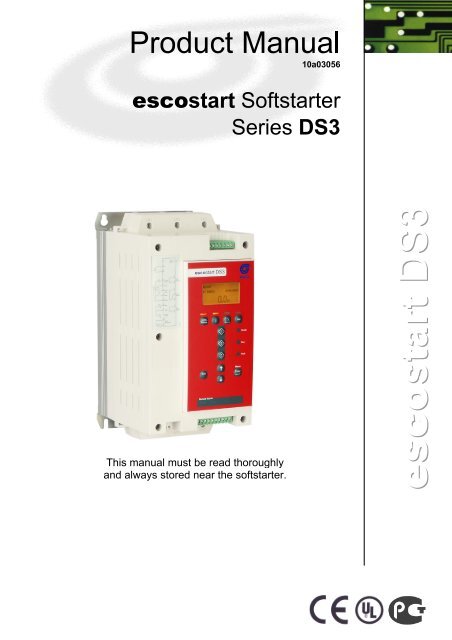
<strong>This</strong> <strong>manual</strong> <strong>must</strong> <strong>be</strong> <strong>read</strong> <strong>thoroughly</strong><br />
<strong>and</strong> <strong>always</strong> stored near the softstarter.<br />
10a03056
Product Manual <strong>esco</strong>start DS3 1<br />
Contents<br />
1. Caution Statements .......................................................................................................3<br />
2. Declaration of conformity..............................................................................................4<br />
3. Introduction ....................................................................................................................5<br />
3.1 Feature List............................................................................................................................................. 5<br />
3.2 Specifications ......................................................................................................................................... 5<br />
4. Installation ....................................................................................................................12<br />
4.1 Physical Installation .............................................................................................................................. 12<br />
4.2 Control Terminals ................................................................................................................................. 13<br />
4.3 Control Wiring....................................................................................................................................... 13<br />
4.4 Relay Outputs....................................................................................................................................... 14<br />
4.5 Motor Thermistors ................................................................................................................................ 14<br />
4.6 Power Terminations.............................................................................................................................. 15<br />
4.7 Schematic diagrams ............................................................................................................................. 16<br />
5. Power Circuits ..............................................................................................................17<br />
5.1 Motor Connection ................................................................................................................................. 17<br />
5.2 Bypass Contactor ................................................................................................................................. 21<br />
5.3 Main Contactor ..................................................................................................................................... 21<br />
5.4 Circuit Breaker...................................................................................................................................... 21<br />
5.5 Power Factor Correction....................................................................................................................... 21<br />
5.6 Fuses.................................................................................................................................................... 22<br />
5.7 Earth Terminals .................................................................................................................................... 25<br />
6. Operation ......................................................................................................................26<br />
6.1 Keypad <strong>and</strong> Feedback.......................................................................................................................... 26<br />
6.2 Start, Stop <strong>and</strong> Reset Comm<strong>and</strong>s ........................................................................................................ 28<br />
6.3 Soft Start Methods................................................................................................................................ 29<br />
6.4 Stop Methods ....................................................................................................................................... 32<br />
6.5 Jog Operation ....................................................................................................................................... 35<br />
6.6 Inside Delta Operation.......................................................................................................................... 36<br />
7. Programming Menu .....................................................................................................37<br />
7.2 Quick Setup .......................................................................................................................................... 37<br />
7.3 St<strong>and</strong>ard Menu ..................................................................................................................................... 39<br />
7.4 Extended Menu .................................................................................................................................... 40<br />
7.5 Parameter Descriptions ........................................................................................................................ 43<br />
7.6 Adjustment Lock ................................................................................................................................... 61<br />
7.7 Access Code ........................................................................................................................................ 62<br />
7.8 Setup Tools .......................................................................................................................................... 62<br />
8. Logs Menu ....................................................................................................................65<br />
8.2 Trip Log ................................................................................................................................................ 65<br />
8.3 Event Log ............................................................................................................................................. 65<br />
8.4 Performance Counters ......................................................................................................................... 65<br />
Product Manual <strong>esco</strong>start DS3 1
2 Product Manual <strong>esco</strong>start DS3<br />
9. Application Examples ..................................................................................................66<br />
9.1 Installation with Main Contactor ............................................................................................................66<br />
9.2 Installation with Bypass Contactor ........................................................................................................67<br />
9.3 Emergency Run Operation....................................................................................................................68<br />
9.4 Auxiliary Trip Circuit ..............................................................................................................................69<br />
9.5 Soft Braking...........................................................................................................................................70<br />
9.6 Two Speed Motor ..................................................................................................................................71<br />
10. Troubleshooting ...........................................................................................................73<br />
10.1 Protection Responses ...........................................................................................................................73<br />
10.2 Trip Messages.......................................................................................................................................73<br />
10.3 General Faults.......................................................................................................................................76<br />
11. Accessories ..................................................................................................................78<br />
11.1 Communication Modules.......................................................................................................................78<br />
11.2 Finger Guard Kit ....................................................................................................................................78<br />
11.3 PC Software ..........................................................................................................................................78<br />
12. Bus Bar Adjustment Procedure ..................................................................................79<br />
2 Product Manual <strong>esco</strong>start DS3
Product Manual <strong>esco</strong>start DS3 3<br />
1. Caution Statements<br />
<strong>This</strong> symbol is used throughout this <strong>manual</strong> to draw attention to topics of special importance to the<br />
installation <strong>and</strong> operation of <strong>esco</strong>start DS3 soft starters.<br />
Caution Statements cannot cover every potential cause of equipment damage but can highlight common<br />
causes of damage. It is the installer's responsibility to <strong>read</strong> <strong>and</strong> underst<strong>and</strong> all instructions in this <strong>manual</strong> prior<br />
to installing, operating or maintaining the soft starter, to follow good electrical practice including applying<br />
appropriate personal protective equipment <strong>and</strong> to seek advice <strong>be</strong>fore operating this equipment in a manner<br />
other than as descri<strong>be</strong>d in this <strong>manual</strong>.<br />
The examples <strong>and</strong> diagrams in this <strong>manual</strong> are included solely for illustrative purposes. The information<br />
contained in this <strong>manual</strong> is subject to change at any time <strong>and</strong> without prior notice. In no event will<br />
responsibility or liability <strong>be</strong> accepted for direct, indirect or consequential damages resulting from the use or<br />
application of this equipment.<br />
WARNING - ELECTRICAL SHOCK HAZARD<br />
<strong>esco</strong>start DS3 soft starters contain dangerous voltages when connected to mains voltage. Only a<br />
competent electrician should carry out the electrical installation. Improper installation of the motor or<br />
the soft starter may cause equipment failure, serious injury or death. Follow this <strong>manual</strong> <strong>and</strong> local<br />
electrical safety codes.<br />
SHORT CIRCUIT<br />
<strong>esco</strong>start DS3 soft starters are not short circuit proof. After severe overload or short circuit, the<br />
operation of the soft starter should <strong>be</strong> fully tested by an authorised service agent.<br />
GROUNDING AND BRANCH CIRCUIT PROTECTION<br />
It is the responsibility of the user or person installing the soft starter to provide proper grounding <strong>and</strong><br />
branch circuit protection according to local electrical safety codes.<br />
Product Manual <strong>esco</strong>start DS3 3
4 Product Manual <strong>esco</strong>start DS3<br />
2. Declaration of conformity<br />
In industrial linguistic usage the drive controllers of the type series <strong>esco</strong>start DS3 are called "devices",<br />
however, in the sense of the "law on the safety of equipment", the "EMC-law" or the "EC-machinery directive"<br />
they are not devices or machines <strong>read</strong>y for use or connection but they are components. It is only possible to<br />
define their final function, when these components are integrated into the design <strong>and</strong> construction of the user.<br />
To <strong>be</strong> able to use the devices to their intended purpose, it requires power supply networks according<br />
to DIN EN 50160 (IEC 60038).<br />
The user takes the responsibility that the user's design <strong>and</strong> construction comply with the applicable legal<br />
provisions.<br />
The commissioning is strictly forbidden as long as the conformity of the final system with the guidelines<br />
89/392/EWG (Machinery directive) <strong>and</strong> 73/23/EWG (Low voltage directive) is not proved.<br />
The devices of the series are electrical equipment that is used in industrial electrical power installations. They<br />
are designed for application in machines, in order to reduce the starting torque <strong>and</strong> starting current peaks as<br />
well as the tripping torque of drives with three-phase induction motors. With due regard to the installation<br />
guidelines they meet the following requirements:<br />
Emitted interference: Continuous duty EN 61000-6-3:2005<br />
Acceleration, decel. EN 60947-4-2, IEC 60947-4-2<br />
Immunity to interference: EN 61000-6-2:2005<br />
<strong>esco</strong>start DS3 has <strong>be</strong>en designed to meet the st<strong>and</strong>ards specified in IEC 60947-4-2: Ed2.2 2007-02 Low<br />
voltage switchgear – Part 4-2 Contactors <strong>and</strong> motor-starters – AC Semiconductor motor controllers <strong>and</strong><br />
starters, for low voltage safety, operation <strong>and</strong> EMC.<br />
<strong>This</strong> product has <strong>be</strong>en designed as Class A equipment. Use of this product in domestic environments may<br />
cause radio interference, in which case the user may <strong>be</strong> required to employ additional mitigation methods.<br />
4 Product Manual <strong>esco</strong>start DS3
Product Manual <strong>esco</strong>start DS3 5<br />
3. Introduction<br />
The <strong>esco</strong>start DS3 is an advanced digital soft start solution for motors from 7 kW to 800 kW. <strong>esco</strong>start DS3<br />
soft starters provide a complete range of motor <strong>and</strong> system protection features <strong>and</strong> have <strong>be</strong>en designed for<br />
reliable performance in the most dem<strong>and</strong>ing installation situations.<br />
3.1 Feature List<br />
Extensive starting <strong>and</strong> stopping options<br />
� AAC Adaptive Acceleration Control<br />
� Constant current<br />
� Current ramp<br />
� Timed voltage ramp soft stop<br />
� Brake<br />
Models for all connection requirements<br />
� 23 A to 1600 A (nominal)<br />
� 200 VAC to 525 VAC<br />
� 380 VAC to 690 VAC<br />
� Internally bypassed up to 220 A<br />
� In-line or inside delta connection (auto-detect)<br />
Inputs <strong>and</strong> outputs<br />
� Remote control inputs<br />
(3 x fixed, 1 x programmable)<br />
� Relay outputs<br />
(3 x programmable)<br />
� Analog output<br />
� DeviceNet, Modbus or Profibus communication<br />
modules<br />
3.2 Specifications<br />
3.2.1 Model Code<br />
Easy-to-<strong>read</strong> display with comprehensive feedback<br />
� Multi-language feedback<br />
� Multiple status screens <strong>and</strong> performance graphs<br />
� Date <strong>and</strong> time stamped event logging<br />
� Operational counters (num<strong>be</strong>r of starts, hours run,<br />
kWh)<br />
� Performance monitoring (current, voltage, power<br />
factor, kWh)<br />
� User-programmable monitoring screen<br />
Customisable protection<br />
� Motor overload<br />
� Excess start time<br />
� Undercurrent<br />
� Instantaneous overcurrent<br />
� Current imbalance<br />
� Mains frequency<br />
� Input trip<br />
� Motor thermistor<br />
� Power circuit<br />
� Phase sequence<br />
DS3 - 2 5 5 - 4 0 0 H N <strong>esco</strong>start DS3, 255A, 400V, int. 24V, ext. bypass<br />
bypass<br />
integrated<br />
N not integrated<br />
control voltage<br />
H 24VDC control voltage source integrated<br />
L external 24VDC control voltage<br />
supply voltage<br />
400 200 bis 525 VAC<br />
softstarter rated current<br />
Product Manual <strong>esco</strong>start DS3 5
6 Product Manual <strong>esco</strong>start DS3<br />
3.2.2 Current Ratings<br />
Contact your local supplier for ratings under operating conditions not covered by these ratings charts.<br />
Current Ratings for Bypass Operation<br />
80 A : AC-53b 3.<br />
5<br />
In-line connection<br />
- 15 : 34<br />
5<br />
Off time (seconds)<br />
Start time (seconds)<br />
Start current (multiple of motor full load<br />
current)<br />
Starter current rating (amperes)<br />
AC53b 3.0-10:350 AC53b 3.5-15:345 AC53b 4.0-20:340 AC53b 4.5-30:330<br />
40 ºC
Product Manual <strong>esco</strong>start DS3 7<br />
Inside delta connection<br />
AC53b 3.0-10:350 AC53b 3.5-15:345 AC53b 4.0-20:340 AC53b 4.5-30:330<br />
40 ºC
8 Product Manual <strong>esco</strong>start DS3<br />
Current Ratings for Continuous Operation (Not bypassed)<br />
351 A : AC-53a 3.5 - 15 : 50 - 6<br />
In-line connection<br />
Starts per hour<br />
On-load duty cycle (%)<br />
Start time (seconds)<br />
Start current (multiple of motor full load<br />
current)<br />
Starter current rating (amperes)<br />
AC53a 3-10:50-6 AC53a 3.5-15:50-6 AC53a 4-20:50-6 AC53a 4.5-30:50-6<br />
40 ºC
Product Manual <strong>esco</strong>start DS3 9<br />
Minimum <strong>and</strong> Maximum Current Settings<br />
The <strong>esco</strong>start DS3 minimum <strong>and</strong> maximum full load current settings depend on the model:<br />
In-line connection Inside delta connection<br />
Model Minimum Maximum Minimum Maximum<br />
DS3-23 5 A 23 A 5 A 34 A<br />
DS3-43 9 A 43 A 9 A 64 A<br />
DS3-50 10 A 50 A 10 A 75 A<br />
DS3-53 11 A 53 A 11 A 79 A<br />
DS3-76 15 A 76 A 15 A 114 A<br />
DS3-97 19 A 97 A 19 A 145 A<br />
DS3-100 20 A 100 A 20 A 150 A<br />
DS3-105 21 A 105 A 21 A 157 A<br />
DS3-145 29 A 145 A 29 A 217 A<br />
DS3-170 34 A 170 A 34 A 255 A<br />
DS3-200 40 A 200 A 40 A 300 A<br />
DS3-220 44 A 220 A 44 A 330 A<br />
DS3-255N 51 A 255 A 51 A 382 A<br />
DS3-360N 72 A 360 A 72 A 540 A<br />
DS3-380N 76 A 380 A 76 A 570 A<br />
DS3-430N 86 A 430 A 86 A 645 A<br />
DS3-620N 124 A 620 A 124 A 930 A<br />
DS3-650N 130 A 650 A 130 A 975 A<br />
DS3-790N 158 A 790 A 158 A 1185 A<br />
DS3-930N 186 A 930 A 186 A 1395 A<br />
DS3-1200N 240 A 1200 A 240 A 1800 A<br />
DS3-1410N 282 A 1410 A 282 A 2115 A<br />
DS3-1600N 320 A 1600 A 320 A 2400 A<br />
Product Manual <strong>esco</strong>start DS3 9
10 Product Manual <strong>esco</strong>start DS3<br />
3.2.3 Dimensions <strong>and</strong> Weights<br />
Model<br />
A<br />
B<br />
A<br />
mm<br />
(inch)<br />
E<br />
B<br />
mm<br />
(inch)<br />
C<br />
mm<br />
(inch)<br />
A<br />
B<br />
D<br />
mm<br />
(inch)<br />
E<br />
mm<br />
(inch)<br />
C C<br />
F<br />
mm<br />
(inch)<br />
10 Product Manual <strong>esco</strong>start DS3<br />
E<br />
G<br />
G<br />
mm<br />
(inch)<br />
F<br />
H<br />
mm<br />
(inch)<br />
I<br />
mm<br />
(inch)<br />
H<br />
I<br />
08718.B<br />
Weight<br />
kg<br />
(lb)<br />
DS3-23<br />
DS3-43 192 3.2<br />
DS3-50 (7.6) (7.1)<br />
DS3-53 156 124 295 278 not not not not<br />
DS3-76 (6.2) (4.9) (11.6) (10.9) applicable applicable applicable applicable 3.5 (7.2)<br />
DS3-97 223 4.8<br />
DS3-100 (8.8)<br />
DS3-105<br />
DS3-145<br />
(10.6)<br />
DS3-170 282 250 438 380 250 not not not not 16<br />
DS3-200<br />
DS3-220<br />
(11.1) (9.8) (17.2) (15.0) (9.8) applicable applicable applicable applicable (35.3)<br />
DS3-255N 390 320 417 400 281 not not not not 25<br />
(15.4) (12.6) (16.4) (15.8) (11.1) applicable applicable applicable applicable (55.1)<br />
DS3-360N 50.5<br />
DS3-380N (111.3)<br />
DS3-430N 430 320 545 522 302 6 105 105 6<br />
DS3-620N (16.9) (12.6) (21.5) (20.6) (11.9) (0.2) (4.1) (4.1) (0.2)<br />
DS3-650N 53.5<br />
DS3-790N<br />
DS3-930N<br />
(118.0)<br />
DS3-1200N 574 500 750 727 361 9 133 129 5 140<br />
DS3-1410N<br />
DS3-1600N<br />
(22.6) (19.7) (29.5) (28.6) (14.2) (0.3) (5.2) (5.1) (0.2) (308.7)<br />
Note<br />
Dimensions F, G, H <strong>and</strong> I are the additional space required for the output <strong>and</strong> input busbars, in<br />
addition to the overall chassis measurement (C).
Product Manual <strong>esco</strong>start DS3 11<br />
3.2.4 Specifications<br />
Supply<br />
Mains voltage (L1, L2, L3)<br />
DS3-400–xxxx .............................................................................................................. 200 VAC ~ 525 VAC (± 10%)<br />
Control voltage (A4, A5, A6)<br />
H .......................................................................................... 110-120 VAC or 220-240 VAC (+ 10% / -15%), 600mA<br />
L .................................................................................................................................................. 24 VAC/VDC ±20%<br />
Mains frequency ......................................................................................................................................... 45 Hz to 66 Hz<br />
Rated insulation voltage to earth ......................................................................................................................... 600 VAC<br />
Rated impulse withst<strong>and</strong> voltage ............................................................................................................................... 4 kV<br />
Form designation .............................................................. Bypassed or continuous, semiconductor motor starter form 1<br />
Short circuit capability<br />
Coordination with semiconductor fuses.................................................................................................................... Type 2<br />
Coordination with HRC fuses ................................................................................................................................... Type 1<br />
DS3-23 to DS3-105 ............................................................................................................ prospective current 10 kA<br />
DS3-145 to DS3-220 .......................................................................................................... prospective current 18 kA<br />
DS3-255N to DS3-930N ..................................................................................................... prospective current 85 kA<br />
DS3-1200N to DS3-1600N ............................................................................................... prospective current 100 kA<br />
Electromagnetic capability (compliant with EU Directive 89/336/EEC)<br />
EMC Emissions................................................................... IEC 60947-4-2 Class B <strong>and</strong> Lloyds Marine No 1 Specification<br />
EMC Immunity.............................................................................................................................................. IEC 60947-4-2<br />
Inputs<br />
Input rating ........................................................................................................................... Active 24 VDC, 8 mA approx<br />
Start (54, 55) .............................................................................................................................................. Normally open<br />
Stop (56, 57) ............................................................................................................................................ Normally closed<br />
Reset (58, 57) .......................................................................................................................................... Normally closed<br />
Programmable input (53, 55) ..................................................................................................................... Normally open<br />
Motor thermistor (64, 65) ........................................................................................................ Trip >3.6 k�, reset
12 Product Manual <strong>esco</strong>start DS3<br />
Heat dissipation<br />
During start ...................................................................................................................................... 4.5 watts per ampere<br />
During run<br />
DS3-23 ~ DS3-53 ........................................................................................................................... ≤ 39 watts approx<br />
DS3-76 ~ DS3-105 ........................................................................................................................ ≤ 51 watts approx<br />
DS3-145 ~ DS3-220 .................................................................................................................... ≤ 120 watts approx<br />
DS3-255N ~ DS3-930N ................................................................................................ 4.5 watts per ampere approx<br />
DS3-1200N ~ DS3-1600N ............................................................................................ 4.5 watts per ampere approx<br />
Certification<br />
CE ........................................................................................................................................................... IEC 60947-4-2<br />
UL / C-UL ............................................................................................................................................................... UL 508<br />
GOST-R ..............................................................................................................................................................................<br />
RoHS ................................................................................................................ Compliant with EU Directive 2002/95/EC<br />
4. Installation<br />
4.1 Physical Installation<br />
2/T1 4/T2<br />
6/T3<br />
1<br />
1/L1 3/L2<br />
5/L3<br />
2/T1 4/T2<br />
6/T3<br />
2<br />
1/L1 3/L2<br />
5/L3<br />
2/T1 4/T2<br />
6/T3<br />
2<br />
3<br />
4<br />
1 DS3-23 ~ DS3-255N: Allow 100 mm (3.94 inches)<br />
<strong>be</strong>tween soft starters.<br />
DS3-360N ~ DS3-1600N: Allow 200 mm (7.88<br />
inches) <strong>be</strong>tween soft starters.<br />
2 DS3-23 ~ DS3-220: Allow 50 mm (1.97 inches)<br />
<strong>be</strong>tween the soft starter <strong>and</strong> solid surfaces.<br />
DS3-255N: Allow 100 mm (3.94 inches) <strong>be</strong>tween<br />
the soft starter <strong>and</strong> solid surfaces.<br />
DS3-360N ~ DS3-1600N: Allow 200 mm (7.88<br />
inches) <strong>be</strong>tween the soft starter <strong>and</strong> solid<br />
surfaces.<br />
3 Soft starters may <strong>be</strong> mounted side by side with<br />
50 mm clearance.<br />
4 The soft starter may <strong>be</strong> mounted on its side.<br />
Derate the soft starter's rated current by 15%.<br />
12 Product Manual <strong>esco</strong>start DS3
Product Manual <strong>esco</strong>start DS3 13<br />
4.2 Control Terminals<br />
Control terminations use 2.5mm 2 plug-in terminal blocks. Unplug each block, complete the wiring, then<br />
reinsert the block.<br />
A4 A5 A6<br />
13 14 21 22 24 33 34<br />
40 41 53 54 55 56 57 58 64 65<br />
1<br />
2<br />
3<br />
13 14 21 22 24 33 34<br />
A4 A5 A6<br />
40 41 53 54 55 56 57 58 64 65<br />
1 Relay outputs 3 Inputs <strong>and</strong> outputs<br />
13, 14 Relay output A 54, 55 Start<br />
21, 22,<br />
24<br />
Relay output B 56, 57 Stop<br />
33, 34 Relay output C 58, 57 Reset<br />
2 Control voltage (model<br />
dependent)<br />
53, 55 Programmable input A<br />
A5, A6 110~120 VAC 64, 65 Motor thermistor input<br />
A4, A6 220~240 VAC 40, 41 Analog output<br />
A5, A6 24 VAC/VDC 55, 41 24 VDC output<br />
NOTE<br />
If you are not using a thermistor, do not short terminals 64, 65.<br />
4.3 Control Wiring<br />
The <strong>esco</strong>start DS3 has three fixed inputs for remote control. These inputs should <strong>be</strong> controlled by contacts<br />
rated for low voltage, low current operation (gold flash or similar).<br />
A B<br />
C<br />
1<br />
54<br />
55<br />
56<br />
57<br />
58<br />
57<br />
A<br />
B<br />
C<br />
2 3<br />
54<br />
55<br />
56<br />
57<br />
58<br />
57<br />
1 Two-wire control<br />
2 Three-wire control<br />
3 Four-wire control<br />
A Start<br />
B Stop<br />
C Reset<br />
Product Manual <strong>esco</strong>start DS3 13<br />
A<br />
B<br />
C<br />
CAUTION<br />
Do not apply voltage to the control input terminals. These are active 24 VDC inputs <strong>and</strong> <strong>must</strong> <strong>be</strong><br />
controlled with potential free contacts.<br />
Cables to the control inputs <strong>must</strong> <strong>be</strong> segregated from mains voltage <strong>and</strong> motor cabling.<br />
54<br />
55<br />
56<br />
57<br />
58<br />
57<br />
08721.A
14 Product Manual <strong>esco</strong>start DS3<br />
4.4 Relay Outputs<br />
The <strong>esco</strong>start DS3 has three programmable relay outputs.<br />
Operation of the programmable outputs is determined by the settings of parameters 7A~7I.<br />
� If assigned to Main Contactor, the output activates as soon as the soft starter receives a start<br />
comm<strong>and</strong> <strong>and</strong> remains active while the soft starter is controlling the motor (until the motor starts a<br />
coast to stop, or until the end of a soft stop).<br />
� If assigned to Run, the output activates when the soft start is complete (when the starting current falls<br />
<strong>be</strong>low 120% of the programmed motor full load current) <strong>and</strong> remains closed until the <strong>be</strong>ginning of a<br />
stop (either soft stop or coast to stop).<br />
� If assigned to a trip function, the output activates when a trip occurs.<br />
� If assigned to a flag, the output activates when the specified flag is active (parameters 7J~7L).<br />
CAUTION<br />
Some electronic contactor coils are not suitable for direct switching with PCB mount relays. Consult<br />
the contactor manufacturer/supplier to confirm suitability.<br />
4.5 Motor Thermistors<br />
Motor thermistors can <strong>be</strong> connected directly to the <strong>esco</strong>start DS3. The soft starter will trip when the resistance<br />
of the thermistor circuit exceeds approximately 3.6 k�.<br />
No motor thermistors<br />
Motor thermistors<br />
64<br />
65<br />
64<br />
65<br />
08722.A<br />
Thermistor input<br />
NOTE<br />
If no motor thermistors are connected to the <strong>esco</strong>start DS3 thermistor input terminals 64, 65 <strong>must</strong> <strong>be</strong><br />
open. If 64, 65 are shorted, the <strong>esco</strong>start DS3 will trip.<br />
The thermistor circuit should <strong>be</strong> run in screened cable <strong>and</strong> <strong>must</strong> <strong>be</strong> electrically isolated from earth<br />
<strong>and</strong> all other power <strong>and</strong> control circuits.<br />
14 Product Manual <strong>esco</strong>start DS3
Product Manual <strong>esco</strong>start DS3 15<br />
4.6 Power Terminations<br />
Use only copper str<strong>and</strong>ed or solid conductors, rated for 75 ºC.<br />
10.5 mm<br />
NOTE<br />
Some units use aluminium bus bars. When connecting power terminations, we recommend<br />
cleaning the surface contact area <strong>thoroughly</strong> (using an emery or stainless steel brush) <strong>and</strong> using an<br />
appropriate jointing compound to prevent corrosion.<br />
DS3-23~DS3-105 DS3-145 DS3-170~DS3-220<br />
8.5 Nm (6.3 ft-lb) 8.5 Nm (6.3 ft-lb)<br />
DS3-255N DS3-360N~DS3-930N DS3-1200N~DS3-1600N<br />
17 Nm (12.5 ft-lb) 38 Nm (28.5 ft-lb) 58 Nm (42.7 ft-lb)<br />
32 mm<br />
08353. A<br />
6 mm<br />
10.5 mm<br />
32 mm<br />
NOTE<br />
Some units use aluminium bus bars. When connecting power terminations, we recommend<br />
cleaning the surface contact area <strong>thoroughly</strong> (using an emery or stainless steel brush) <strong>and</strong> using an<br />
appropriate jointing compound to prevent corrosion.<br />
The bus bars on models DS3-360N ~ DS3-1600N can <strong>be</strong> adjusted for top or bottom input <strong>and</strong> output as<br />
required. Refer to Bus bar Adjustment Procedure for step-by-step instructions.<br />
Product Manual <strong>esco</strong>start DS3 15<br />
08354. A<br />
13 mm<br />
Input/Output Output Input<br />
Input/Output Input Output
16 Product Manual <strong>esco</strong>start DS3<br />
4.7 Schematic diagrams<br />
A<br />
Internally bypassed models Non-bypassed models<br />
1/L1<br />
3/L2<br />
5/L3<br />
E<br />
A4<br />
A5<br />
A6<br />
40<br />
+<br />
41<br />
53<br />
55+<br />
54<br />
56<br />
57<br />
58<br />
64<br />
65<br />
1<br />
2<br />
3<br />
4<br />
2/T1<br />
4/T2<br />
6/T3<br />
13<br />
14<br />
21<br />
22<br />
24<br />
33<br />
34<br />
1 Control voltage (model dependent) 54, 55 Start<br />
2 Remote control inputs 56, 57 Stop<br />
3 Motor thermistor input 58, 57 Reset<br />
4 Relay outputs 53, 55 Programmable input A<br />
40, 41 Analog output 13, 14 Relay output A<br />
55, 57 24 VDC output 21, 22, 24 Relay output B<br />
33, 34 Relay output C<br />
NOTE<br />
Different models require control voltage to different terminals:<br />
� H (110~120 VAC) A5, A6<br />
� H (220~240 VAC) A4, A6<br />
� L (24 VAC/VDC) A5, A6<br />
08724.A<br />
16 Product Manual <strong>esco</strong>start DS3<br />
A<br />
NOTE<br />
* DS3-255C current transformers are located on the output. Bypass terminals are la<strong>be</strong>lled T1B, T2B<br />
<strong>and</strong> T3B.<br />
1/L1<br />
L1B<br />
3/L2<br />
L2B<br />
5/L3<br />
L3B<br />
E<br />
A4<br />
A5<br />
A6<br />
40<br />
+<br />
41<br />
53<br />
55+<br />
54<br />
56<br />
57<br />
58<br />
64<br />
65<br />
*<br />
*<br />
*<br />
1<br />
2<br />
3<br />
4<br />
2/T1<br />
4/T2<br />
6/T3<br />
13<br />
14<br />
21<br />
22<br />
24<br />
33<br />
34<br />
08725.A
Product Manual <strong>esco</strong>start DS3 17<br />
5. Power Circuits<br />
5.1 Motor Connection<br />
<strong>esco</strong>start DS3 soft starters can <strong>be</strong> connected to the motor in-line or inside delta (also called three-wire <strong>and</strong><br />
six-wire connection). The <strong>esco</strong>start DS3 will automatically detect the motor connection <strong>and</strong> perform the<br />
necessary calculations internally, so it is only necessary to program the motor full load current (parameter 1A).<br />
NOTE<br />
For personnel safety, the power terminals on models up to DS3-105 are protected by snap-off tabs.<br />
When using large cables, it may <strong>be</strong> necessary to break off these tabs.<br />
Models which are internally bypassed do not require an external bypass contactor.<br />
5.1.1 In-line installation, internally bypassed<br />
KM1 Main contactor (optional)<br />
F1 Semiconductor fuses (optional)<br />
Product Manual <strong>esco</strong>start DS3 17<br />
M<br />
3ph.
18 Product Manual <strong>esco</strong>start DS3<br />
5.1.2 In-line installation, externally bypassed<br />
Non-bypassed models have dedicated bypass terminals, which allow the <strong>esco</strong>start DS3 to continue providing<br />
protection <strong>and</strong> monitoring functions even when bypassed via an external bypass contactor.<br />
The bypass relay <strong>must</strong> <strong>be</strong> connected to the bypass terminals <strong>and</strong> controlled by a programmable output<br />
configured to Run (refer to parameter 7A~7I).<br />
KM1 Main contactor<br />
KM2 Bypass contactor<br />
F1 Semiconductor fuses (optional)<br />
NOTE<br />
The bypass terminals on DS3-255N are T1B, T2B, T3B. The bypass terminals on DS3-360N ~<br />
DS3-1600N are L1B, L2B, L3B.<br />
The fuses can <strong>be</strong> installed on the input side if required.<br />
18 Product Manual <strong>esco</strong>start DS3<br />
M<br />
3ph.
Product Manual <strong>esco</strong>start DS3 19<br />
5.1.3 In-line installation, non-bypassed<br />
KM1 F1<br />
KM1 Main contactor (optional)<br />
F1 Semiconductor fuses (optional)<br />
5.1.4 Inside delta installation, internally bypassed<br />
KM1 Main contactor<br />
F1 Semiconductor fuses (optional)<br />
1/L1<br />
3/L2<br />
5/L3<br />
E<br />
Product Manual <strong>esco</strong>start DS3 19<br />
2/T1<br />
4/T2<br />
6/T3<br />
13<br />
14<br />
KM1<br />
M<br />
3ph.<br />
M<br />
3ph.<br />
3<br />
CAUTION<br />
When connecting the <strong>esco</strong>start DS3 in inside delta configuration, <strong>always</strong> install a main contactor or<br />
shunt trip circuit breaker.
20 Product Manual <strong>esco</strong>start DS3<br />
5.1.5 Inside delta installation, externally bypassed<br />
Non-bypassed models have dedicated bypass terminals, which allow the <strong>esco</strong>start DS3 to continue providing<br />
protection <strong>and</strong> monitoring functions even when bypassed via an external bypass contactor.<br />
The bypass relay <strong>must</strong> <strong>be</strong> connected to the bypass terminals <strong>and</strong> controlled by a programmable output<br />
configured to Run (refer to parameter 7A~7I).<br />
KM1 F1<br />
1/L1<br />
2/T1<br />
L1B*<br />
3/L2<br />
L2B*<br />
5/L3<br />
L3B*<br />
KM1 Main contactor<br />
KM2 Bypass contactor<br />
F1 Semiconductor fuses (optional)<br />
E<br />
KM2<br />
M<br />
3ph.<br />
3<br />
20 Product Manual <strong>esco</strong>start DS3<br />
4/T2<br />
6/T3<br />
13<br />
14<br />
33<br />
34<br />
KM1<br />
KM2<br />
U1(1) U2(4)<br />
V1(2) V2(5)<br />
W1(3) W2(6)<br />
NOTE<br />
The bypass terminals on DS3-255N are T1B, T2B, T3B. The bypass terminals on DS3-360N ~<br />
DS3-1600N are L1B, L2B, L3B.<br />
The fuses can <strong>be</strong> installed on the input side if required.<br />
CAUTION<br />
When connecting the <strong>esco</strong>start DS3 in inside delta configuration, <strong>always</strong> install a main contactor or<br />
shunt trip circuit breaker.
Product Manual <strong>esco</strong>start DS3 21<br />
5.1.6 Inside delta installation, non-bypassed<br />
KM1 F1<br />
KM1 Main contactor<br />
F1 Semiconductor fuses (optional)<br />
04483.C<br />
1/L1<br />
3/L2<br />
5/L3<br />
Product Manual <strong>esco</strong>start DS3 21<br />
2/T1<br />
4/T2<br />
6/T3<br />
13<br />
14<br />
KM1<br />
U1(1) U2(4)<br />
M<br />
V1(2) V2(5)<br />
3ph.<br />
3<br />
W1(3) W2(6)<br />
CAUTION<br />
When connecting the <strong>esco</strong>start DS3 in inside delta configuration, <strong>always</strong> install a main contactor or<br />
shunt trip circuit breaker.<br />
5.2 Bypass Contactor<br />
<strong>esco</strong>start DS3 soft starters with model num<strong>be</strong>rs <strong>esco</strong>start DS3 23 ~ <strong>esco</strong>start DS3 220 are internally<br />
bypassed <strong>and</strong> do not require an external bypass contactor.<br />
<strong>esco</strong>start DS3 soft starters with model num<strong>be</strong>rs <strong>esco</strong>start DS3 255N ~ <strong>esco</strong>start DS3 1600N are not internally<br />
bypassed <strong>and</strong> may <strong>be</strong> installed with an external bypass contactor. Select a contactor with an AC1 rating<br />
greater than or equal to the full load current rating of the connected motor.<br />
5.3 Main Contactor<br />
A main contactor <strong>must</strong> <strong>be</strong> installed if the <strong>esco</strong>start DS3 is connected to the motor in inside delta format <strong>and</strong> is<br />
optional for in-line connection. Select a contactor with an AC3 rating greater than or equal to the full load<br />
current rating of the connected motor.<br />
5.4 Circuit Breaker<br />
A shunt trip circuit breaker may <strong>be</strong> used instead of a main contactor to isolate the motor circuit in the event of<br />
a soft starter trip. The shunt trip mechanism <strong>must</strong> <strong>be</strong> powered from the supply side of the circuit breaker or<br />
from a separate control supply.<br />
5.5 Power Factor Correction<br />
If power factor correction is used, a dedicated contactor should <strong>be</strong> used to switch in the capacitors.<br />
CAUTION<br />
Power factor correction capacitors <strong>must</strong> <strong>be</strong> connected to the input side of the soft starter.<br />
Connecting power factor correction capacitors to the output side will damage the soft starter.
22 Product Manual <strong>esco</strong>start DS3<br />
5.6 Fuses<br />
Semiconductor fuses can <strong>be</strong> used for Type 2 coordination <strong>and</strong> to reduce the risk of damage to SCRs from<br />
transient overload currents.<br />
HRC fuses (such as Ferraz AJT fuses) can <strong>be</strong> used for Type 1 coordination.<br />
NOTE<br />
Adaptive Control controls the motor's speed profile, within the programmed time limit. <strong>This</strong> may<br />
result in a higher level of current than traditional control methods.<br />
For applications using Adaptive Control to soft stop the motor with stop times greater than 30 seconds, motor<br />
branch protection should <strong>be</strong> selected as follows:<br />
� st<strong>and</strong>ard HRC line fuses: minimum 150% motor full load current<br />
� motor rated line fuses: minimum rating 100/150% motor full load current<br />
� motor control circuit breaker minimum long time setting: 150% motor full load current,<br />
� motor control circuit breaker minimum short time setting: 400% motor full load current for 30 seconds<br />
NOTE<br />
Fuse selection is based on a 400% FLC start for 20 seconds in conjunction with st<strong>and</strong>ard published<br />
starts per hour, duty cycle, 40°C ambient temperature <strong>and</strong> up to 1000 m altitude. For installations<br />
operating outside these conditions, consult your local supplier.<br />
These fuse tables contain recommendations only. Always consult your local supplier to confirm the<br />
selection for your particular application.<br />
5.6.2 Bussman Fuses - Square Body (170M)<br />
Model SCR I 2 t (A 2 s) Supply Voltage<br />
(< 440 VAC)<br />
Supply Voltage<br />
(< 575 VAC)<br />
Supply Voltage<br />
(< 690 VAC)<br />
DS3-23 1150 170M1314 170M1314 170M1314<br />
DS3-43 8000 170M1316 170M1316 170M1316<br />
DS3-50 10500 170M1318 170M1318 170M1318<br />
DS3-53 15000 170M1318 170M1318 170M1318<br />
DS3-76 15000 170M1319 170M1319 170M1318<br />
DS3-97 51200 170M1321 170M1321 170M1319<br />
DS3-100 80000 170M1321 170M1321 170M1321<br />
DS3-105 125000 170M1321 170M1321 170M1321<br />
DS3-145 125000 170M1321 170M1321 170M1321<br />
DS3-170 320000 170M2621 170M2621 170M2621<br />
DS3-200 320000 170M2621 170M2621 170M2621<br />
DS3-220 320000 170M2621 170M2621 170M2621<br />
DS3-255N 320000 170M2621 170M2621 170M2621<br />
DS3-360N 238000 170M6010 170M6010 170M6010<br />
DS3-380N 320000 170M6011 170M6011 ––<br />
DS3-430N 320000 170M6011 170M6011 ––<br />
DS3-620N 1200000 170M6015 170M6015 170M6014<br />
DS3-650N 1200000 170M6015 170M6015 170M6014<br />
DS3-790N 2530000 170M6017 170M6017 170M6016<br />
DS3-930N 4500000 170M6019 170M6019 170M6019<br />
DS3-1200N 4500000 170M6021 –– ––<br />
DS3-1410N 6480000 –– –– ––<br />
DS3-1600N 12500000 170M6019* –– ––<br />
* Two parallel connected fuses required per phase.<br />
22 Product Manual <strong>esco</strong>start DS3
Product Manual <strong>esco</strong>start DS3 23<br />
5.6.3 Bussman Fuses - British Style (BS88)<br />
Model SCR I 2 t (A 2 s) Supply Voltage<br />
(< 440 VAC)<br />
Supply Voltage<br />
(575 VAC)<br />
Supply Voltage<br />
(690 VAC)<br />
DS3-23 1150 63FE 63FE 63FE<br />
DS3-43 8000 120FEE 120FEE 120FEE<br />
DS3-50 10500 120FEE 120FEE 120FEE<br />
DS3-53 15000 200FEE 200FEE 200FEE<br />
DS3-76 15000 200FEE 200FEE 200FEE<br />
DS3-97 51200 200FEE 200FEE 200FEE<br />
DS3-100 80000 280FM 280FM 280FM<br />
DS3-105 125000 280FM 280FM 280FM<br />
DS3-145 125000 280FM 280FM 280FM<br />
DS3-170 320000 450FMM 450FMM 450FMM<br />
DS3-200 320000 450FMM 450FMM 450FMM<br />
DS3-220 320000 450FMM 450FMM 450FMM<br />
DS3-255N 320000 450FMM 450FMM 450FMM<br />
DS3-360N 238000 –– –– ––<br />
DS3-380N 320000 400FMM* 400FMM 400FMM*<br />
DS3-430N 320000 –– –– ––<br />
DS3-620N 1200000 630FMM* 630FMM* ––<br />
DS3-650N 1200000 630FMM* 630FMM* ––<br />
DS3-790N 2530000 –– –– ––<br />
DS3-930N 4500000 –– –– ––<br />
DS3-1200N 4500000 –– –– ––<br />
DS3-1410N 6480000 –– –– ––<br />
DS3-1600N 12500000 –– –– ––<br />
* Two parallel connected fuses required per phase.<br />
5.6.4 Ferraz Fuses - HSJ<br />
Model SCR I 2 t (A 2 s) Supply Voltage<br />
(440 VAC)<br />
Supply Voltage<br />
(575 VAC)<br />
Supply Voltage<br />
(690 VAC)<br />
DS3-23 1150 HSJ40** HSJ40**<br />
DS3-43 8000 HSJ80** HSJ80**<br />
DS3-50 10500 HSJ90** HSJ90**<br />
DS3-53 15000 HSJ110** HSJ110**<br />
DS3-76 15000 HSJ125** HSJ125**<br />
DS3-97 51200 HSJ175 HSJ175**<br />
DS3-100 80000 HSJ175 HSJ175<br />
DS3-105 125000 HSJ225 HSJ225<br />
DS3-145 125000 HSJ250 HSJ250**<br />
DS3-170 320000 HSJ300 HSJ300 Not<br />
DS3-200 320000 HSJ350 HSJ350 suitable<br />
DS3-220 320000 HSJ400** HSJ400**<br />
DS3-255N 320000 HSJ450** HSJ450**<br />
DS3-360N 238000<br />
DS3-380N 320000<br />
DS3-430N 320000<br />
DS3-620N 1200000 Not Not<br />
DS3-650N 1200000 suitable suitable<br />
DS3-790N 2530000<br />
DS3-930N 4500000<br />
DS3-1200N 4500000<br />
DS3-1410N 6480000<br />
DS3-1600N 12500000<br />
** Two series connected fuses required per phase.<br />
Product Manual <strong>esco</strong>start DS3 23
24 Product Manual <strong>esco</strong>start DS3<br />
5.6.5 Ferraz Fuses - North American Style (PSC 690)<br />
Model SCR I 2 t (A 2 s) Supply Voltage<br />
< 440 VAC<br />
Supply Voltage<br />
< 575 VAC<br />
Supply Voltage<br />
< 690 VAC<br />
DS3-23 1150 A070URD30XXX0063 A070URD30XXX0063 ––<br />
DS3-43 8000 A070URD30XXX0125 A070URD30XXX0125 A070URD30XXX0125<br />
DS3-50 10500 A070URD30XXX0125 A070URD30XXX0125 A070URD30XXX0125<br />
DS3-53 15000 A070URD30XXX0125 A070URD30XXX0125 A070URD30XXX0125<br />
DS3-76 15000 A070URD30XXX0160 A070URD30XXX0160 A070URD30XXX0160<br />
DS3-97 51200 A070URD30XXX0200 A070URD30XXX0200 A070URD30XXX0200<br />
DS3-100 80000 A070URD30XXX0200 A070URD30XXX0200 A070URD30XXX0200<br />
DS3-105 125000 A070URD30XXX0315 A070URD30XXX0315 A070URD30XXX0315<br />
DS3-145 125000 A070URD30XXX0315 A070URD30XXX0315 A070URD30XXX0315<br />
DS3-170 320000 A070URD30XXX0315 A070URD30XXX0315 A070URD30XXX0315<br />
DS3-200 320000 A070URD30XXX0450 A070URD30XXX0450 A070URD30XXX0450<br />
DS3-220 320000 A070URD30XXX0450 A070URD30XXX0450 A070URD30XXX0450<br />
DS3-255N 320000 A070URD30XXX0450 A070URD30XXX0450 A070URD30XXX0450<br />
DS3-360N 238000 A070URD33XXX0630 A070URD33XXX0630 A070URD33XXX0630<br />
DS3-380N 320000 A070URD33XXX0700 A070URD33XXX0700 ––<br />
DS3-430N 320000 A070URD33XXX0700 A070URD33XXX0700 ––<br />
DS3-620N 1200000 A070URD33XXX1000 A070URD33XXX1000 A070URD33XXX1000<br />
DS3-650N 1200000 A070URD33XXX1000 A070URD33XXX1000 A070URD33XXX1000<br />
DS3-790N 2530000 A070URD33XXX1400 A070URD33XXX1400 A070URD33XXX1250<br />
DS3-930N 4500000 A070URD33XXX1400 A070URD33XXX1400 A070URD33XXX1400<br />
DS3-1200N 4500000 A055URD33XXX2250 –– ––<br />
DS3-1410N 6480000 A055URD33XXX2250 –– ––<br />
DS3-1600N 12500000 –– –– ––<br />
XXX = blade type. Refer to Ferraz catalog for details.<br />
5.6.6 Ferraz Fuses - European Style (PSC 690)<br />
Model SCR I 2 t (A 2 s) Supply Voltage<br />
< 440 VAC<br />
Supply Voltage<br />
< 575 VAC<br />
Supply Voltage<br />
< 690 VAC<br />
DS3-23 1150 6.9URD30D11A0050 6.9URD30D11A0050 6.9URD30D11A0050<br />
DS3-43 8000 6.9URD30D11A0125 6.9URD30D11A0125 6.9URD30D11A0125<br />
DS3-50 10500 6.9URD30D11A0125 6.9URD30D11A0125 6.9URD30D11A0125<br />
DS3-53 15000 6.9URD30D11A0125 6.9URD30D11A0125 6.9URD30D11A0125<br />
DS3-76 15000 6.9URD30D11A0160 6.9URD30D11A0160 6.9URD30D11A0160<br />
DS3-97 51200 6.9URD30D11A0200 6.9URD30D11A0200 6.9URD30D11A0200<br />
DS3-100 80000 6.9URD30D11A0200 6.9URD30D11A0200 6.9URD30D11A0200<br />
DS3-105 125000 6.9URD30D11A0315 6.9URD30D11A0315 6.9URD30D11A0315<br />
DS3-145 125000 6.9URD30D11A0315 6.9URD30D11A0315 6.9URD30D11A0315<br />
DS3-170 320000 6.9URD30D11A0315 6.9URD30D11A0315 6.9URD30D11A0315<br />
DS3-200 320000 6.9URD31D11A0450 6.9URD31D11A0450 6.9URD31D11A0450<br />
DS3-220 320000 6.9URD31D11A0450 6.9URD31D11A0450 6.9URD31D11A0450<br />
DS3-255N 320000 6.9URD31D11A0450 6.9URD31D11A0450 6.9URD31D11A0450<br />
DS3-360N 238000 6.9URD33D11A0630 6.9URD33D11A0630 6.9URD33D11A0630<br />
DS3-380N 320000 6.9URD33D11A0700 6.9URD33D11A0700 6.9URD33D11A0700<br />
DS3-430N 320000 6.9URD33D11A0700 6.9URD33D11A0700 6.9URD33D11A0700<br />
DS3-620N 1200000 6.9URD33D11A1000 6.9URD33D11A1000 6.9URD33D11A1000<br />
DS3-650N 1200000 6.9URD33D11A1000 6.9URD33D11A1000 6.9URD33D11A1000<br />
DS3-790N 2530000 6.6URD33D11A1400 6.6URD33D11A1400 6.6URD33D11A1400<br />
DS3-930N 4500000 6.6URD33D11A1400 6.6URD33D11A1400 6.6URD33D11A1400<br />
DS3-1200N 4500000 6.9URD233PLAF2200 6.9URD233PLAF2200 ––<br />
DS3-1410N 6480000 6.9URD233PLAF2200 6.9URD233PLAF2200 6.9URD233PLAF2200<br />
DS3-1600N 12500000 6URD233PLAF2800 6URD233PLAF2800 ––<br />
24 Product Manual <strong>esco</strong>start DS3
Product Manual <strong>esco</strong>start DS3 25<br />
5.6.7 Ferraz Fuses - AJT<br />
Model SCR I 2 t (A 2 s) Supply Voltage<br />
< 440 VAC<br />
Supply Voltage<br />
< 575 VAC<br />
Supply Voltage<br />
< 690 VAC<br />
DS3-23 1150 AJT25 AJT25<br />
DS3-43 8000 AJT50 AJT50<br />
DS3-50 10500 AJT50 AJT50<br />
DS3-53 15000 AJT60 AJT60<br />
DS3-76 15000 AJT80 AJT80<br />
DS3-97 512000 AJT100 AJT100<br />
DS3-100 80000 AJT100 AJT100<br />
DS3-105 125000 AJT125 AJT125<br />
DS3-145 125000 AJT150 AJT150<br />
DS3-170 320000 AJT175 AJT175 Not suitable<br />
DS3-200 320000 AJT200 AJT200<br />
DS3-220 320000 AJT250 AJT250<br />
DS3-255N 320000 AJT300 AJT300<br />
DS3-360N 238000 AJT400 AJT400<br />
DS3-380N 320000 AJT450 AJT450<br />
DS3-430N 320000 AJT450 AJT450<br />
DS3-620N 1200000 A4BQ800 A4BQ800<br />
DS3-650N 1200000 A4BQ800 A4BQ800<br />
DS3-790N 2530000 A4BQ1200 A4BQ1200<br />
DS3-930N 4500000 A4BQ1200 / A4BT1100 A4BQ1200 / A4BT1100<br />
DS3-1200N 4500000 A4BQ1600 A4BQ1600<br />
DS3-1410N 6480000 A4BQ2000 A4BQ2000<br />
DS3-1600N 12500000 A4BQ2500 / A4BT1800 A4BQ2500 / A4BT1800<br />
5.7 Earth Terminals<br />
Earth terminals are located at the back of the soft starter.<br />
� DS3-23 ~ DS3-105 have one terminal on the input side.<br />
� DS3-145 ~ DS3-1600N have two terminals, one on the input side <strong>and</strong> one on the output side.<br />
Product Manual <strong>esco</strong>start DS3 25
26 Product Manual <strong>esco</strong>start DS3<br />
6. Operation<br />
6.1 Keypad <strong>and</strong> Feedback<br />
6.1.1 The Keypad<br />
1<br />
2<br />
3<br />
4<br />
5<br />
6<br />
<strong>esco</strong>start DS3<br />
Local<br />
Local<br />
Remote<br />
Exit<br />
Remote Inputs<br />
Starter Status LEDs<br />
I<br />
O<br />
C<br />
logs<br />
Menu<br />
Enter<br />
Input A Start Stop Reset<br />
Ready<br />
Run<br />
Fault<br />
1 Four-line display for status <strong>and</strong> programming details.<br />
2 LOCAL/REMOTE: Toggle <strong>be</strong>tween Local <strong>and</strong> Remote control<br />
STATUS: Open the status displays <strong>and</strong> scroll <strong>be</strong>tween different<br />
status screens<br />
GRAPHS: Open the performance graphs <strong>and</strong> scroll <strong>be</strong>tween<br />
different graph screens<br />
LOGS: Open the logs<br />
3 Soft starter local control buttons:<br />
START: Start the motor<br />
STOP: Stop the motor<br />
RESET: Reset a trip (Local mode only).<br />
4 Starter status LEDs (see <strong>be</strong>low for details)<br />
5 Menu navigation buttons:<br />
EXIT: Exit the menu or parameter, or cancel a parameter<br />
change<br />
ENTER: Enter a menu or parameter, or save a parameter<br />
change<br />
: Scroll to the next or previous menu or parameter, change<br />
the setting of the current parameter or scroll through the status or<br />
graph screens.<br />
6 Remote input LEDs. When on:<br />
INPUT A: Programmable input A is active<br />
START: The remote start input is active<br />
STOP: The remote stop input is active<br />
RESET: The remote reset input is active<br />
LED name On Flashing<br />
Ready The motor is stopped <strong>and</strong> the starter is <strong>read</strong>y<br />
to start.<br />
The motor is stopped <strong>and</strong> the starter is<br />
waiting for the Restart Delay (parameter 5A)<br />
or Motor Temperature Check (parameter 4F).<br />
The motor is starting or stopping.<br />
Run The motor is in run state (receiving full<br />
voltage).<br />
Trip The starter has tripped. The starter is in warning state.<br />
Local The starter is in Local control mode. –<br />
Status The status screens are active. –<br />
Graphs The graph screens are active. The graph has <strong>be</strong>en paused.<br />
Logs The logs menu is open. –<br />
If the starter is in Remote control mode, the Local LED will <strong>be</strong> off.<br />
If all LEDs are off, the starter is not receiving control voltage.<br />
26 Product Manual <strong>esco</strong>start DS3
Product Manual <strong>esco</strong>start DS3 27<br />
6.1.2 Displays<br />
The keypad displays a wide range of performance information about the soft starter. The bottom half of the<br />
screen shows real-time information on current or motor power (as selected in parameter 10J). Use the<br />
STATUS button or <strong>and</strong> buttons to select the information shown on the top half of the screen.<br />
� Starter status<br />
� Motor temperature<br />
� Current<br />
� Motor power<br />
� Voltage<br />
� Last start information<br />
� Date <strong>and</strong> time<br />
Starter Status<br />
NOTE<br />
Screens shown here are with the default settings.<br />
The starter status screen shows details of the starter's operating status, motor temperature <strong>and</strong> motor power.<br />
Ready<br />
M1 000% 000.0kW<br />
Programmable screen<br />
The <strong>esco</strong>start DS3 user-programmable screen can <strong>be</strong> configured to show the most important information for<br />
the particular application. Use parameters 10B to 10E to select which information to display.<br />
Ready<br />
0000 hrs<br />
Motor Temperature<br />
The temperature screen shows which motor data set is in use, <strong>and</strong> the temperature of both motors as a<br />
percentage of total thermal capacity. If the <strong>esco</strong>start DS3 is configured for use on one motor, the temperature<br />
for the secondary motor (M2) will <strong>always</strong> show 0%.<br />
Primary Motor Set<br />
M1 000%M2 000%<br />
Current<br />
The current screen shows real-time line current on each phase.<br />
Phase currents<br />
000.0A 000.0A 000.0A<br />
Motor Power<br />
The motor power screen shows motor power (kW, HP <strong>and</strong> kVA) <strong>and</strong> power factor.<br />
000.0kW 0000HP<br />
0000kVA -. - - pf<br />
Last Start Information<br />
The last start information screen shows details of the most recent successful start:<br />
� start duration (seconds)<br />
� maximum start current drawn (as a percentage of motor full load current)<br />
� calculated rise in motor temperature<br />
Last start 010 s<br />
350 % FLC � Temp 5%<br />
Product Manual <strong>esco</strong>start DS3 27
28 Product Manual <strong>esco</strong>start DS3<br />
Date <strong>and</strong> Time<br />
The date/time screen shows the current system date <strong>and</strong> time (24 hour format). For details on setting the<br />
date <strong>and</strong> time, refer to Set Date <strong>and</strong> Time.<br />
SCR Conduction Bargraph<br />
The SCR conduction bargraph shows the level of conduction on each phase.<br />
6.1.3 Graphs<br />
The <strong>esco</strong>start DS3 can display real-time performance information for:<br />
� current<br />
� motor temperature<br />
� motor kW<br />
� motor kVA<br />
� motor power factor<br />
The newest information is displayed at the right h<strong>and</strong> edge of the screen. Older data is not stored.<br />
To access the graphs or to change which graph is shown, press the GRAPHS button.<br />
The graph can also <strong>be</strong> paused, to allow past performance to <strong>be</strong> analysed. To pause the graph, press <strong>and</strong><br />
hold the GRAPHS button for more than 0.5 seconds. To unpause the graph, press the GRAPHS button<br />
again.<br />
NOTE<br />
The <strong>esco</strong>start DS3 will not collect data while the graph is paused. When graphing resumes, a small<br />
gap will <strong>be</strong> shown <strong>be</strong>tween the old data <strong>and</strong> the new data.<br />
6.2 Start, Stop <strong>and</strong> Reset Comm<strong>and</strong>s<br />
The soft starter can <strong>be</strong> controlled in three ways:<br />
� using the buttons on the keypad<br />
� via remote inputs<br />
� via a serial communication link<br />
The LOCAL/REMOTE button controls whether the <strong>esco</strong>start DS3 will respond to local control (via the<br />
keypad) or remote control (via the remote inputs). The <strong>esco</strong>start DS3 can also <strong>be</strong> set to allow local control<br />
only or remote control only, using parameter 6A Local/Remote. The Local LED on the keypad is on when the<br />
soft starter is in local control mode <strong>and</strong> off when the soft starter is in remote control mode.<br />
The STOP button on the keypad is <strong>always</strong> enabled.<br />
Control via the serial communication network is <strong>always</strong> enabled in local control mode, <strong>and</strong> can <strong>be</strong> enabled or<br />
disabled in remote control mode (refer to parameter 6B). Control via the serial communication network<br />
requires an optional communication module.<br />
6.2.1 Using the Soft Starter to Control a Motor<br />
To soft start the motor, press the START button on the keypad or activate the Start remote input. The motor<br />
will start using the start mode selected in parameter 2A.<br />
To stop the motor, press the STOP button on the keypad or activate the Stop remote input. The motor will<br />
stop using the stop mode selected in parameter 2H.<br />
To reset a trip on the soft starter, press the RESET button on the keypad or activate the Reset remote input.<br />
To emergency stop the motor, press the local STOP <strong>and</strong> RESET buttons at the same time. The soft starter<br />
will remove power from the motor <strong>and</strong> open the main contactor, <strong>and</strong> the motor will coast to stop. Emergency<br />
stop can also <strong>be</strong> controlled via a programmable input.<br />
28 Product Manual <strong>esco</strong>start DS3
Product Manual <strong>esco</strong>start DS3 29<br />
6.3 Soft Start Methods<br />
Soft starters offer a variety of methods to control motor starting. Each soft start method uses a different<br />
primary control parameter.<br />
Soft Start Method Parameter<br />
Controlled<br />
Performance Parameters Influenced<br />
Timed Voltage Ramp Voltage Start current, start torque, acceleration<br />
Constant Current Current Start torque, acceleration<br />
Torque Control Torque Start current, acceleration<br />
Adaptive Acceleration Control Acceleration Start current, start torque<br />
Best results are obtained by selecting the soft start method that directly controls the parameter of most<br />
importance for the application. Typically soft starters are used to limit motor start current or control load<br />
acceleration <strong>and</strong>/or deceleration. The <strong>esco</strong>start DS3 can <strong>be</strong> set to either Constant Current or AAC Adaptive<br />
Acceleration Control.<br />
To Control Use<br />
Motor Start Current Constant Current<br />
Motor/Load Acceleration or Deceleration AAC Adaptive Control<br />
6.3.1 Constant Current<br />
Constant current is the traditional form of soft starting, which raises the current from zero to a specified level<br />
<strong>and</strong> keeps the current stable at that level until the motor has accelerated.<br />
Constant current starting is ideal for applications where the start current <strong>must</strong> <strong>be</strong> kept <strong>be</strong>low a particular level.<br />
Current (%motor full load current)<br />
700%<br />
600%<br />
500%<br />
400%<br />
300%<br />
200%<br />
100%<br />
3<br />
1<br />
2<br />
10% 20% 30% 40% 50% 60% 70% 80% 90% 100%<br />
Rotor speed (% full speed)<br />
1: Initial current (parameter 2C)<br />
2: Current limit (parameter 2B)<br />
3: Full voltage current<br />
Product Manual <strong>esco</strong>start DS3 29
30 Product Manual <strong>esco</strong>start DS3<br />
6.3.2 Current Ramp<br />
Current ramp soft starting raises the current from a specified starting level (1) to a maximum limit (3), over an<br />
extended period of time (2).<br />
Current ramp starting can <strong>be</strong> useful for applications where:<br />
Current (%motor full load current)<br />
� the load can vary <strong>be</strong>tween starts (for example a conveyor which may start loaded or unloaded). Set<br />
the initial current (parameter 2C) to a level that will start the motor with a light load, <strong>and</strong> the current<br />
limit (parameter 2B) to a level that will start the motor with a heavy load.<br />
� the load breaks away easily, but starting time needs to <strong>be</strong> extended (for example a centrifugal pump<br />
where pipeline pressure needs to build up slowly).<br />
� the electricity supply is limited (for example a generator set), <strong>and</strong> a slower application of load will<br />
allow greater time for the supply to respond.<br />
700%<br />
600%<br />
500%<br />
400%<br />
300%<br />
200%<br />
100%<br />
4<br />
2<br />
1<br />
Time<br />
3<br />
1: Initial current (parameter 2C)<br />
2: Start ramp time (parameter 2D)<br />
3: Current limit (parameter 2B)<br />
4: Full voltage current<br />
6.3.3 Adaptive Control for Starting<br />
AAC Adaptive Acceleration Control is a new intelligent motor control technique. In an adaptive control soft<br />
start, the <strong>esco</strong>start DS3 adjusts the current in order to start the motor within a specified time <strong>and</strong> using a<br />
selected acceleration profile.<br />
NOTE<br />
AAC Adaptive Acceleration Control cannot start the motor faster than a direct on-line (DOL) start. If<br />
the start ramp time (parameter 2D) is shorter than the motor's DOL start time, starting current may<br />
reach DOL levels.<br />
Every application has a particular starting profile, based on characteristics of the load <strong>and</strong> the motor. Adaptive<br />
Acceleration Control offers three different starting profiles, to suit the requirements of different applications.<br />
Selecting a profile that matches the inherent profile of the application can help smooth out acceleration across<br />
the full start time. Selecting a dramatically different Adaptive Control profile can somewhat neutralise the<br />
inherent profile.<br />
The <strong>esco</strong>start DS3 monitors the motor's performance during each start, to improve control for future soft<br />
starts.<br />
Adaptive Acceleration Control<br />
To use AAC Adaptive Acceleration Control to control starting performance:<br />
1. Select Adaptive Control from the Start Mode menu (parameter 2A)<br />
2. Set the desired Start Ramp Time (parameter 2D)<br />
3. Select the desired Adaptive Start Profile (parameter 2K)<br />
4. Set a start Current Limit (parameter 2B) sufficiently high to allow a successful start. The first AAC start will<br />
<strong>be</strong> a Constant Current start. <strong>This</strong> allows the <strong>esco</strong>start DS3 to learn the characteristics of the connected<br />
motor. <strong>This</strong> motor data is used by the <strong>esco</strong>start DS3 during subsequent AAC Adaptive Acceleration<br />
Control starts.<br />
30 Product Manual <strong>esco</strong>start DS3
Product Manual <strong>esco</strong>start DS3 31<br />
Speed<br />
100%<br />
90%<br />
80%<br />
70%<br />
60%<br />
50%<br />
40%<br />
30%<br />
20%<br />
10%<br />
0<br />
1<br />
2<br />
3<br />
Time<br />
How to Select the Adaptive Acceleration Control Start Profile<br />
Product Manual <strong>esco</strong>start DS3 31<br />
4<br />
Adaptive start profile (parameter 2K):<br />
1. Early acceleration<br />
2. Constant acceleration<br />
3. Late acceleration<br />
4. Start ramp time (parameter 2D)<br />
The <strong>be</strong>st profile will depend on the exact details of each application. If you have particular operational<br />
requirements, discuss details of your application with your local supplier.<br />
Some loads, such as submersible pumps, should not <strong>be</strong> run at slow speeds. An early acceleration profile will<br />
raise the speed quickly, then control acceleration through the rest of the start.<br />
NOTE<br />
AAC Adaptive Acceleration Control will control the load according to the programmed profile. Start<br />
current will vary according to the selected acceleration profile <strong>and</strong> the programmed start time.<br />
If replacing a motor connected to a <strong>esco</strong>start DS3 programmed for AAC Adaptive Control starting or<br />
stopping, or if the starter has <strong>be</strong>en tested on a different motor prior to actual installation, the starter<br />
will need to learn the characteristics of the new motor. The <strong>esco</strong>start DS3 will automatically re-learn<br />
the motor's characteristics if parameter 1A Motor Full Load Current or parameter 2L Adaptive<br />
Control Gain is changed.<br />
NOTE<br />
Adaptive Control controls the motor's speed profile, within the programmed time limit. <strong>This</strong> may<br />
result in a higher level of current than traditional control methods.<br />
Fine-tuning Adaptive Control<br />
If the motor does not start or stop smoothly, adjust the adaptive control gain (parameter 2L). The gain setting<br />
determines how much the <strong>esco</strong>start DS3 will adjust future adaptive control starts <strong>and</strong> stops, based on<br />
information from the previous start. The gain setting affects both starting <strong>and</strong> stopping performance.<br />
� If the motor accelerates or decelerates too quickly at the end of a start or stop, increase the gain<br />
setting by 5%~10%.<br />
� If the motor speed fluctuates during starting or stopping, decrease the gain setting slightly.<br />
NOTE<br />
Changing the gain setting resets the starter's adaptive control learning. The first start after changing<br />
the gain will use constant current.
32 Product Manual <strong>esco</strong>start DS3<br />
6.3.4 Kickstart<br />
Kickstart provides a short boost of extra torque at the <strong>be</strong>ginning of a start, <strong>and</strong> can <strong>be</strong> used in conjunction with<br />
current ramp or constant current starting.<br />
Kickstart can <strong>be</strong> useful to help start loads that require high breakaway torque but then accelerate easily (for<br />
example flywheel loads such as presses).<br />
Current (%motor full load current)<br />
700%<br />
600%<br />
500%<br />
400%<br />
300%<br />
200%<br />
100%<br />
6<br />
2<br />
1<br />
4<br />
3<br />
10% 20% 30% 40% 50% 60% 70% 80% 90% 100%<br />
Rotor speed (% full speed)<br />
6.4 Stop Methods<br />
Soft starters offer a variety of methods for the control of motor stopping.<br />
5<br />
1: Kickstart level (parameter 2E)<br />
2: Kickstart time (parameter 2F)<br />
3: Initial current (parameter 2C)<br />
4: Start ramp time (parameter 2D)<br />
5: Current limit (parameter 2B)<br />
6: Full voltage current<br />
Stop Method Performance Result<br />
Coast To Stop Natural load run down<br />
TVR Soft Stop Extended run down time<br />
Adaptive Acceleration Control Extended run down time according to selected deceleration profile<br />
Brake Reduced run down time<br />
Soft starters are often used in pumping applications to eliminate the damaging effects of fluid hammer. AAC<br />
Adaptive Deceleration Control should <strong>be</strong> the preferred stop method for these applications.<br />
6.4.1 Coast to Stop<br />
Coast to stop lets the motor slow at its natural rate, with no control from the soft starter. The time required to<br />
stop will depend on the type of load.<br />
6.4.2 TVR Soft Stop<br />
Timed voltage ramp reduces the voltage to the motor gradually over a defined time. The load may continue to<br />
run after the stop ramp is complete.<br />
Timed voltage ramp stopping can <strong>be</strong> useful for applications where the stop time needs to <strong>be</strong> extended, or to<br />
avoid transients on generator set supplies.<br />
Voltage (% full voltage)<br />
100%<br />
90%<br />
80%<br />
70%<br />
60%<br />
50%<br />
40%<br />
30%<br />
20%<br />
10%<br />
1<br />
Time<br />
32 Product Manual <strong>esco</strong>start DS3<br />
04749.B<br />
1: Stop time (parameter 2I)
Product Manual <strong>esco</strong>start DS3 33<br />
6.4.3 Adaptive Control for Stopping<br />
In an adaptive control soft stop, the <strong>esco</strong>start DS3 controls the current in order to stop the motor within a<br />
specified time <strong>and</strong> using a selected deceleration profile. AAC Adaptive Deceleration Control can <strong>be</strong> useful in<br />
extending the stopping time of low inertia loads.<br />
NOTE<br />
Adaptive control does not actively slow the motor down <strong>and</strong> will not stop the motor faster than a<br />
coast to stop. To shorten the stopping time of high inertia loads, use brake.<br />
Every application has a particular stopping profile, based on characteristics of the load <strong>and</strong> the motor. AAC<br />
Adaptive Deceleration Control offers three different stopping profiles. Choose the adaptive control profile that<br />
<strong>be</strong>st matches your application requirements.<br />
Adaptive Deceleration Control<br />
To use AAC Adaptive Deceleration Control to control stopping performance:<br />
5. Select Adaptive Control from the Stop Mode menu (parameter 2H)<br />
6. Set the desired Stop Time (parameter 2I)<br />
7. Select the required Adaptive Stop Profile (parameter 2L)<br />
Speed<br />
100%<br />
90%<br />
80%<br />
70%<br />
60%<br />
50%<br />
40%<br />
30%<br />
20%<br />
10%<br />
0<br />
1 2<br />
Time<br />
3<br />
Product Manual <strong>esco</strong>start DS3 33<br />
4<br />
AAC Adaptive Control stop profile (parameter<br />
2L):<br />
1. Early deceleration<br />
2. Constant deceleration<br />
3. Late deceleration<br />
4. Stop time (parameter 2I)<br />
NOTE<br />
Pump stopping: The hydraulic characteristics of pump systems vary considerably. <strong>This</strong> variation<br />
means the ideal deceleration profile <strong>and</strong> stop time will vary from application to application. The<br />
table provides guidelines on selecting <strong>be</strong>tween AAC Adaptive Control deceleration profiles, but we<br />
recommend testing the three profiles to identify the <strong>be</strong>st profile for the application.<br />
Adaptive Stop Profile Application<br />
Late Deceleration High head systems where even a small decrease in motor/pump speed<br />
results in a rapid transition <strong>be</strong>tween forward flow <strong>and</strong> reverse flow.<br />
Constant Deceleration Low to medium head, high flow applications where the fluid has high<br />
momentum.<br />
Early Deceleration Open pump systems where fluid <strong>must</strong> drain back through the pump without<br />
driving the pump in reverse.<br />
The first AAC Adaptive Deceleration Control stop will <strong>be</strong> a normal soft stop. <strong>This</strong> allows the <strong>esco</strong>start DS3 to<br />
learn the characteristics of the connected motor. <strong>This</strong> motor data is used by the <strong>esco</strong>start DS3 during<br />
subsequent Adaptive Control stops.
34 Product Manual <strong>esco</strong>start DS3<br />
NOTE<br />
Adaptive Control will control the load according to the programmed profile. Stopping current will vary<br />
according to the selected deceleration profile <strong>and</strong> stop time.<br />
If replacing a motor connected to a <strong>esco</strong>start DS3 programmed for AAC Adaptive Control starting or<br />
stopping, or if the starter has <strong>be</strong>en tested on a different motor prior to actual installation, the starter<br />
will need to learn the characteristics of the new motor. The <strong>esco</strong>start DS3 will automatically re-learn<br />
the motor's characteristics if parameter 1A Motor Full Load Current or parameter 2L Adaptive<br />
Control Gain is changed.<br />
How to Select the Adaptive Deceleration Control Stop Profile<br />
The <strong>be</strong>st profile will depend on the exact details of each application. If you have particular operational<br />
requirements, discuss details of your application with your local supplier.<br />
NOTE<br />
Adaptive Control controls the motor's speed profile, within the programmed time limit. <strong>This</strong> may<br />
result in a higher level of current than traditional control methods.<br />
6.4.4 Brake<br />
Brake reduces the time the motor requires to stop.<br />
Brake<br />
CAUTION<br />
If the brake torque is set too high, the motor will stop <strong>be</strong>fore the end of the brake time <strong>and</strong> the motor<br />
will suffer unnecessary heating which could result in damage. Careful configuration is required to<br />
ensure safe operation of the starter <strong>and</strong> motor.<br />
When brake is selected, the <strong>esco</strong>start DS3 uses DC injection to slow the motor.<br />
<strong>esco</strong>start DS3 braking:<br />
� Does not require the use of a DC brake contactor<br />
� Controls all three phases so that the braking currents <strong>and</strong> associated heating are evenly distributed<br />
through the motor.<br />
Braking has two stages:<br />
8. Pre-brake: provides an intermediate level of braking to slow motor speed to a point where full brake can<br />
<strong>be</strong> operated successfully (approximately 70% speed).<br />
9. Full brake: brake provides maximum braking torque but is ineffective at speeds greater than<br />
approximately 70%.<br />
To configure the <strong>esco</strong>start DS3 for brake operation:<br />
10. Set parameter 2I for the desired stopping time duration (1). <strong>This</strong> is the total braking time <strong>and</strong> <strong>must</strong> <strong>be</strong> set<br />
sufficiently longer than the brake time (parameter 15H) to allow the pre-braking stage to reduce motor<br />
speed to approximately 70%. If the stop time is too short, braking will not <strong>be</strong> successful <strong>and</strong> the motor will<br />
coast to stop.<br />
11. Set Brake Time (parameter 15H) to approximately one quarter of the programmed Stop Time. <strong>This</strong> sets<br />
the time for the Full Brake stage (2).<br />
12. Adjust the Brake Torque (parameter 15G) so that the desired stopping performance is achieved. If set too<br />
low, the motor will not stop completely <strong>and</strong> will coast to stop by the end of the braking period.<br />
34 Product Manual <strong>esco</strong>start DS3
Product Manual <strong>esco</strong>start DS3 35<br />
For more information on using the <strong>esco</strong>start DS3 with an external speed sensor (eg for applications with<br />
variable load during the braking cycle), see Soft braking.<br />
NOTE<br />
Brake operation causes the motor to heat faster than the rate calculated by the motor thermal<br />
model. If you are using brake, enable the motor temperature check (parameter 4F) or allow<br />
sufficient restart delay (parameter 5A).<br />
During braking an increased noise level from the motor may <strong>be</strong> audible. <strong>This</strong> is a normal part of<br />
motor braking.<br />
6.5 Jog Operation<br />
Jog runs the motor at reduced speed, to allow alignment of the load or to assist servicing. The motor can <strong>be</strong><br />
jogged in either forward or reverse direction.<br />
The maximum available torque for jog is approximately 50%~75% of motor full load torque (FLT) depending<br />
on the motor. Available Jog torque in reverse is approximately 50%~75% of the jog torque in forward<br />
direction. To set the jog torque level, use parameter 15F.<br />
Available jog torque<br />
NOTE: Setting parameter 15F above 50% may cause increased shaft vibration.<br />
100%<br />
90%<br />
80%<br />
70%<br />
60%<br />
50%<br />
40%<br />
30%<br />
20%<br />
10%<br />
0%<br />
10%<br />
20%<br />
30%<br />
40%<br />
50%<br />
1<br />
3<br />
2<br />
3<br />
Product Manual <strong>esco</strong>start DS3 35<br />
05723.C<br />
1. Jog Forward<br />
2. Jog Reverse<br />
3. Normal Operation<br />
Time<br />
To activate jog operation, use a programmable input (parameter 6D). If any other comm<strong>and</strong> is received when<br />
jogging the starter will stop <strong>and</strong> await a new comm<strong>and</strong>.<br />
NOTE: Jog is only available for the primary motor. Soft start <strong>and</strong> soft stop are not available during<br />
jog operation.<br />
CAUTION: Slow speed running is not intended for continuous operation due to reduced motor<br />
cooling. Jog changes the motor's heating profile <strong>and</strong> reduces the accuracy of the motor thermal<br />
model. Do not rely on motor overload protection to protect the motor during jog operation.
36 Product Manual <strong>esco</strong>start DS3<br />
6.6 Inside Delta Operation<br />
Adaptive Control, Jog, Brake <strong>and</strong> PowerThrough functions are not supported with inside delta (six-wire)<br />
operation. If these functions are programmed when the starter is connected inside delta the <strong>be</strong>haviour is as<br />
given <strong>be</strong>low:<br />
Adaptive Control Start The starter performs a constant current start.<br />
Adaptive Control Stop The starter performs a TVR soft stop if parameter 2I Stop Time is >0 secs. If<br />
parameter 2I is set to 0 secs the starter performs a coast to stop.<br />
Jog The starter issues a warning with the error message Unsupported Option.<br />
Brake The starter performs a coast to stop.<br />
PowerThrough The starter trips with the error message Lx-Tx Shorted.<br />
NOTE: When connected in inside delta, current imbalance is the only phase loss protection that is<br />
active during run. Do not disable current imbalance protection (parameter 4A) during inside delta<br />
operation.<br />
CAUTION: Inside delta operation is only possible with mains voltage � 600 VAC.<br />
36 Product Manual <strong>esco</strong>start DS3
Product Manual <strong>esco</strong>start DS3 37<br />
7. Programming Menu<br />
The Programming Menu lets you view <strong>and</strong> change programmable parameters that control how the <strong>esco</strong>start<br />
DS3 operates.<br />
To open the Programming Menu, press the MENU/ENTER button while viewing the status or graph<br />
screens.<br />
To navigate through the Programming Menu:<br />
� to scroll through parameter groups, press the or button.<br />
� to open a submenu, press the ENTER button.<br />
� to view the parameters in a group, press the ENTER button.<br />
� to return to the previous level, press the EXIT button.<br />
� to close the Programming Menu, press EXIT repeatedly or press the STATUS or GRAPHS<br />
button.<br />
To change a parameter value:<br />
� scroll to the appropriate parameter in the Programming Menu <strong>and</strong> press ENTER to enter edit mode.<br />
� to alter the parameter setting, use the <strong>and</strong> buttons. Pressing or once will increase or<br />
decrease the value by one (1). If the button is held for longer than five seconds, the value will<br />
increase or decrease at a faster rate.<br />
� to save changes, press MENU/ENTER. The setting shown on the display will <strong>be</strong> saved <strong>and</strong> the<br />
keypad will return to the parameter list.<br />
� to cancel changes, press EXIT. The keypad will ask for confirmation, then return to the parameter<br />
list without saving changes.<br />
You can access the Programming Menu at any time, including while the soft starter is running. Any changes<br />
to the start profile take effect immediately.<br />
The Programming Menu contains three sub-menus:<br />
Quick Setup Menu Provides access to quick setup options for common applications.<br />
St<strong>and</strong>ard Menu The St<strong>and</strong>ard Menu provides access to commonly used parameters, allowing you<br />
to configure the <strong>esco</strong>start DS3 to suit your application.<br />
Extended Menu The Extended Menu provides access to all the <strong>esco</strong>start DS3 programmable<br />
parameters, allowing experienced users to take advantage of advanced features.<br />
Setup Tools Setup Tools includes maintenance options to configure the <strong>esco</strong>start DS3 date<br />
<strong>and</strong> time or load a st<strong>and</strong>ard parameter set.<br />
7.2 Quick Setup<br />
The Quick Setup Menu makes it easy to configure the <strong>esco</strong>start DS3 for common applications. The <strong>esco</strong>start<br />
DS3 selects the parameters relevant to the application <strong>and</strong> suggests a typical setting, <strong>and</strong> you can adjust each<br />
parameter to suit your exact requirements.<br />
Always set parameter 1A Motor Full Load Current to match the motor's nameplate full load current. The<br />
suggested value is the starter's minimum full load current.<br />
On the display, the highlighted values are suggested values <strong>and</strong> the values indicated by a are the loaded<br />
values.<br />
Application Parameter Suggested value<br />
Pump Centrifugal Motor Full Load Current<br />
Start Mode<br />
Adaptive Start Profile<br />
Start Ramp Time<br />
Current Limit<br />
Stop Mode<br />
Adaptive Stop Profile<br />
Stop Time<br />
Model dependent<br />
Adaptive Control<br />
Early Acceleration<br />
5 seconds<br />
350%<br />
Adaptive Control<br />
Late Deceleration<br />
15 seconds<br />
Product Manual <strong>esco</strong>start DS3 37
38 Product Manual <strong>esco</strong>start DS3<br />
Application Parameter Suggested value<br />
Pump Submersible Motor Full Load Current<br />
Start Mode<br />
Adaptive Start Profile<br />
Start Ramp Time<br />
Current Limit<br />
Stop Mode<br />
Adaptive Stop Profile<br />
Stop Time<br />
Fan Damped Motor Full Load Current<br />
Start Mode<br />
Adaptive Start Profile<br />
Start Ramp Time<br />
Current Limit<br />
Fan Undamped Motor Full Load Current<br />
Start Mode<br />
Adaptive Start Profile<br />
Start Ramp Time<br />
Current Limit<br />
Excess Start Time<br />
Locked Rotor Time<br />
Compressor Screw Motor Full Load Current<br />
Start Mode<br />
Adaptive Start Profile<br />
Start Ramp Time<br />
Current Limit<br />
Compressor Recip Motor Full Load Current<br />
Start Mode<br />
Adaptive Start Profile<br />
Start Ramp Time<br />
Current Limit<br />
Conveyor Motor Full Load Current<br />
Start Mode<br />
Adaptive Start Profile<br />
Start Ramp Time<br />
Current Limit<br />
Stop Mode<br />
Adaptive Stop Profile<br />
Stop Time<br />
Crusher Rotary Motor Full Load Current<br />
Start Mode<br />
Adaptive Start Profile<br />
Start Ramp Time<br />
Current Limit<br />
Excess Start Time<br />
Locked Rotor Time<br />
Crusher Jaw Motor Full Load Current<br />
Start Mode<br />
Adaptive Start Profile<br />
Start Ramp Time<br />
Current Limit<br />
Excess Start Time<br />
Locked Rotor Time<br />
Model dependent<br />
Adaptive Control<br />
Early Acceleration<br />
5 seconds<br />
350%<br />
Adaptive Control<br />
Late Deceleration<br />
5 seconds<br />
Model dependent<br />
Adaptive Control<br />
Constant Acceleration<br />
15 seconds<br />
350%<br />
Model dependent<br />
Adaptive Control<br />
Constant Acceleration<br />
20 seconds<br />
400%<br />
30 seconds<br />
20 Seconds<br />
Model dependent<br />
Adaptive Control<br />
Constant Acceleration<br />
10 seconds<br />
400%<br />
Model dependent<br />
Adaptive Control<br />
Constant Acceleration<br />
10 seconds<br />
450%<br />
Model dependent<br />
Adaptive Control<br />
Late Acceleration<br />
15 seconds<br />
400%<br />
Adaptive Control<br />
Constant Deceleration<br />
5 seconds<br />
Model dependent<br />
Adaptive Control<br />
Constant Acceleration<br />
20 seconds<br />
400%<br />
30 seconds<br />
20 seconds<br />
Model dependent<br />
Adaptive Control<br />
Constant Acceleration<br />
30 seconds<br />
450%<br />
40 seconds<br />
30 seconds<br />
38 Product Manual <strong>esco</strong>start DS3
Product Manual <strong>esco</strong>start DS3 39<br />
7.3 St<strong>and</strong>ard Menu<br />
The st<strong>and</strong>ard menu provides access to commonly used parameters, allowing the user to configure the<br />
<strong>esco</strong>start DS3 as required for the application.<br />
Default Setting<br />
1 Motor Details<br />
1A Motor Full Load Current Model dependent<br />
2 Primary Start/Stop<br />
2A Start Mode Adaptive Control<br />
2B Current Limit 350%<br />
2C Initial Current 350%<br />
2D Start Ramp Time 00:10 mm:ss<br />
2G Excess Start Time 00:20 mm:ss<br />
2H Stop Mode Coast to Stop<br />
2I Stop Time 00:00 mm:ss<br />
4 Protection Levels<br />
4B Phase Sequence Any sequence<br />
4C Undercurrent 20% FLC<br />
4D Instantaneous Overcurrent 400% FLC<br />
4E Input A Trip Always Active<br />
5 Protection Delays<br />
5C Undercurrent Delay 00:05 mm:ss<br />
5D Instantaneous Overcurrent Delay 00:00 mm:ss<br />
5E Input A Trip Delay 00:00 mm:ss<br />
5F Input A Initial Delay 00:00mm:ss<br />
6 Inputs<br />
6D Input A Function Motor Set Select<br />
6E Input A Name Input Trip<br />
7 Relay Outputs<br />
7A Relay A Function Main Contactor<br />
7B Relay A On Delay 00:00 mm:ss<br />
7C Relay A Off Delay 00:00 mm:ss<br />
7D Relay B Function Run<br />
7E Relay B On Delay 00:00 mm:ss<br />
7F Relay B Off Delay 00:00 mm:ss<br />
7G Relay C Function Trip<br />
7H Relay C On Delay 00:00 mm:ss<br />
7I Relay C Off Delay 00:00 mm:ss<br />
7J Low Current Flag 50% FLC<br />
7K High Current Flag 100% FLC<br />
7L Motor Temperature Flag 80% FLC<br />
10 Display<br />
10A Language English<br />
10B User Screen - Top Left Starter State<br />
10C User Screen - Top Right Blank<br />
10D User Screen - Bottom Left Hours Run<br />
10E User Screen - Bottom Right Blank<br />
10J Display A or kW Current<br />
Product Manual <strong>esco</strong>start DS3 39
40 Product Manual <strong>esco</strong>start DS3<br />
7.4 Extended Menu<br />
The extended menu provides access to all parameters.<br />
Default Setting<br />
1 Motor Details<br />
1A Motor Full Load Current Model dependent<br />
1B Locked Rotor Time 00:10 mm:ss<br />
1C Motor FLC-2 Model dependent<br />
1D Locked Rotor Time-2 00:10 mm:ss<br />
1E Dual Thermal Model Single<br />
2 Primary Start/Stop<br />
2A Start Mode Adaptive Control<br />
2B Current Limit 350% FLC<br />
2C Initial Current 350% FLC<br />
2D Start Ramp Time 00:10 mm:ss<br />
2E Kickstart Level 500% FLC<br />
2F Kickstart Time 0 ms<br />
2G Excess Start Time 00:20 mm:ss<br />
2H Stop Mode Coast to Stop<br />
2I Stop Time 00:00 mm:ss<br />
2J Adaptive Start Profile Constant Acceleration<br />
2K Adaptive Stop Profile Constant Deceleration<br />
2L Adaptive Control Gain 75%<br />
3 Secondary Start/Stop<br />
3A Start Mode-2 Adaptive Control<br />
3B Current Limit-2 350% FLC<br />
3C Initial Current-2 350% FLC<br />
3D Start Ramp-2 00:10 mm:ss<br />
3E Kickstart Level-2 500% FLC<br />
3F Kickstart Time-2 0 ms<br />
3G Excess Start Time-2 00:20 mm:ss<br />
3H Stop Mode-2 Coast to Stop<br />
3I Stop Time-2 00:00 mm:ss<br />
3J Adaptive Start Profile-2 Constant Acceleration<br />
3K Adaptive Stop Profile-2 Constant Deceleration<br />
3L Adaptive Control Gain-2 75%<br />
4 Protection Levels<br />
4A Current Imbalance 30%<br />
4B Phase Sequence Any Sequence<br />
4C Undercurrent 20% FLC<br />
4D Instantaneous Overcurrent 400% FLC<br />
4E Input A Trip Always Active<br />
4F Motor Temperature Check Do Not Check<br />
4G Frequency Check Start/Run<br />
4H Frequency Variation ±5 Hz<br />
40 Product Manual <strong>esco</strong>start DS3
Product Manual <strong>esco</strong>start DS3 41<br />
Default Setting<br />
5 Protection Delays<br />
5A Restart Delay 00:10 mm:ss<br />
5B Current Imbalance Delay 00:03 mm:ss<br />
5C Undercurrent Delay 00:05 mm:ss<br />
5D Instantaneous Overcurrent Delay 00:00 mm:ss<br />
5E Input A Trip Delay 00:00 mm:ss<br />
5F Input A Initial Delay 00:00 mm:ss<br />
5G Frequency Delay 00:01 mm:ss<br />
6 Inputs<br />
6A Local/Remote LCL/RMT Anytime<br />
6B Comms in Remote Enable Ctrl in Remote<br />
6C Remote Reset Logic Normally Closed (N/C)<br />
6D Input A Function Motor Set Select<br />
6E Input A Name Input Trip<br />
7 Relay Outputs<br />
7A Relay A Function Main Contactor<br />
7B Relay A On Delay 00:00 mm:ss<br />
7C Relay A Off Delay 00:00 mm:ss<br />
7D Relay B Function Run<br />
7E Relay B On Delay 00:00 mm:ss<br />
7F Relay B Off Delay 00:00 mm:ss<br />
7G Relay C Function Trip<br />
7H Relay C On Delay 00:00 mm:ss<br />
7I Relay C Off Delay 00:00 mm:ss<br />
7J Low Current Flag 50% FLC<br />
7K High Current Flag 100% FLC<br />
7L Motor Temperature Flag 80%<br />
8 Analog I/O<br />
8A Analog Output A Current (%FLC)<br />
8B Analog A Scale 4-20 mA<br />
8C Analog A Maximum Adjustment 100%<br />
8D Analog A Minimum Adjustment 0%<br />
9 Auto-Reset<br />
9A Auto-Reset Action Do Not Auto-Reset<br />
9B Maximum Resets 1<br />
9C Reset Delay Groups A&B 00:05 mm:ss<br />
9D Reset Delay Group C 5 minutes<br />
Product Manual <strong>esco</strong>start DS3 41
42 Product Manual <strong>esco</strong>start DS3<br />
Default Setting<br />
10 Display<br />
10A Language English<br />
10B User Screen - Top Left Starter State<br />
10C User Screen - Top Right Blank<br />
10D User Screen - Bottom Left Hours Run<br />
10E User Screen - Bottom Right Blank<br />
10F Graph Timebase 10 Seconds<br />
10G Graph Maximum Adjustment 400%<br />
10H Graph Minimum Adjustment 0%<br />
10I Mains Reference Voltage 400 V<br />
10J Display A or kW Current<br />
15 Restricted<br />
15A Access Code 0000<br />
15B Adjustment Lock Read & Write<br />
15C Emergency Run Disable<br />
15D Current Calibration 100%<br />
15E Shorted SCR Action 3-Phase Control Only<br />
15F Jog Torque 50%<br />
15G Brake Torque 20%<br />
15H Brake Time 00:01 mm:ss<br />
15I Brake Torque-2 20%<br />
15J Brake Time-2 00:01 mm:ss<br />
16 Trip Actions<br />
16A Motor Overload Trip Starter<br />
16B Current Imbalance Trip Starter<br />
16C Undercurrent Trip Starter<br />
16D Instantaneous Overcurrent Trip Starter<br />
16E Input A Trip Trip Starter<br />
16F Frequency Trip Starter<br />
16G Motor Thermistor Trip Starter<br />
16H Excess Start Time Trip Starter<br />
16I Starter Communication Trip Starter<br />
16J Heatsink Overtemperature Trip Starter<br />
16K Battery/Clock Trip Starter<br />
16L Network Communication Trip Starter<br />
42 Product Manual <strong>esco</strong>start DS3
Product Manual <strong>esco</strong>start DS3 43<br />
8. Parameter Descriptions<br />
8.1.1 Motor Details<br />
1A – Motor FLC<br />
1B – Locked Rotor Time<br />
1C – Motor FLC-2<br />
1D – Locked Rotor Time-2<br />
1E – Dual Thermal Model<br />
Range: Model dependent<br />
Description: Matches the starter to the connected<br />
motor's full load current. Set to the full load current (FLC) rating shown on the<br />
motor nameplate.<br />
Range: 0:01 - 2:00 (minutes:seconds) Default: 10 seconds<br />
Description: Sets the maximum length of time the<br />
motor can run at locked rotor current from cold <strong>be</strong>fore reaching its maximum<br />
temperature. Set according to the motor datasheet.<br />
Range: Model dependent<br />
Description: Sets the secondary motor's full load<br />
current.<br />
Range: 0:01 - 2:00 (minutes:seconds) Default: 10 seconds<br />
Description: Sets the maximum length of time the<br />
motor can run at locked rotor current from cold <strong>be</strong>fore reaching its maximum<br />
temperature. Set according to the motor datasheet.<br />
Options: Single (Default)<br />
Dual<br />
Description: Activates dual thermal modeling. The<br />
dual thermal model is required only if the <strong>esco</strong>start DS3 is controlling two<br />
physically separate motors.<br />
NOTE<br />
The second thermal model is only active if parameter 1E Dual Thermal Model is set to 'Dual' <strong>and</strong> the<br />
starter is using the secondary motor set (a programmable input is set to 'Motor Set Select' <strong>and</strong> the<br />
input is active).<br />
Product Manual <strong>esco</strong>start DS3 43
44 Product Manual <strong>esco</strong>start DS3<br />
8.1.2 Primary Start/Stop<br />
2A – Start Mode<br />
2B – Current Limit<br />
2C – Initial Current<br />
2D – Start Ramp Time<br />
2E – Kickstart Level<br />
2F – Kickstart Time<br />
Options: Constant Current<br />
Adaptive Control (Default)<br />
Description: Selects the soft start mode.<br />
Range: 100% - 600% FLC Default: 350%<br />
Description: Sets the current limit for constant current<br />
<strong>and</strong> current ramp soft starting, as a percentage of motor full load current.<br />
Range: 100% - 600% FLC Default: 350%<br />
Description: Sets the initial start current level for<br />
current ramp starting, as a percentage of motor full load current. Set so that the<br />
motor <strong>be</strong>gins to accelerate immediately after a start is initiated.<br />
If current ramp starting is not required, set the initial current equal to the current<br />
limit.<br />
Range: 1 - 180 (seconds) Default: 10 seconds<br />
Description: Sets the total start time for an AAC<br />
Adaptive Acceleration Control start or the ramp time for current ramp starting<br />
(from the initial current to the current limit).<br />
Range: 100% - 700% FLC Default: 500%<br />
Description: Sets the level of the kickstart current.<br />
Range: 0 – 2000 milliseconds Default: 0000 milliseconds<br />
Description: Sets the kickstart duration. A setting of 0<br />
disables kickstart.<br />
CAUTION:<br />
Kickstart subjects the mechanical equipment to increased torque levels. Ensure the motor, load <strong>and</strong><br />
couplings can h<strong>and</strong>le the additional torque <strong>be</strong>fore using this feature.<br />
44 Product Manual <strong>esco</strong>start DS3
Product Manual <strong>esco</strong>start DS3 45<br />
2G – Excess Start Time<br />
Excess start time is the maximum time the <strong>esco</strong>start DS3 will attempt to start the motor. If the motor<br />
does not transition to Run mode within the programmed limit, the starter will trip. Set for a period<br />
slightly longer than required for a normal healthy start. A setting of 0 disables excess start time<br />
protection.<br />
2H – Stop Mode<br />
2I – Stop Time<br />
2J Adaptv Start Profile<br />
2K – Adaptv Stop Profile<br />
2L – Adaptv Control Gain<br />
Range: 0:00 - 4:00 (minutes:seconds) Default: 20 seconds<br />
Description: Set as required.<br />
Options: Coast To Stop (Default)<br />
TVR Soft Stop<br />
Adaptive Control<br />
Brake<br />
Description: Selects the stop mode.<br />
Range: 0:00 - 4:00 (minutes:seconds) Default: 0 seconds<br />
Description: Sets the time for soft stopping the motor<br />
using timed voltage ramp or Adaptive Control (AAC).<br />
If a main contactor is installed, the contactor <strong>must</strong> remain closed until the end of<br />
the stop time. Use a programmable output configured to Run to control the main<br />
contactor. Sets the total stopping time when using brake.<br />
Options: Early Acceleration<br />
Constant Acceleration (Default)<br />
Late Acceleration<br />
Description: Selects which profile the <strong>esco</strong>start DS3<br />
will use for an AAC Adaptive Acceleration Control soft start.<br />
Options: Early Deceleration<br />
Constant Deceleration (Default)<br />
Late Deceleration<br />
Description: Selects which profile the <strong>esco</strong>start DS3<br />
will use for an AAC Adaptive Deceleration Control soft stop.<br />
Range: 1% - 200% Default: 75%<br />
Description: Adjusts the performance of AAC<br />
Adaptive Control. <strong>This</strong> setting affects both starting <strong>and</strong> stopping control.<br />
NOTE: We recommend leaving the gain setting at the default level unless performance is not<br />
satisfactory. If the motor accelerates or decelerates too quickly at the end of a start or stop,<br />
increase the gain setting by 5%~10%. If the motor speed fluctuates during starting or stopping,<br />
decrease the gain setting slightly.<br />
Product Manual <strong>esco</strong>start DS3 45
46 Product Manual <strong>esco</strong>start DS3<br />
8.1.3 Secondary Start/Stop<br />
Refer to the Primary Start/Stop parameters for parameter details.<br />
3A – Start Mode-2<br />
3B – Current Limit-2<br />
3C – Initial Crnt-2<br />
3D – Start Ramp Time-2<br />
3E – Kickstart Lvl-2<br />
3F – Kickstart Time-2<br />
3G – Excess Start Time-2<br />
Options: Constant Current<br />
Adaptive Control (Default)<br />
Description: Selects the soft start mode.<br />
Range: 100% - 600% FLC Default: 350%<br />
Description: Sets the current limit for constant current<br />
<strong>and</strong> current ramp soft starting, as a percentage of motor full load current.<br />
Range: 100% - 600% Default: 350%<br />
Description: Sets the initial start current level for<br />
current ramp starting, as a percentage of motor full load current. Set so that the<br />
motor <strong>be</strong>gins to accelerate immediately after a start is initiated.<br />
If current ramp starting is not required, set the initial current equal to the current<br />
limit.<br />
Range: 1 - 180 (seconds) Default: 10 seconds<br />
Description: Sets the total start time for an AAC<br />
Adaptive Acceleration Control start or the ramp time for current ramp starting<br />
(from the initial current to the current limit).<br />
Range: 100% - 700% FLC Default: 500%<br />
Description: Sets the level of the kickstart current.<br />
Range: 0 - 2000 (milliseconds) Default: 0000 milliseconds<br />
Description: Sets the kickstart duration. A setting of 0<br />
disables kickstart.<br />
Range: 0:00 - 4:00 (minutes:seconds) Default: 20 seconds<br />
Description: Set as required.<br />
46 Product Manual <strong>esco</strong>start DS3
Product Manual <strong>esco</strong>start DS3 47<br />
3H – Stop Mode-2<br />
3I – Stop Time-2<br />
3J – Adptv Start Prof-2<br />
3K – Adptv Stop Prof-2<br />
3L – Adptv Ctrl Gain-2<br />
Options: Coast to Stop (Default)<br />
TVR Soft Stop<br />
Adaptive Control<br />
Brake<br />
Description: Selects the stop mode.<br />
Range: 0:00 - 4:00 (minutes:seconds) Default: 0 seconds<br />
Description: Sets the stop time.<br />
Options: Early Acceleration<br />
Constant Acceleration (Default)<br />
Late Acceleration<br />
Description: Selects which profile the <strong>esco</strong>start DS3<br />
will use for an AAC Adaptive Acceleration Control soft start.<br />
Options: Early Deceleration<br />
Constant Deceleration (Default)<br />
Late Deceleration<br />
Description: Selects which profile the <strong>esco</strong>start DS3<br />
will use for an AAC Adaptive Deceleration Control soft stop.<br />
Range: 1% - 200% Default: 75%<br />
Description: Adjusts the performance of AAC<br />
Adaptive Control. <strong>This</strong> setting affects both starting <strong>and</strong> stopping control.<br />
Product Manual <strong>esco</strong>start DS3 47
48 Product Manual <strong>esco</strong>start DS3<br />
8.1.4 Protection Levels<br />
4A – Current Imbalance<br />
4B – Phase Sequence<br />
4C – Undercurrent<br />
4D – Instantaneous Overcurrent<br />
4E – Input A Trip<br />
Range: 10% - 50% Default: 30%<br />
Description: Sets the trip point for current imbalance<br />
protection.<br />
Range: Any sequence (Default)<br />
Positive only<br />
Negative only<br />
Description: Selects which phase sequences the soft<br />
starter will allow at a start. During its pre-start checks, the starter examines the<br />
sequence of the phases at its input terminals <strong>and</strong> trips if the actual sequence<br />
does not match the selected option.<br />
Range: 0% - 100% Default: 20%<br />
Description: Sets the trip point for undercurrent<br />
protection, as a percentage of motor full load current. Set to a level <strong>be</strong>tween the<br />
motor's normal working range <strong>and</strong> the motor's magnetising (no load) current<br />
(typically 25% to 35% of full load current). A setting of 0% disables undercurrent<br />
protection.<br />
Range: 80% - 600% FLC Default: 400%<br />
Description: Sets the trip point for instantaneous<br />
overcurrent protection, as a percentage of motor full load current.<br />
Options: Always Active (Default) A trip can occur at any time when the soft starter is receiving power.<br />
4F – Motor Temp Check<br />
Operating Only A trip can occur while the soft starter is running, stopping or starting.<br />
Run Only A trip can only occur while the soft starter is running.<br />
Description: Selects when an input trip can occur.<br />
Range: Do Not Check (Default)<br />
Check<br />
Description: Selects whether the <strong>esco</strong>start DS3 will<br />
verify the motor has sufficient thermal capacity for a successful start. The soft<br />
starter compares the motor's calculated temperature with the temperature rise<br />
from the last motor start <strong>and</strong> only operates if the motor is cool enough to start<br />
successfully.<br />
48 Product Manual <strong>esco</strong>start DS3
Product Manual <strong>esco</strong>start DS3 49<br />
4G – Frequency Check<br />
4H – Frequency Variation<br />
8.1.5 Protection Delays<br />
5A – Restart Delay<br />
5B – Current Imbalance Delay<br />
5C – Undercurrent Delay<br />
Range: Do Not Check<br />
Start Only<br />
Start/Run (Default)<br />
Run Only<br />
Description: Determines when <strong>and</strong> if the starter will<br />
monitor for a frequency trip.<br />
Range: ± 2 Hz<br />
± 5 Hz (Default)<br />
± 10 Hz<br />
± 15 Hz<br />
5D – Instantaneous Overcurrent Delay<br />
5E – Input A Trip Delay<br />
Description: Selects the soft starter's tolerance for<br />
frequency variation.<br />
Range: 00:01 - 60:00 (minutes:seconds) Default: 10<br />
seconds<br />
Description: The <strong>esco</strong>start DS3 can <strong>be</strong> configured to<br />
force a delay <strong>be</strong>tween the end of a stop <strong>and</strong> the <strong>be</strong>ginning of the next start.<br />
During the restart delay period, the display shows the time remaining <strong>be</strong>fore<br />
another start can <strong>be</strong> attempted.<br />
Range: 0:00 - 4:00 (minutes:seconds) Default: 3 seconds<br />
Description: Slows the <strong>esco</strong>start DS3 response to<br />
current imbalance, avoiding trips due to momentary fluctuations.<br />
Range: 0:00 - 4:00 (minutes:seconds) Default: 5 seconds<br />
Description: Slows the <strong>esco</strong>start DS3 response to<br />
undercurrent, avoiding trips due to momentary fluctuations.<br />
Range: 0:00 - 1:00 (minutes:seconds) Default: 0 seconds<br />
Description: Slows the <strong>esco</strong>start DS3 response to<br />
overcurrent, avoiding trips due to momentary overcurrent events.<br />
Range: 0:00 - 4:00 (minutes:seconds) Default: 0 seconds<br />
Description: Sets a delay <strong>be</strong>tween the input activating<br />
<strong>and</strong> the soft starter tripping.<br />
Product Manual <strong>esco</strong>start DS3 49
50 Product Manual <strong>esco</strong>start DS3<br />
5F – Input A Initial Delay<br />
5G – Frequency Delay<br />
Range: 00:00 - 30:00 (minutes:seconds) Default: 0 seconds<br />
Description: Sets a delay <strong>be</strong>fore an input trip can<br />
occur. The initial delay is counted from the time a start signal is received. The<br />
state of the input is ignored until the initial delay has elapsed.<br />
Range: 0:01 - 4:00 (minutes:seconds) Default: 1 second<br />
Description: Slows the <strong>esco</strong>start DS3 response to<br />
frequency disturbances, avoiding trips due to momentary fluctuations.<br />
50 Product Manual <strong>esco</strong>start DS3
Product Manual <strong>esco</strong>start DS3 51<br />
8.1.6 Control<br />
6A – Local/Remote<br />
Options: LCL/RMT Anytime<br />
(Default)<br />
LOCAL/REMOTE button is <strong>always</strong> enabled.<br />
LCL/RMT When Off LOCAL/REMOTE button is enabled when the starter is off.<br />
Local Control Only All remote inputs are disabled.<br />
Remote Control Only Local control buttons (START, RESET, LOCAL/REMOTE)<br />
are disabled.<br />
6B – Comms in Remote<br />
6C – Remote Reset Logic<br />
Description: Selects when the LOCAL/REMOTE<br />
button can <strong>be</strong> used to switch <strong>be</strong>tween local <strong>and</strong> remote control, <strong>and</strong> enables or<br />
disables the local control buttons <strong>and</strong> remote control inputs.<br />
The STOP button on the keypad is <strong>always</strong> enabled.<br />
Options: Disable Ctrl in RMT<br />
Enable Ctrl in RMT (Default)<br />
Description: Selects whether the starter will accept<br />
Start <strong>and</strong> Stop comm<strong>and</strong>s from the serial communication network when in<br />
Remote mode. The Reset, Force Comms Trip <strong>and</strong> Local/Remote Control<br />
comm<strong>and</strong>s are <strong>always</strong> enabled.<br />
Options: Normally Closed (Default)<br />
Normally Open<br />
Description: Selects whether the <strong>esco</strong>start DS3<br />
remote reset input (terminals 58, 57) is normally open or normally closed.<br />
Product Manual <strong>esco</strong>start DS3 51
52 Product Manual <strong>esco</strong>start DS3<br />
6D – Input A Function<br />
Options: MOTOR SET SELECT<br />
(Default)<br />
6E – Input A Name<br />
The <strong>esco</strong>start DS3 can <strong>be</strong> configured with two separate sets of motor<br />
data.<br />
To use the secondary motor data, parameter 6D <strong>must</strong> <strong>be</strong> set to<br />
Motor Set Select <strong>and</strong> 53, 55 <strong>must</strong> <strong>be</strong> closed when a start comm<strong>and</strong><br />
is given. The <strong>esco</strong>start DS3 checks which motor data to use at a<br />
start, <strong>and</strong> will use that motor data for the entire start/stop cycle.<br />
INPUT TRIP (N/O) Input A can <strong>be</strong> used to trip the soft starter. When parameter 6D is<br />
set to Input Trip (N/O), a closed circuit across 53, 55 trips the soft<br />
starter.<br />
INPUT TRIP (N/C) When parameter 6D is set to Input Trip (N/C), an open circuit across<br />
53, 55 trips the soft starter.<br />
LOCAL/REMOTE SELECT Input A can <strong>be</strong> used to select <strong>be</strong>tween local <strong>and</strong> remote control,<br />
instead of using the LOCAL/REMOTE button on the keypad.<br />
When the input is open, the starter is in local mode <strong>and</strong> can <strong>be</strong><br />
controlled via the keypad. When the input is closed, the starter is in<br />
remote mode. The START <strong>and</strong> LOCAL/REMOTE buttons are<br />
disabled, <strong>and</strong> the soft starter will ignore any Local/Remote select<br />
comm<strong>and</strong> from the serial communications network.<br />
To use Input A to select <strong>be</strong>tween local <strong>and</strong> remote control, parameter<br />
6A <strong>must</strong> <strong>be</strong> set to LCL/RMT Anytime or LCL/RMT when Off.<br />
EMERGENCY RUN In emergency run the soft starter continues to run until stopped,<br />
ignoring all trips <strong>and</strong> warnings (refer to parameter 15C for details).<br />
Closing the circuit across 53, 55 activates emergency run.<br />
Opening the circuit ends emergency run <strong>and</strong> the <strong>esco</strong>start DS3 stops<br />
the motor.<br />
EMERGENCY STOP The <strong>esco</strong>start DS3 can <strong>be</strong> comm<strong>and</strong>ed to emergency stop the motor,<br />
ignoring the soft stop mode set in parameter 2H.<br />
When the circuit across 53, 55 is opened, the soft starter allows the<br />
motor to coast to stop.<br />
JOG FORWARD Activates jog operation in a forward direction (will operate only in<br />
Remote mode).<br />
JOG REVERSE Activates jog operation in reverse direction (will operate only in<br />
Remote mode).<br />
Description: Selects the function of Input A.<br />
Options: Input Trip (Default) No Flow<br />
Low Pressure Emergency Stop<br />
High Pressure Controller<br />
Pump Fault PLC<br />
Low Level Vibration Alarm<br />
High Level<br />
Description: Selects a message for the keypad to<br />
display when Input A is active.<br />
52 Product Manual <strong>esco</strong>start DS3
Product Manual <strong>esco</strong>start DS3 53<br />
8.1.7 Relay Outputs<br />
7A – Relay A Function<br />
Options: Off Relay A is not used.<br />
Main Contactor (Default) The relay closes when the <strong>esco</strong>start DS3 receives a start comm<strong>and</strong>,<br />
<strong>and</strong> remains closed as long as the motor is receiving voltage.<br />
Run The relay closes when the starter changes to run state.<br />
Trip The relay closes when the starter trips.<br />
Warning The relay closes when the starter issues a warning.<br />
Low Current Flag The relay closes when the low current flag activates (refer to<br />
parameter 7J Low Current Flag).<br />
High Current Flag The relay closes when the high current flag activates (refer to<br />
parameter 7K High Current Flag).<br />
Motor Temp Flag The relay closes when the motor temperature flag activates (refer to<br />
parameter 7L Motor Temperature Flag).<br />
Description: Selects the function of Relay A (normally open).<br />
7B, 7C – Relay A Delays<br />
The <strong>esco</strong>start DS3 can <strong>be</strong> configured to wait <strong>be</strong>fore opening or closing Relay A.<br />
Parameter 7B Relay A On Delay<br />
Range: 0:00 - 5:00 (minutes:seconds) Default: 0 seconds<br />
Description: Sets the delay for closing Relay A.<br />
Parameter 7C Relay A Off Delay<br />
7D~7I – Output Relays B & C<br />
Range: 0:00 - 5:00 (minutes:seconds) Default: 0 seconds<br />
Description: Sets the delay for re-opening Relay A.<br />
Parameters 7D~7I configure the operation of Relays B <strong>and</strong> C in the same way as parameters 7A~7C<br />
configure Relay A. Refer to Relay A for details.<br />
Relay B is a changeover relay.<br />
� 7D Relay B Function Default: Run<br />
� 7E Relay B On Delay<br />
� 7F Relay B Off Delay<br />
Relay C is normally open.<br />
� 7G Relay C Function Default: Trip<br />
� 7H Relay C On Delay<br />
� 7I Relay C Off Delay<br />
Product Manual <strong>esco</strong>start DS3 53
54 Product Manual <strong>esco</strong>start DS3<br />
7J, 7K – Low Current Flag <strong>and</strong> High Current Flag<br />
The <strong>esco</strong>start DS3 has low <strong>and</strong> high current flags to give early warning of abnormal operation. The<br />
current flags can <strong>be</strong> configured to indicate an abnormal current level during operation, <strong>be</strong>tween the<br />
normal operating level <strong>and</strong> the undercurrent or instantaneous overcurrent trip levels. The flags can<br />
signal the situation to external equipment via one of the programmable outputs. The flags clear when<br />
the current returns within the normal operating range by 10% of the programmed motor full load<br />
current.<br />
Parameter 7J Low Current Flag<br />
Range: 1% - 100% FLC Default: 50%<br />
Description: Sets the level at which the low current<br />
flag operates, as a percentage of motor full load current.<br />
Parameter 7K High Current Flag<br />
7L – Motor Temp Flag<br />
Range: 50% - 600% FLC Default: 100%<br />
Description: Sets the level at which the high current<br />
flag operates, as a percentage of motor full load current.<br />
The <strong>esco</strong>start DS3 has a motor temperature flag to give early warning of abnormal operation. The<br />
flag can indicate that the motor is operating above its normal operating temperature but lower than<br />
the overload limit. The flag can signal the situation to external equipment via one of the<br />
programmable outputs.<br />
Range: 0% - 160% Default: 80%<br />
Description: Sets the level at which the motor<br />
temperature flag operates, as a percentage of the motor's thermal capacity.<br />
8.1.8 Analog Output<br />
The <strong>esco</strong>start DS3 has an analog output, which can <strong>be</strong> connected to associated equipment to monitor motor<br />
performance.<br />
8A – Analog Output A<br />
Options: Current (% FLC)<br />
(Default)<br />
Current as a percentage of motor full load current.<br />
Motor Temp (%) Motor temperature as a percentage of the motor's thermal capacity.<br />
Motor kW (%) Motor kilowatts. Motor kVA multiplied by power factor. Power factor is<br />
Motor kVA (%)<br />
assumed to <strong>be</strong> 1.0 for the reference value, but the motor kilowatt value is<br />
calculated using measured power factor.<br />
�3 . I . V . pf<br />
1000<br />
Motor kilovolt amperes. �3 multiplied by average phase current multiplied<br />
by mains reference voltage (parameter 10I).<br />
�3 . I . V<br />
1000<br />
Motor pf Motor power factor, measured by the soft starter.<br />
Description: Selects which information will <strong>be</strong> reported via the<br />
analog output.<br />
54 Product Manual <strong>esco</strong>start DS3
Product Manual <strong>esco</strong>start DS3 55<br />
8B – Analog A Scale<br />
8C – Analog A Max Adj<br />
8D – Analog A Min Adj<br />
Options: 0-20 mA<br />
4-20 mA (Default)<br />
Description: Selects the range of the analog output.<br />
Range: 0% - 600% Default: 100%<br />
Description: Calibrates the upper limit of the analog<br />
output to match the signal measured on an external current measuring device.<br />
Range: 0% - 600% Default: 0%<br />
Description: Calibrates the lower limit of the analog<br />
output to match the signal measured on an external current measuring device.<br />
8.1.9 Auto-Reset<br />
The <strong>esco</strong>start DS3 can <strong>be</strong> programmed to automatically reset certain trips, which can help minimise operating<br />
downtime. Trips are divided into three categories for auto-reset, depending on the risk to the soft starter:<br />
Group A Current Imbalance<br />
Phase loss<br />
Power loss<br />
Mains frequency<br />
B Undercurrent<br />
Instantaneous overcurrent<br />
Input A trip<br />
C Motor overload<br />
Motor thermistor<br />
Starter overtemperature<br />
Other trips cannot <strong>be</strong> automatically reset.<br />
<strong>This</strong> function is ideal for remote installations using 2-wire control in Remote mode. If the 2-wire start signal is<br />
present after an auto-reset, the <strong>esco</strong>start DS3 will restart.<br />
9A – Auto-Reset Action<br />
Options: Do Not Auto-Reset (Default)<br />
Reset Group A<br />
Reset Group A & B<br />
Reset Group A, B & C<br />
Description: Selects which trips can <strong>be</strong> auto-reset.<br />
Product Manual <strong>esco</strong>start DS3 55
56 Product Manual <strong>esco</strong>start DS3<br />
9B – Maximum Resets<br />
Range: 1 - 5 Default: 1<br />
Description: Sets how many times the soft starter will<br />
auto-reset, if it continues to trip. The reset counter increases by one each time<br />
the soft starter auto-resets, <strong>and</strong> decreases by one after each successful start/stop<br />
cycle.<br />
NOTE<br />
If the starter is <strong>manual</strong>ly reset, the resets counter will return to zero.<br />
9C, 9D – Auto-Reset Delay<br />
8.1.10 Display<br />
The <strong>esco</strong>start DS3 can <strong>be</strong> configured to wait <strong>be</strong>fore auto-resetting a trip. Separate delays can <strong>be</strong> set<br />
for trips in Groups A <strong>and</strong> B, or in Group C.<br />
Parameter 9C Reset Delay Groups A&B<br />
Range: 00:05 - 15:00 (minutes:seconds) Default: 5 seconds<br />
Description: Sets the delay <strong>be</strong>fore resetting Group A<br />
<strong>and</strong> Group B trips.<br />
Parameter 9D Reset Delay Group C<br />
10A – Language<br />
10B, 10C, 10D, 10E – User-Programmable Screen<br />
Range: 5 - 60 (minutes) Default: 5 minutes<br />
Description: Sets the delay <strong>be</strong>fore resetting Group C<br />
trips.<br />
Options: English (Default) Portuguese<br />
Chinese French<br />
Spanish Italian<br />
German Russian<br />
Description: Selects which language the keypad will<br />
use to display messages <strong>and</strong> feedback.<br />
Options: Blank Displays no data in the selected area, allowing long messages to <strong>be</strong> shown<br />
without overlapping.<br />
Starter State The starter's operating state (eg starting, running, stopping or tripped). Only<br />
available for 'Top L' & 'Btm L'<br />
Motor Current The average current measured on three phases.<br />
Motor pf The motor's power factor, measured by the soft starter.<br />
Mains<br />
Frequency<br />
The average frequency measured on three phases.<br />
Motor kW The motor's running power in kilowatts.<br />
Motor HP The motor's running power in horsepower.<br />
Motor Temp The motor's temperature, calculated by the thermal model.<br />
kWh The num<strong>be</strong>r of kilowatt hours the motor has run via the soft starter.<br />
Hours Run The num<strong>be</strong>r of hours the motor has run via the soft starter.<br />
56 Product Manual <strong>esco</strong>start DS3
Product Manual <strong>esco</strong>start DS3 57<br />
Description: Selects which information will <strong>be</strong> displayed on the programmable monitoring screen.<br />
� 10B User Screen - Top Left Default: Starter State<br />
� 10C User Screen - Top Right Default: Blank<br />
� 10D User Screen - Bottom Left Default: Hours Run<br />
� 10E User Screen - Bottom Right Default: Blank<br />
10F – Graph Timebase<br />
10G – Graph Max Adj<br />
10H – Graph Min Adj<br />
10I – Mains Ref Volt<br />
10J – Display A or kW<br />
Options: 10 seconds (Default)<br />
30 seconds<br />
1 minute<br />
5 minutes<br />
10 minutes<br />
30 minutes<br />
1 hour<br />
Description: Sets the graph time scale. The graph<br />
will progressively replace the old data with new data.<br />
Range: 0% – 600% Default: 400%<br />
Description: Adjusts the upper limit of the<br />
performance graph.<br />
Range: 0% – 600% Default: 0%<br />
Description: Adjusts the lower limit of the<br />
performance graph.<br />
Range: 100 – 690 V Default: 400 V<br />
Description: Sets the nominal mains voltage for the<br />
keypad's monitoring functions. <strong>This</strong> is used to calculate motor kilowatts <strong>and</strong><br />
kilovolt amperes (kVA) but does not affect the <strong>esco</strong>start DS3 motor control or<br />
protection.<br />
Options: Current (Default)<br />
Motor kW<br />
Description: Selects whether the <strong>esco</strong>start DS3 will<br />
display current (amperes) or motor kilowatts on the main monitoring screen.<br />
Product Manual <strong>esco</strong>start DS3 57
58 Product Manual <strong>esco</strong>start DS3<br />
8.1.11 Restricted<br />
15A – Access Code<br />
Range: 0000 - 9999 Default: 0000<br />
Description: Sets the access code to control access<br />
to restricted sections of the menus.<br />
Use the EXIT <strong>and</strong> ENTER buttons to select which digit to alter <strong>and</strong> use the<br />
<strong>and</strong> buttons to change the value.<br />
NOTE<br />
In the event of a lost access code, contact your supplier for master access code that allows you to<br />
re-program a new access code.<br />
15B – Adjustment Lock<br />
Options: Read & Write<br />
(Default)<br />
Allows users to alter parameter values in the Programming Menu.<br />
Read Only Prevents users altering parameter values in the Programming Menu.<br />
Parameter values can still <strong>be</strong> viewed.<br />
15C – Emergency Run<br />
15D – Current Calibrat<br />
Description: Selects whether the keypad will allow<br />
parameters to <strong>be</strong> changed via the Programming Menu.<br />
Options: Disable (Default)<br />
Enable<br />
Description: Selects whether the soft starter will<br />
permit emergency run operation. In emergency run, the soft starter will start (if<br />
not al<strong>read</strong>y running) <strong>and</strong> continue to operate until emergency run ends, ignoring<br />
stop comm<strong>and</strong>s <strong>and</strong> trips.<br />
Emergency run is controlled using a programmable input.<br />
Range: 85% - 115% Default:100%<br />
Description: Calibrates the soft starter's current<br />
monitoring circuits to match an external current metering device.<br />
Use the following formula to determine the necessary adjustment:<br />
Calibration (%) = Current shown on <strong>esco</strong>start DS3 display<br />
Current measured by external device<br />
eg 102% = 66A<br />
65A<br />
NOTE<br />
<strong>This</strong> adjustment affects all current-based functions <strong>and</strong> protections.<br />
58 Product Manual <strong>esco</strong>start DS3
Product Manual <strong>esco</strong>start DS3 59<br />
15E – Shorted SCR Actn<br />
15F – Jog Torque<br />
Options: 3-Phase Control only (Default)<br />
PowerThrough<br />
Description: Selects whether the soft starter will allow<br />
PowerThrough operation. For critical applications this allows the soft starter to<br />
control the motor with two-phase control, if the soft starter is damaged on one<br />
phase. PowerThrough only operates after the soft starter has tripped on "Lx-Tx<br />
Shorted" <strong>and</strong> has <strong>be</strong>en reset.<br />
CAUTION<br />
PowerThrough uses a two-phase soft start technology <strong>and</strong> additional care is required when sizing<br />
circuit breakers <strong>and</strong> protection. Contact your local supplier for assistance.<br />
PowerThrough remains active until '3-Phase Control Only' is reselected.<br />
PowerThrough operation does not support AAC Adaptive Control soft starting or soft stopping. In<br />
PowerThrough, the <strong>esco</strong>start DS3 will automatically select constant current soft starting <strong>and</strong> timed<br />
voltage ramp soft stopping. If PowerThrough is enabled, parameters 2C <strong>and</strong> 2B <strong>must</strong> <strong>be</strong> set<br />
appropriately.<br />
NOTE<br />
PowerThrough only operates with in-line connected motors.<br />
The <strong>esco</strong>start DS3 can jog the motor at a reduced speed, which allows precise positioning of <strong>be</strong>lts<br />
<strong>and</strong> flywheels. Jog can <strong>be</strong> used for either forward or reverse operation.<br />
15G – Brake Torque<br />
15H – Brake Time<br />
<<br />
Range: 20% - 100% FLC Default: 50%<br />
Description: Sets the current limit for jog operation, as<br />
a percentage of motor full load current.<br />
Range: 20 - 100% Default: 20%<br />
Description: Sets the amount of brake torque the<br />
<strong>esco</strong>start DS3 will use to slow the motor.<br />
Range: 1 - 30 (seconds) Default: 1 second<br />
Description: Sets the duration for DC injection during<br />
a braking stop.<br />
NOTE<br />
Parameter 15H is used in conjunction with parameter 2I. Refer to Brake on page Fehler!<br />
Textmarke nicht definiert. for details.<br />
Product Manual <strong>esco</strong>start DS3 59
60 Product Manual <strong>esco</strong>start DS3<br />
15I – Brake Torque-2<br />
15J – Brake Time-2<br />
8.1.12 Trip Actions<br />
Range: 20% - 100% Default: 20%<br />
Description: Sets the amount of brake torque the<br />
<strong>esco</strong>start DS3 will use to slow the motor.<br />
Range: 1 - 30 (seconds) Default: 1 second<br />
Description: Sets the duration for DC injection during<br />
a braking stop.<br />
CAUTION<br />
Defeating the protection may compromise the starter <strong>and</strong> motor, <strong>and</strong> should only <strong>be</strong> done in the<br />
case of emergency.<br />
16A~16L – Trip Actions<br />
Options: Trip Starter (Default)<br />
Warn <strong>and</strong> Log<br />
Log Only<br />
Description: Selects the soft starter's response to<br />
each protection.<br />
� 16A Motor Overload<br />
� 16B Current Imbalance<br />
� 16C Undercurrent<br />
� 16D Instantaneous Overcurrent<br />
� 16E Input A Trip<br />
� 16F Frequency<br />
� 16G Motor Thermistor<br />
� 16H Excess Start Time<br />
� 16I Starter Communication<br />
� 16J Heatsink Overtemperature<br />
� 16K Battery/Clock<br />
� 16L Network Communication<br />
60 Product Manual <strong>esco</strong>start DS3
Product Manual <strong>esco</strong>start DS3 61<br />
8.2 Adjustment Lock<br />
You can lock the Programming Menu to prevent users from altering parameter settings. The adjustment lock<br />
can <strong>be</strong> turned on <strong>and</strong> off using parameter 15B.<br />
To lock the programming menu:<br />
13. Open the Programming Menu.<br />
14. Open the Extended Menu.<br />
15. Select 'Restricted'.<br />
16. Enter the Access Code.<br />
17. Select parameter 15B Adjustment Lock.<br />
18. Select <strong>and</strong> store 'Read Only'.<br />
If a user attempts to change a parameter value when the adjustment lock is active, an error message is<br />
displayed:<br />
Access Denied<br />
Adj Lock is On<br />
Product Manual <strong>esco</strong>start DS3 61
62 Product Manual <strong>esco</strong>start DS3<br />
8.3 Access Code<br />
Critical parameters (parameter group 15 <strong>and</strong> higher) are protected by a four-digit security access code,<br />
preventing unauthorised users from viewing or modifying parameter settings.<br />
When a user attempts to enter a restricted parameter group, the keypad prompts for an access code. The<br />
access code is requested once for the programming session, <strong>and</strong> authorisation continues until the user closes<br />
the menu.<br />
To enter the access code, use the EXIT <strong>and</strong> ENTER buttons to select a digit, <strong>and</strong> the <strong>and</strong> buttons to<br />
change the value. When all four digits match your access code, press MENU/ENTER. The keypad will<br />
display an acknowledgement message <strong>be</strong>fore continuing.<br />
Enter Access Code<br />
####<br />
Access Allowed<br />
SUPERVISOR<br />
MENU/ENTER<br />
To change the access code, use parameter 15A.<br />
The default access code is 0000.<br />
8.4 Setup Tools<br />
Setup Tools includes maintenance options to configure the <strong>esco</strong>start DS3 date <strong>and</strong> time, reset the thermal<br />
models or load a st<strong>and</strong>ard parameter set.<br />
To access the Setup Tools, open the Programming Menu then select Setup Tools.<br />
8.4.1 Set Date <strong>and</strong> Time<br />
To set the date <strong>and</strong> time:<br />
19. Open the Setup Tools.<br />
20. Scroll to the date/time screen.<br />
21. Press the ENTER button to enter edit mode.<br />
22. Press the ENTER <strong>and</strong> EXIT buttons to select which part of the date or time to edit.<br />
23. Use the <strong>and</strong> buttons to change the value.<br />
24. To save changes, press the ENTER button. The <strong>esco</strong>start DS3 will confirm the changes.<br />
To cancel changes, press the EXIT button.<br />
62 Product Manual <strong>esco</strong>start DS3
Product Manual <strong>esco</strong>start DS3 63<br />
8.4.2 Load/Save Settings<br />
The Load/Save Settings menu requires an access code <strong>and</strong> allows users to:<br />
� Load the <strong>esco</strong>start DS3 parameters with default values<br />
� Reload previously saved parameter settings from an internal file<br />
� Save the current parameter settings to an internal file<br />
In addition to the factory default values file, the <strong>esco</strong>start DS3 can store two user-defined parameter files.<br />
These files contain default values until a user file is saved.<br />
To load or save parameter settings:<br />
1. Open the Setup Tools.<br />
2. Scroll to Load/Save Settings <strong>and</strong> press the ENTER button.<br />
3. Scroll to the required function <strong>and</strong> press the ENTER button.<br />
4. At the confirmation prompt, select YES to confirm or NO to cancel<br />
<strong>and</strong> then MENU/ENTER to load/save the selection.<br />
When the action has <strong>be</strong>en completed, the screen will briefly<br />
display a confirmation message, then return to the status<br />
screens.<br />
Load/Save<br />
Settings<br />
Load Defaults<br />
Load User Set 1<br />
Load User Set 2<br />
Load Defaults<br />
Product Manual <strong>esco</strong>start DS3 63<br />
No<br />
Yes
64 Product Manual <strong>esco</strong>start DS3<br />
8.4.3 Reset Thermal Models<br />
NOTE<br />
<strong>This</strong> function is protected by the security access code.<br />
The <strong>esco</strong>start DS3 advanced thermal modelling software constantly monitors the motor's performance. <strong>This</strong><br />
allows the <strong>esco</strong>start DS3 to calculate the motor's temperature <strong>and</strong> ability to start successfully at any time. If<br />
the <strong>esco</strong>start DS3 is configured for use on two motors, each motor's temperature is modelled separately.<br />
The thermal model for the active motor can <strong>be</strong> reset if required.<br />
1. Open the Setup Tools.<br />
2. Scroll to Reset Thermal Models <strong>and</strong> press ENTER. Reset Thermal<br />
Models<br />
M1 X%<br />
M2 X%<br />
ENTER to Reset<br />
3. Use to select Reset <strong>and</strong> press ENTER to confirm. Do Not Reset<br />
4. When the thermal model has <strong>be</strong>en reset, the screen will display a<br />
confirmation message then return to the previous screen.<br />
Reset<br />
CAUTION<br />
Resetting the motor thermal model may compromise motor life <strong>and</strong> should only <strong>be</strong> done in the case<br />
of emergency.<br />
64 Product Manual <strong>esco</strong>start DS3
Product Manual <strong>esco</strong>start DS3 65<br />
9. Logs Menu<br />
The Logs Menu provides information on events, trips <strong>and</strong> starter performance.<br />
To open the Logs Menu, press the MENU/ENTER button.<br />
To navigate through the Logs Menu:<br />
� to open a log, press the ENTER button.<br />
� to scroll through the entries in each log, press the <strong>and</strong> buttons.<br />
� to view details of a log entry, press the ENTER button.<br />
� to return to the previous level, press the EXIT button.<br />
� to close the Logs Menu, press EXIT repeatedly.<br />
9.2 Trip Log<br />
The Trip Log stores details of the eight most recent trips, including the date <strong>and</strong> time the trip happened. Trip 1<br />
is the most recent <strong>and</strong> trip 8 is the oldest stored trip.<br />
To open the Trip Log:<br />
25. Open the Logs Menu.<br />
26. Scroll to Trip Log <strong>and</strong> press ENTER.<br />
27. Use the <strong>and</strong> buttons to select a trip to view, <strong>and</strong> press ENTER to display details.<br />
To close the log <strong>and</strong> return to the main display, press EXIT repeatedly.<br />
9.3 Event Log<br />
The Event Log stores time-stamped details of the starter's 99 most recent events (actions, warnings <strong>and</strong> trips),<br />
including the date <strong>and</strong> time of the event. Event 1 is the most recent <strong>and</strong> event 99 is the oldest stored event.<br />
To open the Event Log:<br />
28. Open the Logs Menu.<br />
29. Scroll to Event Log <strong>and</strong> press ENTER.<br />
30. Use the <strong>and</strong> buttons to select an event to view, <strong>and</strong> press ENTER to display details.<br />
To close the log <strong>and</strong> return to the main display, press EXIT repeatedly.<br />
9.4 Performance Counters<br />
The performance counters store statistics on the starter's operation:<br />
� Hours run (lifetime <strong>and</strong> since counter last reset)<br />
� Num<strong>be</strong>r of starts (lifetime <strong>and</strong> since counter last reset)<br />
� Motor kWh (lifetime <strong>and</strong> since counter last reset)<br />
� Num<strong>be</strong>r of times the thermal model has <strong>be</strong>en reset<br />
To view the counters:<br />
31. Open the Logs Menu.<br />
32. Scroll to counters <strong>and</strong> press ENTER.<br />
33. Use the <strong>and</strong> buttons to scroll through the counters. Press ENTER to view details.<br />
34. To reset a counter, press ENTER then use the <strong>and</strong> buttons to select Reset/Do Not Reset. Press<br />
MENU/ENTER to confirm the action.<br />
To close the counter <strong>and</strong> return to the Logs Menu, press ENTER.<br />
NOTE<br />
The reset counters function is protected by the access code.<br />
Product Manual <strong>esco</strong>start DS3 65
66 Product Manual <strong>esco</strong>start DS3<br />
10. Application Examples<br />
A selection of Application Notes are available describing advanced installation or configuration of the <strong>esco</strong>start<br />
DS3 for situations with specific performance requirements. Application notes are available for situations<br />
including brake <strong>and</strong> jog operation, pumping <strong>and</strong> advanced protection options.<br />
10.1 Installation with Main Contactor<br />
The <strong>esco</strong>start DS3 is installed with a main contactor (AC3 rated). Control voltage <strong>must</strong> <strong>be</strong> supplied from the<br />
input side of the contactor.<br />
The main contactor is controlled by the <strong>esco</strong>start DS3 Main Contactor output, which by default is assigned to<br />
Output Relay A (terminals 13, 14).<br />
KM1<br />
F1<br />
2/T1<br />
1 3/L2<br />
4/T2 2<br />
A<br />
S1<br />
S2<br />
Parameter settings:<br />
1/L1<br />
5/L3<br />
E<br />
A4<br />
A5<br />
A6<br />
40<br />
+<br />
41<br />
53<br />
55 +<br />
54<br />
56<br />
57<br />
58<br />
64<br />
65<br />
3<br />
4<br />
5<br />
6<br />
6/T3<br />
13<br />
14<br />
21<br />
22<br />
24<br />
33<br />
34<br />
1 Three-phase supply<br />
2 Motor terminals<br />
3 Control voltage (model<br />
dependent)<br />
4 Remote control inputs<br />
5 Motor thermistor input<br />
6 Relay outputs<br />
KM1 Main contactor<br />
F1 Semiconductor fuses (optional)<br />
S1 Start/stop contact<br />
S2 Reset contact<br />
13, 14 Relay output A<br />
21, 22, 24 Relay output B<br />
33, 34 Relay output C<br />
� Parameter 7A Relay A Function<br />
Select 'Main Contactor' - assigns the Main Contactor function to Relay Output A (default setting)<br />
66 Product Manual <strong>esco</strong>start DS3<br />
08877.A<br />
KM1
Product Manual <strong>esco</strong>start DS3 67<br />
10.2 Installation with Bypass Contactor<br />
The <strong>esco</strong>start DS3 is installed with a bypass contactor (AC1 rated). The bypass contactor is controlled by the<br />
<strong>esco</strong>start DS3 Run Output which by default is assigned to Output Relay B (terminals 21, 22, 24).<br />
F1<br />
S1<br />
S2<br />
S3<br />
E<br />
2/T1<br />
1 3/L2<br />
4/T2 2<br />
A<br />
Parameter settings:<br />
1/L1<br />
L1B<br />
L2B<br />
5/L3<br />
L3B<br />
A4<br />
A5<br />
A6<br />
40<br />
+<br />
41<br />
53<br />
55 +<br />
54<br />
56<br />
57<br />
58<br />
64<br />
65<br />
3<br />
4<br />
5<br />
KM1<br />
6<br />
6/T3<br />
13<br />
14<br />
21<br />
22<br />
24<br />
33<br />
34<br />
08878.A<br />
1 Three-phase supply<br />
2 Motor terminals<br />
3 Control voltage (model<br />
dependent)<br />
4 Remote control inputs<br />
5 Motor thermistor input<br />
6 Relay outputs<br />
KM1 Bypass contactor<br />
F1 Semiconductor fuses (optional)<br />
S1 Start contact<br />
S2 Stop contact<br />
S3 Reset contact<br />
13, 14 Relay output A<br />
21, 22, 24 Relay output B<br />
33, 34 Relay output C<br />
� Parameter 7D Relay B Function<br />
� Select Run - assigns the run output function to Relay Output B (default value).<br />
Product Manual <strong>esco</strong>start DS3 67<br />
KM1
68 Product Manual <strong>esco</strong>start DS3<br />
10.3 Emergency Run Operation<br />
In normal operation the <strong>esco</strong>start DS3 is controlled via a remote two wire signal (terminals 56, 57).<br />
Emergency Run is controlled by a two wire circuit connected to Input A (terminals 53, 55). Closing Input A<br />
causes the <strong>esco</strong>start DS3 to run the motor <strong>and</strong> ignore certain trip conditions.<br />
KM1 F1<br />
S3<br />
S1<br />
S2<br />
1/L1<br />
2/T1<br />
1 2<br />
A<br />
Parameter settings:<br />
3/L2<br />
5/L3<br />
E<br />
A4<br />
A5<br />
A6<br />
40<br />
+<br />
41<br />
53<br />
55 +<br />
54<br />
56<br />
57<br />
58<br />
64<br />
65<br />
3<br />
4<br />
5<br />
6<br />
� Parameter 6D Input A Function<br />
� Select Emergency Run - assigns Input A to Emergency Run function.<br />
� Parameter 15C Emergency Run<br />
� Select Enable - Enables the Emergency Run mode<br />
4/T2<br />
6/T3<br />
13<br />
14<br />
21<br />
22<br />
24<br />
33<br />
34<br />
1 Three-phase supply<br />
2 Motor terminals<br />
3 Control voltage (model<br />
dependent)<br />
4 Remote control inputs<br />
5 Motor thermistor input<br />
6 Relay outputs<br />
S1 Start/stop contact<br />
S2 Reset contact<br />
S3 Emergency Run Contact<br />
13, 14 Relay output A<br />
21, 22, 24 Relay output B<br />
33, 34 Relay output C<br />
68 Product Manual <strong>esco</strong>start DS3<br />
08879.A
Product Manual <strong>esco</strong>start DS3 69<br />
10.4 Auxiliary Trip Circuit<br />
In normal operation the <strong>esco</strong>start DS3 is controlled via a remote two wire signal (terminals 56, 57).<br />
Input A (terminals 53, 55) is connected to an external trip circuit (such as a low pressure alarm switch for a<br />
pumping system). When the external circuit activates, the soft starter trips, which stops motor.<br />
KM1 F1<br />
S3<br />
S1<br />
S2<br />
1/L1<br />
2/T1<br />
1 2<br />
A<br />
Parameter settings:<br />
3/L2<br />
5/L3<br />
E<br />
A4<br />
A5<br />
A6<br />
40<br />
+<br />
41<br />
53<br />
55 +<br />
54<br />
56<br />
57<br />
58<br />
64<br />
65<br />
3<br />
4<br />
5<br />
6<br />
4/T2<br />
6/T3<br />
13<br />
14<br />
21<br />
22<br />
24<br />
33<br />
34<br />
1 Three-phase supply<br />
2 Motor terminals<br />
3 Control voltage (model<br />
dependent)<br />
4 Remote control inputs<br />
5 Motor thermistor input<br />
6 Relay outputs<br />
S1 Start/stop contact<br />
S2 Reset contact<br />
S3 Auxiliary trip contact<br />
13, 14 Relay output A<br />
21, 22, 24 Relay output B<br />
33, 34 Relay output C<br />
Product Manual <strong>esco</strong>start DS3 69<br />
08880.A<br />
� Parameter 6D Input A Function<br />
� Select 'Input Trip (N/O)'. Assigns the Input A to Auxiliary Trip (N/O) function)<br />
� Parameter 6E Input A Name<br />
� Select a name eg Low Pressure. Assigns a name to Input A.<br />
� Parameter 4E Input A Trip<br />
� Set as required. For example, Run Only limits the input trip to when the soft starter is running<br />
only.<br />
� Parameter 5E Input A Trip Delay<br />
� Set as required. Sets a delay <strong>be</strong>tween the input activating <strong>and</strong> the soft starter tripping.<br />
� Parameter 5F Input A Initial Delay<br />
� Set at around 120 seconds. Limits operation of the input trip to 120 seconds after the start<br />
signal. <strong>This</strong> allows time for pressure to build up in the piping <strong>be</strong>fore the low pressure input<br />
<strong>be</strong>comes active.
70 Product Manual <strong>esco</strong>start DS3<br />
10.5 Soft Braking<br />
For applications with high inertia or a variable load, the <strong>esco</strong>start DS3 can <strong>be</strong> configured for soft braking.<br />
In this application the <strong>esco</strong>start DS3 is employed with forward run <strong>and</strong> braking contactors. When the <strong>esco</strong>start<br />
DS3 receives a start signal (pushbutton S1), it closes the forward run contactor (KM1) <strong>and</strong> controls the motor<br />
according to the programmed primary motor settings.<br />
When the <strong>esco</strong>start DS3 receives a stop signal (pushbutton S2), it opens the forward run contactor (KM1) <strong>and</strong><br />
closes the braking contactor (KM2) after a delay of approximately 2-3 seconds (KT1). KA3 is also closed to<br />
activate the secondary motor settings, which should <strong>be</strong> user programmed for the desired stopping<br />
performance characteristics.<br />
When motor speed approaches zero, the shaft rotation sensor (A2) stops the soft starter <strong>and</strong> opens the<br />
braking contactor (KM2).<br />
5<br />
6<br />
53<br />
1<br />
2<br />
3<br />
3<br />
1 Control voltage (model dependent) A2 Shaft rotation sensor<br />
2 Remote control inputs KA1 Run relay<br />
3 Motor thermistor input KA2 Start relay<br />
4 Relay outputs KA3 Brake relay<br />
5 Three-phase supply KA4 Rotation sensing relay<br />
6 Motor terminals KM1 Line contactor (Run)<br />
KM2 Line contactor (Brake)<br />
KT1 Run delay timer<br />
KT2 Brake delay timer<br />
S1 Start contact<br />
S2 Stop contact<br />
S3 Reset contact<br />
Parameter settings:<br />
� Parameter 6D Input A Function<br />
� Select 'Motor Set Select' - assigns Input A for Motor set selection.<br />
� Set starting performance characteristics using the primary motor set.<br />
� Set braking performance characteristics using the secondary motor settings.<br />
� Parameter 7G Relay C Function<br />
� Select 'Trip' - assigns Trip function to Relay Output C.<br />
70 Product Manual <strong>esco</strong>start DS3<br />
6<br />
4<br />
NOTE<br />
If the <strong>esco</strong>start DS3 trips on supply frequency (parameter 16F Frequency) when the braking<br />
contactor KM2 opens, modify the frequency protection settings.
Product Manual <strong>esco</strong>start DS3 71<br />
10.6 Two Speed Motor<br />
The <strong>esco</strong>start DS3 can <strong>be</strong> configured for control of dual speed Dahl<strong>and</strong>er type motors, using a high speed<br />
contactor (KM1), low speed contactor (KM2) <strong>and</strong> a star contactor (KM3).<br />
NOTE<br />
Pole Amplitude Modulated (PAM) motors alter the speed by effectively changing the stator<br />
frequency using external winding configuration. Soft starters are not suitable for use with this type of<br />
two-speed motor.<br />
When the soft starter receives a high speed start signal, it closes the high speed contactor (KM1) <strong>and</strong> star<br />
contactor (KM3), then controls the motor according to the primary motor settings.<br />
When the soft starter receives a low speed start signal, it closes the low speed contactor (KM2). <strong>This</strong> closes<br />
Input A <strong>and</strong> the <strong>esco</strong>start DS3 controls the motor according to the secondary motor settings.<br />
KM1<br />
KM2<br />
S1<br />
4<br />
KA1<br />
A4<br />
A5<br />
A6<br />
53<br />
55<br />
54<br />
56<br />
57<br />
58<br />
1/L1<br />
3/L2<br />
5/L3<br />
1<br />
2<br />
3<br />
2/T1<br />
4/T2<br />
6/T3<br />
E<br />
21<br />
24<br />
22<br />
08882.A<br />
KA2<br />
KA1<br />
6<br />
7<br />
KM3<br />
KM2<br />
KM1<br />
Product Manual <strong>esco</strong>start DS3 71<br />
KM2<br />
KM3<br />
KA2<br />
KA1<br />
1 Control voltage (model dependent) KA1 Remote start relay (low speed)<br />
2 Remote control inputs KA2 Remote start relay (high speed)<br />
3 Relay outputs KM1 Line contactor (high speed)<br />
4 Three-phase supply KM2 Line contactor (low speed)<br />
5 Motor terminals KM3 Star contactor (high speed)<br />
6 Remote low-speed start input S1 Reset contact<br />
7 Remote high-speed start input 21, 22, 24 Relay output B<br />
T4<br />
T5<br />
T6<br />
T1<br />
T2<br />
T3<br />
KM3<br />
KM1<br />
5<br />
KA1<br />
KA2<br />
KM1<br />
KM3<br />
KM2<br />
NOTE<br />
Contactors KM2 <strong>and</strong> KM3 <strong>must</strong> <strong>be</strong> mechanically interlocked.
72 Product Manual <strong>esco</strong>start DS3<br />
Parameter settings:<br />
� Parameter 6DInput A Function<br />
� Select Motor Set Select - assigns Input A for Motor set selection.<br />
� Set high speed performance characteristics using the primary motor settings.<br />
� Set low speed performance characteristics using the secondary motor settings.<br />
� Parameter 7D Relay B Function<br />
� Select Trip - assigns Trip function to Relay Output B<br />
NOTE<br />
If the <strong>esco</strong>start DS3 trips on supply frequency (parameter 16F Frequency) when the high-speed<br />
start signal (7) is removed, modify the frequency protection settings.<br />
72 Product Manual <strong>esco</strong>start DS3
Product Manual <strong>esco</strong>start DS3 73<br />
11. Troubleshooting<br />
11.1 Protection Responses<br />
When a protection condition is detected, the <strong>esco</strong>start DS3 will write this to the event log <strong>and</strong> may also trip or<br />
issue a warning. The soft starter's response to some protections may depend on the Trip Actions settings<br />
(parameter group 16).<br />
If the <strong>esco</strong>start DS3 trips you will need to reset the soft starter <strong>be</strong>fore restarting. If the <strong>esco</strong>start DS3 has<br />
issued a warning, the soft starter will reset itself once the cause of the warning has <strong>be</strong>en resolved.<br />
Some protections cause a fatal trip. <strong>This</strong> response is pre-defined <strong>and</strong> cannot <strong>be</strong> overridden. These protection<br />
mechanisms are designed to protect the soft starter, or can <strong>be</strong> caused by a fault within the soft starter.<br />
11.2 Trip Messages<br />
<strong>This</strong> table lists soft starter's protection mechanisms <strong>and</strong> the probable cause of the trip. Some of these can <strong>be</strong><br />
adjusted using parameter group 4 Protection Levels <strong>and</strong> parameter group 16 Trip Actions, other settings are<br />
built-in system protections <strong>and</strong> cannot <strong>be</strong> set or adjusted.<br />
Display Possible cause/Suggested solution<br />
Battery/Cloc A verification error has occurred on the real time clock, or the backup battery voltage is<br />
k<br />
low. If the battery is low <strong>and</strong> the power is off, date/time settings will <strong>be</strong> lost. Reprogram<br />
the date <strong>and</strong> time.<br />
Related parameters: 16K<br />
Current<br />
Imbalance<br />
Current imbalance can <strong>be</strong> caused by problems with the motor, the environment or the<br />
installation, such as:<br />
� An imbalance in the incoming mains voltage<br />
� A problem with the motor windings<br />
� A light load on the motor<br />
Current imbalance can also <strong>be</strong> caused by incorrect cabling <strong>be</strong>tween the external<br />
bypass contactor <strong>and</strong> the soft starter or an internal problem with the soft starter,<br />
particularly an SCR that has failed open circuit. A failed SCR can only <strong>be</strong> definitely<br />
diagnosed by replacing the SCR <strong>and</strong> checking the starter's performance.<br />
Related parameters: 4A, 5B, 16B<br />
Excess Start Excess start time trip can occur in the following conditions:<br />
Time<br />
� parameter 1A Motor Full Load Current is not appropriate for the motor<br />
� parameter 2B Current Limit has <strong>be</strong>en set too low<br />
� parameter 2D Start Ramp Time has <strong>be</strong>en set greater than the setting for 2G<br />
Excess Start Time setting<br />
FLC Too High<br />
parameter 2D Start Ramp Time is set too short for a high inertia load when using<br />
Adaptive Acceleration Control<br />
Related parameters: 1A, 2D, 2B, 2G, 3G, 1C, 3D, 3B, 16H<br />
The <strong>esco</strong>start DS3 can support higher motor full load current values when connected to<br />
the motor using inside delta configuration rather than in-line connection. If the soft<br />
starter is connected in-line but the programmed setting for parameter 1A Motor Full<br />
Load Current is above the in-line maximum, the soft starter will trip at start.<br />
Related parameters: 1A, 1C<br />
Frequency The mains frequency has gone <strong>be</strong>yond the specified range.<br />
Check for other equipment in the area that could <strong>be</strong> affecting the mains supply<br />
(particularly variable speed drives).<br />
If the <strong>esco</strong>start DS3 is connected to a generator set supply, the generator may <strong>be</strong> too<br />
small or could have a speed regulation problem.<br />
Related parameters: 4G, 4H, 5G, 16F<br />
Product Manual <strong>esco</strong>start DS3 73
74 Product Manual <strong>esco</strong>start DS3<br />
Display Possible cause/Suggested solution<br />
Heatsink<br />
Check if cooling fans are operating. If mounted in an enclosure check if ventilation is<br />
Overtemp adequate.<br />
On models with internal bypass, the cooling fans will operate:<br />
� During the Start sequence <strong>and</strong> for 10 minutes after transition to Run.<br />
� For 10 minutes after Stop.<br />
Note: Models DS3-23~DS3-53 <strong>and</strong> DS3-170 do not have a cooling fan.<br />
Models without internal bypass will operate the cooling fans from a Start until 10<br />
minutes after a Stop.<br />
Related parameters: 16J<br />
Input A Trip Identify <strong>and</strong> resolve the condition which caused Input A to activate.<br />
Inst<br />
Overcurrent<br />
L1 Phase Loss<br />
L2 Phase Loss<br />
L3 Phase Loss<br />
L1-T1 Shorted<br />
L2-T2 Shorted<br />
L3-T3 Shorted<br />
Motor<br />
Overload/<br />
Motor 2<br />
Overload<br />
Motor<br />
Connection<br />
Related parameters: 6D, 6E, 4E, 5E, 5F, 16E<br />
The motor has experienced a sharp rise in motor current, probably caused by a locked<br />
rotor condition (shearpin) while running. <strong>This</strong> may indicate a jammed load.<br />
Related parameters: 4D, 5D, 16D<br />
During pre-start checks the starter has detected a phase loss as indicated.<br />
In run state, the starter has detected that the current on the affected phase has dropped<br />
<strong>be</strong>low 3.3% of the programmed motor FLC for more than 1 second, indicating that<br />
either the incoming phase or connection to the motor has <strong>be</strong>en lost.<br />
Check the supply <strong>and</strong> the input <strong>and</strong> output connections at the starter <strong>and</strong> at the motor<br />
end.<br />
Phase loss can also <strong>be</strong> caused by a failed SCR, particularly an SCR that has failed<br />
open circuit. A failed SCR can only <strong>be</strong> definitely diagnosed by replacing the SCR <strong>and</strong><br />
checking the starter's performance.<br />
Related parameters: None<br />
During pre-start checks the starter has detected a shorted SCR or a short within the<br />
bypass contactor as indicated. If the starter is connected in-line with the motor,<br />
consider using PowerThrough to allow operation until the starter can <strong>be</strong> repaired.<br />
Related parameters: 15E<br />
The motor has reached its maximum thermal capacity. Overload can <strong>be</strong> caused by:<br />
� The soft starter protection settings not matching the motor thermal capacity<br />
� Excessive starts per hour<br />
� Excessive throughput<br />
� Damage to the motor windings<br />
Resolve the cause of the overload <strong>and</strong> allow the motor to cool.<br />
Related parameters: 1A, 1B, 1B, 1D, 16A, 1E, 1C, 1D, 8C, 8E, 16A<br />
The motor is not connected correctly to the soft starter for in-line or inside delta use.<br />
� Check individual motor connections to the soft starter for power circuit continuity.<br />
Check connections at the motor terminal box.<br />
Motor<br />
The motor thermistor input has <strong>be</strong>en enabled <strong>and</strong>:<br />
Thermistor � The resistance at the thermistor input has exceeded 3.6 kΩ for more than one<br />
second.<br />
� The motor winding has overheated. Identify the cause of the overheating <strong>and</strong> allow<br />
the motor to cool <strong>be</strong>fore restarting.<br />
� The motor thermistor input has <strong>be</strong>en opened.<br />
Network Comms<br />
Note: If a valid motor thermistor is no longer used, a 1.2 kΩ resistor <strong>must</strong> <strong>be</strong> fitted<br />
across terminals 64, 65.<br />
Related parameters: 16G<br />
The network master has sent a trip comm<strong>and</strong> to the starter, or there may <strong>be</strong> a network<br />
communication problem.<br />
Check the network for causes of communication inactivity.<br />
Related parameters: 16L<br />
74 Product Manual <strong>esco</strong>start DS3
Product Manual <strong>esco</strong>start DS3 75<br />
Display Possible cause/Suggested solution<br />
Par Out of � A parameter value is outside the valid range.<br />
Range<br />
The keypad will indicate the first invalid parameter. Press MENU/ENTER to go to<br />
the parameter <strong>and</strong> adjust the setting.<br />
Related parameters: None<br />
Phase<br />
The phase sequence on the soft starter's input terminals (L1, L2, L3) is not valid.<br />
Sequence Check the phase sequence on L1, L2, L3 <strong>and</strong> ensure the setting in parameter 4B is<br />
suitable for the installation.<br />
Related parameters: 4B<br />
Power Loss The starter is not receiving mains supply on one or more phases when a Start<br />
Comm<strong>and</strong> is given.<br />
Check that the main contactor closes when a start comm<strong>and</strong> is given, <strong>and</strong> remains<br />
closed until the end of a soft stop.<br />
Related parameters: 20E<br />
Starter Comms � There is a problem with the connection <strong>be</strong>tween the soft starter <strong>and</strong> the optional<br />
communications module. Remove <strong>and</strong> reinstall the module.<br />
persists, contact your local distributor.<br />
If the problem<br />
� There is an internal communications error within the soft starter. Contact your local<br />
distributor.<br />
Thermistor<br />
Related parameters: 16I<br />
The thermistor input has <strong>be</strong>en enabled <strong>and</strong>:<br />
Cct<br />
� The resistance at the input has fallen <strong>be</strong>low 20 Ω (the cold resistance of most<br />
thermistors will <strong>be</strong> over this value) or<br />
� A short circuit has occurred. Check <strong>and</strong> resolve this condition.<br />
Time -<br />
Related parameters: None<br />
The <strong>esco</strong>start DS3 is internally bypassed <strong>and</strong> has drawn high current during running.<br />
Overcurrent (The 10A protection curve trip has <strong>be</strong>en reached or the motor current has risen to 600%<br />
of the motor FLC setting.)<br />
Related parameters: None<br />
Undercurrent The motor has experienced a sharp drop in current, caused by loss of load. Causes<br />
can include broken components (shafts, <strong>be</strong>lts or couplings), or a pump running dry.<br />
Related parameters: 4C, 5C, 16C<br />
Unsupported The selected function is not available (eg jog is not supported in inside delta<br />
Option<br />
configuration).<br />
Related parameters: None<br />
Product Manual <strong>esco</strong>start DS3 75
76 Product Manual <strong>esco</strong>start DS3<br />
11.3 General Faults<br />
<strong>This</strong> table descri<strong>be</strong>s situations where the soft starter does not operate as expected but does not trip or give a<br />
warning.<br />
Symptom Probable Cause<br />
Soft starter does not respond to<br />
comm<strong>and</strong>s.<br />
The soft starter does not control<br />
the motor correctly during<br />
starting.<br />
� If the soft starter does not respond to the START or RESET<br />
button on the keypad:<br />
- The soft starter may <strong>be</strong> in Remote control mode. When the soft<br />
starter is in Remote control mode, the Remote LED on the keypad is<br />
active. Press the LOCAL/REMOTE button once to change to<br />
Local control (refer to parameter 6A Local/Remote for details).<br />
� If the soft starter does not respond to comm<strong>and</strong>s from the control<br />
inputs:<br />
- The soft starter may <strong>be</strong> in Local control mode. When the soft<br />
starter is in Local control mode, the Remote LED on the keypad is<br />
not active. Press the LOCAL/REMOTE button once to change<br />
to Remote control (refer to parameter 6A Local/Remote for details).<br />
- The control wiring may <strong>be</strong> incorrect. Check that the remote start,<br />
stop <strong>and</strong> reset inputs are configured correctly (refer to Control Wiring<br />
for details).<br />
- The signals to the remote inputs may <strong>be</strong> incorrect. Test the<br />
signalling by activating each input signal in turn. The appropriate<br />
remote control input LED should activate on the keypad.<br />
- The soft starter will only execute a start comm<strong>and</strong> from the remote<br />
inputs if the remote sto p<strong>and</strong> reset inputs are closed.<br />
� If the soft starter does not respond to a start comm<strong>and</strong> from either<br />
the local or remote controls:<br />
- The soft starter may <strong>be</strong> waiting for the restart delay to elapse. The<br />
length of the restart delay is controlled by parameter 5A Restart<br />
Delay.<br />
- The motor may <strong>be</strong> too hot to permit a start. If parameter 4F Motor<br />
Temperature Check is set to Check, the soft starter will only permit a<br />
start when it calculates that the motor has sufficient thermal capacity<br />
to complete the start successfully. Wait for the motor to cool <strong>be</strong>fore<br />
attempting another start.<br />
- The emergency stop function may <strong>be</strong> active. If parameter 6D or 4D<br />
is set to Emergency Stop <strong>and</strong> there is an open circuit on the<br />
corresponding input, the ASAB will not start. If the emergency stop<br />
situation has <strong>be</strong>en resolved, close the circuit on the input.<br />
� Start performance may <strong>be</strong> unstable when using a low Motor Full<br />
Load Current setting (parameter 1A). <strong>This</strong> can affect use on a<br />
small test motor with full load current <strong>be</strong>tween 5 A <strong>and</strong> 50 A.<br />
� Power factor correction (PFC) capacitors <strong>must</strong> <strong>be</strong> installed on the<br />
supply side of the soft starter. To control a dedicated PFC<br />
capacitor contactor, connect the contactor to run relay terminals.<br />
Motor does not reach full speed. � If the start current is too low, the motor will not produce enough<br />
torque to accelerate to full speed. The soft starter may trip on<br />
excess start time.<br />
NOTE<br />
Make sure the motor starting parameters are appropriate for the<br />
application <strong>and</strong> that you are using the intended motor starting profile. If<br />
parameter 6D or 4D is set to Motor Set Select, check that the<br />
corresponding input is in the expected state.<br />
� The load may <strong>be</strong> jammed. Check the load for severe overloading<br />
or a locked rotor situation.<br />
76 Product Manual <strong>esco</strong>start DS3
Product Manual <strong>esco</strong>start DS3 77<br />
Symptom Probable Cause<br />
Erratic motor operation. � The SCRs in the <strong>esco</strong>start DS3 require at least 5 A of current to<br />
latch. If you are testing the soft starter on a motor with full load<br />
current less than 5 A, the SCRs may not latch correctly.<br />
Soft stop ends too quickly. � The soft stop settings may not <strong>be</strong> appropriate for the motor <strong>and</strong><br />
load. Review the settings of parameters 2H, 2I, 3H <strong>and</strong> 3I.<br />
� If the motor is very lightly loaded, soft stop will have limited effect.<br />
Adaptive Control, brake, jog <strong>and</strong><br />
PowerThrough functions not<br />
working<br />
A reset does not occur after an<br />
Auto-Reset, when using a remote<br />
two-wire control.<br />
Remote start/stop comm<strong>and</strong> is<br />
overriding Auto Start/Stop<br />
settings when using remote twowire<br />
control.<br />
After selecting Adaptive Control<br />
the motor used an ordinary start<br />
<strong>and</strong>/or the second start was<br />
different to the first.<br />
Non-resettable THERMISTOR<br />
CCT trip, when there is a link<br />
<strong>be</strong>tween the thermistor input 64,<br />
65 or when the motor thermistor<br />
connected <strong>be</strong>tween 64, 65 is<br />
permanently removed.<br />
Parameter settings cannot <strong>be</strong><br />
stored.<br />
� These features are only available with in-line installation. If the<br />
<strong>esco</strong>start DS3 is installed inside delta, these features will not<br />
operate.<br />
� The remote 2-wire start signal <strong>must</strong> <strong>be</strong> removed <strong>and</strong> reapplied for a<br />
re-start.<br />
� Auto Start/Stop function should only <strong>be</strong> used in Remote mode, 3<br />
<strong>and</strong> 4-wire control.<br />
� The first AAC Adaptive Acceleration Control start is current limit so<br />
that the starter can learn from the motor characteristics.<br />
Subsequent starts use Adaptive Acceleration Control.<br />
� The thermistor input is enabled once a link is fitted <strong>and</strong> short circuit<br />
protection has activated.<br />
- Remove the link then load the default parameter set. <strong>This</strong> will<br />
disable the thermistor input <strong>and</strong> clear the trip.<br />
- Place a 1k2 � resistor across the thermistor input.<br />
- Turn thermistor protection to 'Log only' (parameter 16G).<br />
� Make sure you are saving the new value by pressing the<br />
MENU/ENTER button after adjusting a parameter setting. If you<br />
press EXIT, the change will not <strong>be</strong> saved.<br />
� Check that the adjustment lock (parameter 15B) is turned off. If the<br />
adjustment lock is on, settings can <strong>be</strong> viewed but not changed. You<br />
need to know the security access code to change the adjustment<br />
lock setting.<br />
� The EEPROM may <strong>be</strong> faulty on the keypad. A faulty EEPROM will<br />
also trip the soft starter, <strong>and</strong> the keypad will display the message<br />
Parameter Out Of Range. Contact your local supplier for advice.<br />
Product Manual <strong>esco</strong>start DS3 77
78 Product Manual <strong>esco</strong>start DS3<br />
12. Accessories<br />
12.1 Communication Modules<br />
<strong>esco</strong>start DS3 soft starters support network communication using the Profibus, DeviceNet <strong>and</strong> Modbus RTU<br />
protocols, via an easy-to-install communications module.<br />
12.2 Finger Guard Kit<br />
Finger guards may <strong>be</strong> specified for personnel safety <strong>and</strong> can <strong>be</strong> used on <strong>esco</strong>start DS3 soft starter models<br />
145~220. Finger guards fit over the soft starter terminals to prevent accidental contact with live terminals.<br />
Finger guards provide IP20 protection when used with cable of diameter 22 mm or greater.<br />
12.3 PC Software<br />
WinMaster PC software provides monitoring, programming <strong>and</strong> control of up to 99 soft starters.<br />
A Modbus or USB communication module is required for each starter to use WinMaster.<br />
78 Product Manual <strong>esco</strong>start DS3
Product Manual <strong>esco</strong>start DS3 79<br />
13. Bus Bar Adjustment Procedure<br />
The bus bars on models DS3-360N ~ DS3-1600N can <strong>be</strong> adjusted for top or bottom input <strong>and</strong> output as<br />
required.<br />
NOTE<br />
Many electronic components are sensitive to static electricity. Voltages so low that they cannot <strong>be</strong><br />
felt, seen or heard, can reduce the life, affect performance, or completely destroy sensitive electronic<br />
components. When performing service, proper ESD equipment should <strong>be</strong> used to prevent possible<br />
damage from occurring.<br />
All units are manufactured with input <strong>and</strong> output bus bars at the bottom of the unit as st<strong>and</strong>ard. The input<br />
<strong>and</strong>/or output bus bars can <strong>be</strong> moved to the top of the unit if required.<br />
09275.A<br />
5. Remove all wiring <strong>and</strong> links from the soft starter<br />
<strong>be</strong>fore dismantling the unit.<br />
6. Remove the unit cover (4 screws).<br />
7. Remove the keypad faceplate, then gently<br />
remove the keypad (2 screws).<br />
8. Remove the control terminal plugs.<br />
9. Gently fold the main plastic away from the starter<br />
(12 screws).<br />
10. Unplug the keypad loom from CON 1 (see note).<br />
11. La<strong>be</strong>l each SCR firing loom with the num<strong>be</strong>r of<br />
the corresponding terminal on the backplane<br />
PCB, then unplug the looms.<br />
12. Unplug the thermistor, fan <strong>and</strong> current<br />
transformer wires from the model board.<br />
13. Remove the plastic tray from the starter (four<br />
screws).<br />
NOTE<br />
Remove the main plastic slowly to avoid damaging the keypad wiring loom which runs <strong>be</strong>tween the<br />
main plastic <strong>and</strong> the backplane PCB.<br />
Product Manual <strong>esco</strong>start DS3 79
80 Product Manual <strong>esco</strong>start DS3<br />
08606.A<br />
08605.A<br />
14. Unscrew <strong>and</strong> remove the magnetic bypass plates<br />
(models DS3-620N to DS3-1600N only).<br />
15. Remove the current transformer assembly (three<br />
screws).<br />
16. Identify which bus bars are to <strong>be</strong> moved.<br />
Remove the bolts holding these bus bars in place<br />
then slide the bus bars out through the bottom of<br />
the starter (four bolts per bus bar).<br />
17. Slide the bus bars in through the top of the<br />
starter. For input bus bars, the short curved end<br />
should <strong>be</strong> outside the starter. For output bus<br />
bars, the unth<strong>read</strong>ed hole should <strong>be</strong> outside the<br />
starter.<br />
18. Replace the dome washers with the flat face<br />
towards the bus bar, then tighten the bolts<br />
holding the bus bars in place to 20 Nm.<br />
19. Place the current transformer assembly over the<br />
input bus bars <strong>and</strong> screw the assembly to the<br />
body of the starter (see note).<br />
20. Run all wiring to the side of the starter <strong>and</strong><br />
secure with cable ties.Run all wiring to the side of<br />
the starter <strong>and</strong> secure with cable ties.<br />
NOTE<br />
If moving the input bus bars, the current transformers (CTs) <strong>must</strong> also <strong>be</strong> reconfigured.<br />
21. La<strong>be</strong>l the CTs L1, L2 <strong>and</strong> L3 (L1 is leftmost when looking from the front of the starter). Remove<br />
the cable ties <strong>and</strong> unscrew the CTs from the bracket.<br />
22. Move the CT bracket to the top of the starter. Position the CTs for the correct phases, then<br />
screw the CTs to the bracket. For models DS3-360N ~ DS3-930N, the CTs <strong>must</strong> <strong>be</strong> placed on<br />
an angle (the left h<strong>and</strong> legs of each CT will <strong>be</strong> on the top row of holes <strong>and</strong> the right h<strong>and</strong> legs<br />
will <strong>be</strong> on the bottom tabs).<br />
80 Product Manual <strong>esco</strong>start DS3
Subject to changes without notice.