Chrono-X3 - IRO AB
Chrono-X3 - IRO AB
Chrono-X3 - IRO AB

You also want an ePaper? Increase the reach of your titles
YUMPU automatically turns print PDFs into web optimized ePapers that Google loves.
Contents<strong>Chrono</strong>-<strong>X3</strong> 1InnehållContents........................................................................................................................1Warning.........................................................................................................................2Technical specifications.................................................................................................3Mains connection..........................................................................................................4Operating diagram.........................................................................................................5Connections power supply/ interface............................................................................6Connections interface....................................................................................................7Installation.....................................................................................................................8Jumper/ speed settings.................................................................................................9Main parts....................................................................................................................10Yarn control.................................................................................................................11Yarn control recommendations....................................................................................12S/Z adjustment............................................................................................................13Pneumatic threading...................................................................................................14Manual threading.........................................................................................................15TEC Tensioner.............................................................................................................16Brush/flex brake..........................................................................................................17Balloon/ e-Flex adjustment..........................................................................................18Cat adjustment............................................................................................................19Sensor adjustment......................................................................................................20Maintenance................................................................................................................21Assembly instructions..................................................................................................22Fault finding.................................................................................................................23Declaration of conformity.............................................................................................24This section contains important safety information. Read the manual carefully before installing, using ormaintaining the weft feeder.WARNINGIndicates a possible dangerous situation whichcould result in serious injury or damage to theunit.CAUTIONIndicates a possible dangerous situation whichcould result in minor/moderate injury or damageto the unit.NOTEUsed in order to draw attention to important information,which facilitates operation or handling.Ref. No. 24-893J-2001-02/1232ORIGINAL LANGUAGE INSTRUCTION<strong>IRO</strong> <strong>AB</strong> reserve the right to change the contents of the user’s guideand technical specifications without prior notification.
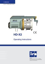
Technical specifications<strong>Chrono</strong>-<strong>X3</strong> 3Technical specificationsMax 1800 m/min8.6 kgMin 5° C - Max 40° CRH max 85 %Sound pressure Lpa 74 dB (A), Sound power Lwa 88 dB (A)Ø max 5 mmInput air pressure 5,5 - 7 barPower Supply/ InterfaceMax yarn separation 4 mm200 - 575V 400VAMax T 10AFuseInterface3,3 kgPower Supply via Loom1,4 kgExtension Interface9Power via Power Supply/ Interface connected to extension plug<strong>AB</strong>CD1,4 kgRef. No. 24-893J-2001-02/1232NoteSubject to technical modifications.
Mains connection<strong>Chrono</strong>-<strong>X3</strong> 4warning!Turn off the main switch before any work is carried out on the electrical circuit.NOTECondensation can form on the weft feeder when it is moved from the cold environment of the warehouseto the warmer environment of the loom room. Make sure that the feeder is dry before switching it on.Take the Voltage Supply Box out of the packing. Openthe cover and connect the three-phase power cord.(4-wires cable). Make sure that the earthconnection is properly made The section of each wirecannot be less than 1,5 mm 2 .Min 4x1,5 mm 2The power supply to the feeder must not bedisrupted when the weaving machine stops.Mains supplyMain switchEmergency stopVariations in main voltage.Ref. No. 24-893J-2001-02/1232Nominal Voltage Frequence200V - 346V 180V - 380V 50/ 60 Hz380V - 400V 342V - 440V 50/ 60 Hz415V - 575V 374V - 632V 50/ 60 Hz
Operating diagram<strong>Chrono</strong>-<strong>X3</strong> 5Motor control unit and fuse panelMotorAccessoriesMotor control unitPower Supply/InterfaceExtension InterfaceFeeder 1- 8Feeder 9-12Accessories A-DRef. No. 24-893J-2001-02/1232PowerLoom communication cable
Connections interface<strong>Chrono</strong>-<strong>X3</strong> 7InterfacePower supplied via loomCAN - INTERFACESTAND ALONE - INTERFACEJ8J1J2J2J1FB2FB1FB2FB1FusesFusesFB1T 3,15 AFB1T 3,15 AFB2T 5 AFB2T 5 AStop relay jumpersStop relay jumpersJ1 + J2Open = Communication bus not terminatedClosed = Communication bus terminatedJ1 + J2Open = Communication bus not terminatedClosed = Communication bus terminatedJ8Normally openRef. No. 24-893J-2001-02/1232
Jumper/ speed settings<strong>Chrono</strong>-<strong>X3</strong> 9Motor circuit board jumpersThe feeder is equipped with jumpers on the motor circuit board that adapt the feeders operation to thecharacteristics of the weaving process. (Weaving machine settings have priority over jumper settings).J1J2J3J4Opto sensorsMech. sensorsJ1Yarn store sensor sensitivity- LOWJ1Yarn break sensor filtering-RIGID YARNSJ1Yarn store sensor sensitivity- AUTOJ1Yarn break sensor filtering- NORMALJ2Integrated yarn break sensor- DIS<strong>AB</strong>LEJ2Integrated yarn break sensor- DIS<strong>AB</strong>LEJ2Integrated yarn break sensor- EN<strong>AB</strong>LEJ2Integrated yarn break sensor- EN<strong>AB</strong>LEJ3Winding disc positioning-DIS<strong>AB</strong>LE (one way bearing)J3Winding disc positioning- DIS<strong>AB</strong>LE(one way bearing)J3Winding disc positioning- EN<strong>AB</strong>LEJ3Winding disc positioning- EN<strong>AB</strong>LEJ4Pattern in advance- DIS<strong>AB</strong>LEDJ4Pattern in advance- DIS<strong>AB</strong>LEDJ4Pattern in advance- EN<strong>AB</strong>LEDJ4Pattern in advance- EN<strong>AB</strong>LEDMaximum speed mech. sensorRef. No. 24-893J-2001-02/1232To set the maximum speed rotate the disc to the appropriateposition.1 = 1500 m/min2 = 1200 m/min3 = 800 m/min4 = 500 m/min12 34
Main parts<strong>Chrono</strong>-<strong>X3</strong> 10Mech. sensorWinding discYarn break detectorYarn store sensorsOpto sensorBrush ringholderadjustmentTension ring quick-releaseMountSpool bodyCATON/OFF SwitchIndicatorAdjustmentMax speed(Mech. sensor only)TECRef. No. 24-893J-2001-02/1232S/Z SwitchThreading
Yarn control<strong>Chrono</strong>-<strong>X3</strong> 11When weaving certain types of yarn and under special weaving conditions it may be necessary to use yarn controlelements in positions 1 and 3. The tables below and on the following page describe suitable combinations.Yarn control element positions231Yarn control element – type and positionELEMENT TYPE Position ELEMENT TYPE PositionA1G(E-flex)2B13HBrush2C1J(CAT)3D1K3Ref. No. 24-893J-2001-02/1232ELamella2
Pneumatic threading<strong>Chrono</strong>-<strong>X3</strong> 14FULL THREADING, automatic slide shift• Restart the feeder to automatically position thewinding disc (empty spool body)• Insert the yarn into the eyelet and press both buttons,whilst lightly holding the yarn.FULL THREADING, Manual slide shift• Restart the feeder to automatically position thewinding disc (empty spool body)• Open the brush holder, see page 17.• Insert the yarn into the eyelet and press both thebuttons, whilst lightly holding the yarn.Half THREADING, backInsert the yarn into the eyelet and press the right button,whilst lightly holding the yarn.Half THREADING, frontInsert the yarn into the eyelet and press the left button,whilst lightly holding the yarn.Ref. No. 24-893J-2001-02/1232
Manual threading<strong>Chrono</strong>-<strong>X3</strong> 15WITHOUT CAT• Switch off the feeder.• Align the winding disc eyelet (1).• Open the brush holder (see page 17).• Thread the needle all the way through thefeeder and output eyelet.• Pull the yarn through.• Restart the feeder.1WITH CAT• Switch off the feeder.• Align the winding disc eyelet.• Thread the needle through the feeder andballoon control brush.• Start the feeder and fill the yarn store.• Insert the threading needle into the CAT (2) as faras possible.• Pulling the yarn (3) will cause it to wrap around thethreading needle.• When the threading needle is pulled out (4) the yarnwill follow.32WARNINGWhen using a threading needle, care must be takento avoid damaging the Flex Brake. Ensure thatthe flex holder is in the forward position beforethreading.4Ref. No. 24-893J-2001-02/1232
TEC Tensioner<strong>Chrono</strong>-<strong>X3</strong> 16THREADING THE TEC• Open the cover (1)• Insert a threading needle (2)• Pull on the yarn (3). The yarn will wrapitself around the needle• Pull out the needle (4)• Close the cover (5)12354Position ARecommended when using the TEC togetherwith a 30° FlexBrake.<strong>AB</strong>Position BRecommended when using the TEC togetherwith a Brush Ring or a 42° Flexbrake.CHANGING THE TENSION STRIP• Open the cover (1)• Remove the cap (6)• Tilt the strip to remove (7)• Tilt the new strip forwards to insert• Close the cover (5)67Ref. No. 24-893J-2001-02/1232Light stripStandard stripHeavy duty strip
Brush/ M-flex<strong>Chrono</strong>-<strong>X3</strong> 17Brush mountingRotating the slide shift lever (1) will detach the brushholder (2) from the spool body.12Ensure that the brush ring is correctly positioned (3).3M-flex mountingRotating the slide shift lever (1) will detach the M-flex (2)from the spool body.12Ensure that the M-flex is correctly positioned (3).Ref. No. 24-893J-2001-02/12323
Balloon adjustment<strong>Chrono</strong>-<strong>X3</strong> 18Balloon control adjustment.NOTEExcessive brush tension will cause abnormal wear.Nose PositionMounting position of the nose: 42°or 30°42°30°Ref. No. 24-893J-2001-02/1232
Cat adjustment<strong>Chrono</strong>-<strong>X3</strong> 19Control input yarn tension to the CAT.NOTEThe brush ring shall only be used for ballooncontrol.Adjustment of the output tension.Ref. No. 24-893J-2001-02/1232
Sensor adjustment<strong>Chrono</strong>-<strong>X3</strong> 20Opto sensorCertain yarn types may stick to, or leavedeposits on, the sensor mirror.In such cases the clearance between theyarn and the mirror can be increased.Adjust the clearance by rotating the mirror180 degrees.Normal PositionIncreased clearanceCertain yarns may cause excessive vibrationof the sensors. This can be remediedby increasing the damper pressure.Mech. sensorYarn break sensorYarn store sensors+ –+ –Ref. No. 24-893J-2001-02/1232
Maintenance<strong>Chrono</strong>-<strong>X3</strong> 21CleaningIt is recommended to carry out a periodicalcleaning of any lint or dust accumulation onthe feeder or the control box.min 20 cmlubricationThe unit requires no extra lubrication.ConnectionsMain switchWarningAlways turn off the main switch or isolate thepower supply and disconnect the air supply beforeconnecting or disconnecting the feeder, the controlboard or any of the circuit boards.<strong>IRO</strong>/ ROJ Tool kitIt is recommended to use <strong>IRO</strong> tool kit, with specialisedtools, to ensure easy and correct disassembly/ assemblyof <strong>IRO</strong> feeders during maintenance work.Please contact your local <strong>IRO</strong> service station for furtherinformation.Ref. No. 24-893J-2001-02/1232