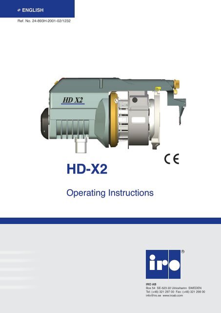
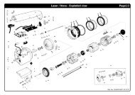
HD-X2 - IRO AB
HD-X2 - IRO AB
HD-X2 - IRO AB
- No tags were found...
Create successful ePaper yourself
Turn your PDF publications into a flip-book with our unique Google optimized e-Paper software.
Contents<strong>HD</strong>-<strong>X2</strong> 1Contents........................................................................................................................1Safety............................................................................................................................2Technical specifications.................................................................................................3Mains connection..........................................................................................................4Operating diagram.........................................................................................................5Operating diagram.........................................................................................................6Connections Power supply/ interface............................................................................7Connections heavy duty power supply..........................................................................8Connections heavy duty power supply can.................................................................9Installation...................................................................................................................10Voltage supply box / Jumper settings..........................................................................11Main parts....................................................................................................................12Speed settings.............................................................................................................13S/Z adjustment............................................................................................................14Threading....................................................................................................................15Sensors settings..........................................................................................................16Funnel.........................................................................................................................17Brush/flex brake..........................................................................................................18Balloon adjustment......................................................................................................19Maintenance................................................................................................................20Assembly instructions..................................................................................................21Fault finding.................................................................................................................22Declaration of conformity.............................................................................................23This section contains important safety information. Read the manual carefully before installing,using or maintaining the feeder.WARNINGindicates a possible dangerous situation which couldresult in serious injury or damage to the unit.CAUTIONindicates a possible dangerous situation whichcould result in minor/moderate injury or damageto the unit.NOTEused in order to draw attention to important information,which facilitates operation or handling.Ref. No. 24-893H-2001-02/1232ORIGINAL LANGUAGE INSTRUCTIONIro ab reserve the right to change the contents of the user’s guideand technical specifications without prior notification.
Safety<strong>HD</strong>-<strong>X2</strong> 2WARNING!• The power supply must be switched off at the mainsbefore any work is carried out on the feeder, thetransformer or any other electrical components. Thefeeder and the transformer cabinet must be fullyassembled before the power supply is connected.• The weft feeder ON/OFF-switch does not cut off themain power supply. Turn off the main switch beforeany work is carried out on the electrical circuit.• The feeder and transformer contain electrical componentsthat retain an electric current up to threeminutes after disconnectionCAUTION!• Caution must be taken in the close vicinity of thefeeder as it contains moving parts that can causeinjuries and, in normal operation, starts without priorwarning.• To comply with c.E. Regulations only replacementparts approved by <strong>IRO</strong> <strong>AB</strong> may be used.• The feeder is an industrial product and therefore notapproved to use household environments /in residentialareas.• All work on electrical components must be carriedout by a qualified electrician.• This product is not intended for use in potentiallyexplosive atmospheres or in zones classified accordingto the european directive 94/9/ec. Please contactiro ab if products for use in a potentially explosiveatmosphere are required.• Always turn off the main switch or isolate thepower supply and disconnect the air supply beforeconnecting or disconnecting the feeder, the controlboard or any of the circuit boards• Routine checks for damaged or worn parts must bemade before operating this equipment. Any part thatis worn or damaged should be properly repaired orreplaced by authorized personnel. To avoid risk ofinjury DO NOT operate this equipment if any componentdoes not appear to be functioning correctly.NOTE• To ensure the selection of the most suitable feeder and associated accessories, it is recommended makingweaving tests with the intended yarns.• Please dispose of obsolete or unwanted equipment responsibly, taking into consideration any local regulationsregarding the disposal and / or recycling of materials that are applicable.Ref. No. 24-893H-2001-02/1232
Voltage supply box / Jumper settings<strong>HD</strong>-<strong>X2</strong> 11VOLTAGE SUPPLY BOXThe <strong>HD</strong> <strong>X2</strong> feeder is compatible with the standard Lineof <strong>X2</strong> voltage supply boxes (maximum 4 feeders foreach control box).WARNINGFor applications with multiple insertions (two ormore yarns together at the same time), it is necessaryto use an <strong>X2</strong> control box suitable for higherpower consumption.min 20 cmFix the voltage supply box to the stand by means of theproper brackets.NoteMinimum distance from the box to the floor must be20 cmjumper settingsThe feeder is equipped with jumpers on the motorcircuit board that adapt the feeders operation to thecharacteristics of the weaving process. (Weavingmachine settings have priority over jumper settings).NoteOnly for installations on CAN looms, if for testreasons it is needed to run the feeder withoutPattern in advance and Start/Stop informationfrom the loom, set Jumper J3 to closed(disabled).NOTEWhenever the electronic board or the sensorsboard are replaced, it is necessary to carry outthe “Automatic sensor calibration procedure”.J3J3J4J4Pattern in advance- DIS<strong>AB</strong>LEDPattern in advance- EN<strong>AB</strong>LEDWinding disc positioning- DIS<strong>AB</strong>LEDWinding disc positioning- EN<strong>AB</strong>LEDRef. No. 24-893H-2001-02/1232
Main parts<strong>HD</strong>-<strong>X2</strong> 12Yarn break detectorWinding discYarn store sensorsBrush ring holderadjustmentTension ringquick-releaseFunnelCONESpool bodyIndicatorMax speedON/OFF SwitchBRUSH RINGThreadingPP2Ref. No. 24-893H-2001-02/1232S/Z Switch
Speed settings<strong>HD</strong>-<strong>X2</strong> 13NoteNormally the switch should be left at posistion1 since the feeder automatically calculates thespeed according to yarn consumption. However,with very low speeds or wide looms, it could behelpful to reduce the maximum speed in order toavoid unnecessary acceleration12 34To set the maximum speed rotate the disc to theappropriate position.Mechanical sensors, STAND-ALONE1 = 1400 m/min2 = 1200 m/min3 = 800 m/min4 = 500 m/minMechanical sensors, CAN1 = 1600 m/min2 = 1200 m/min3 = 800 m/min4 = 500 m/minRef. No. 24-893H-2001-02/1232
S/Z adjustment<strong>HD</strong>-<strong>X2</strong> 14With standard ball bearing1. Switch off the feeder.2. Grip the winding disc (1) and, whilst pressing theorange button on the front of the spool body (2),rotate the disc until the button is felt to locate. Aligningthe mark on the winding disc with the line onthe motor house gives the zero separation position.1To adjust, press in the button and revolve the windingdisc in the appropriate direction.21Set the direction of rotation with the switch.(The feeder is deactivated in the standby position (0))0The separation must be distinct, but notexcessive.Ref. No. 24-893H-2001-02/1232
Sensors settings<strong>HD</strong>-<strong>X2</strong> 16The mechanical sensors are placed on the fixed part ofthe spool body.The sensor (1) controls MAX reserve level, and the sensor(2) controls MIN reserve level.1The force needed to press down the sensors is controlledby a spring, and it is adjustable with screw (3). Turnthe screw (3) anti-clockwise to increase the sensorstrength, turn it clockwise to reduce it.32Automatic calibration of the sensorsNoteBefore starting the automatic sensors calibration,check the following:• Remove all yarn from the feeder• The spool body must be in correct position.• The sensors must be free to correctly move up anddown.• The sensors ring must be correctly fixed.1. Switch OFF the feeder.2. Disable the TFE7 by moving the switch (4) upwards.The LED of TFE7 must be steady-ON in red color.(5)3. Switch ON the feeder and let it turn without weft for atleast 50 revolutions, until the winding disk stops.(feeder red light steady ON).4. Switch OFF the feeder, and enable the TFE7 by movingthe switch down5. Thread the yarn through the feeder (see page 15)6. Switch ON the feeder and load a new weft reserve.54LED (5)When disabled, the LED (5) is steady RED ON.When enabled, the LED (4) is GREEN only when theyarn is creating signal, other way it is OFF.Ref. No. 24-893H-2001-02/1232
Funnel<strong>HD</strong>-<strong>X2</strong> 17Suitable for heavy yarns which create large balloons.Suggested for polypropylene flat tape on projectilelooms.NoteThere is no braking function on the yarn when thefunnel is installed since it is used only to controlthe balloon effect during the yarn taking-off.11Funnel fitting1. Slightly screw the three nuts (1) with the screws.2. Slide the fixing screws into the guides of the Sensorholderring.3. Push the funnel completely against the Sensor-holderring. (2)4. Position the screws in the proper slots, then fix them withthe nuts. (3)1332Ref. No. 24-893H-2001-02/12323
Balloon adjustment<strong>HD</strong>-<strong>X2</strong> 19Balloon control adjustment.NOTEExcessive brush tension will cause abnormal wear.Nose PositionMounting position of the nose: 30°, 42° or 55°(55° = standard position)55° 42° 30°Ref. No. 24-893H-2001-02/1232
Maintenance<strong>HD</strong>-<strong>X2</strong> 20CleaningIt is recommended to carry out a periodicalcleaning of any lint or dust accumulation onthe feeder or the control box.min 20 cmlubricationThe unit requires no extra lubrication.ConnectionsMain switchWarningAlways turn off the main switch or isolate thepower supply and disconnect the air supply beforeconnecting or disconnecting the feeder, the controlboard or any of the circuit boards.<strong>IRO</strong>/ ROJ Tool kitIt is recommended to use <strong>IRO</strong> tool kit, with specialisedtools, to ensure easy and correct disassembly/ assemblyof <strong>IRO</strong> feeders during maintenance work.Please contact your local <strong>IRO</strong> service station for furtherinformation.Ref. No. 24-893H-2001-02/1232
Assembly instructions<strong>HD</strong>-<strong>X2</strong> 21After disassembling, it is necessary to install the spoolbodypart by part to avoid damaging the parts.Secure the bellow properly with plastic straps (1).11Be sure that the carrier pin fits into the keygroove in themotor shaft (2).2Insert the two screws for the rubber belly (3) and besure they are properly tightened with the correct key.(Torx T10)333Turn the winding disc (4) when holding the centre nut (5)to get the balance weight in position. When correct, thedisc can easily be moved 180° only.544Ref. No. 24-893H-2001-02/1232Install the centre screw, outer rubber belly, spoolbodyand cover. Set the yarn separation in a suitable positionto be sure it is correctly assembled.
Fault finding<strong>HD</strong>-<strong>X2</strong> 22FaultCheck in the following orderFeeder will not start 1 - 2 - 3 - 5 - 6 - 7 - 8 - 24 - 25 - 26Feeder will not stop 9 - 5 - 24 - 25Low or empty yarn store 17 - 3 - 5 - 8 - 24 - 25 - 27 - 26Input yarn breaks frequently 22 - 10 - 18Output yarn breaks frequently 11 - 20 - 12 - 19 - 23Fuses blow repeatedly 25 - 28Feeder warning light flashes slowly 30Feeder warning light flashes rapidly 3 - 8 - 25 - 26 - 27Feeder warning light continously on 29No Possible causes RemediesSeepage1. Incorrect S/Z switch position Set the S/Z switch in appropriate position 142. Incorrect spoolbody position Ensure the sensor unit is positioned upwards 163. Winding disc jammed Free and clean the winding disc 205. Sensor arms jammed Free the arms and clean the sensing unit 206. Faulty cable connections Check and rectify 4-97. Fuses blown Replace the relevant fuse 6-98. Mains supply / primary voltage fault Check the mains supply and connections 4-99. Insufficient input tension Increase the input tension -10. Excessive input tension Reduce the input tension -11. Insufficient balloon control Increase the balloon control 1912. Excessive output tension Reduce the output tension 1917. Insufficient max speed setting Increase the max speed setting 1318. Excessive max speed setting Reduce the max speed setting 1319. Insufficient yarn store See “low or empty yarn store” under “fault” -20. Damaged balloon control Repair/replace all defective parts 1922. Misalignment between the bobbin and Realign the bobbin/feeder -the feeder23. Misalignment between the feeder and Realign the feeder/machine -the machine24. Defect sensor board Replace the sensor board 1225. Defective motor circuit board Replace the relevant circuit board 526. Defective fuse panel Replace the relevant fuse panel 6-927. Defective control box interface Replace the relevant interface 6-928. Defective feeder connection cable Replace the relevant connection cable -29. Yarn break Rethread the feeder 1530. Sensor out of calibration Execute automatic sensor calibration 16Ref. No. 24-893H-2001-02/1232
Declaration of conformity<strong>HD</strong>-<strong>X2</strong> 23<strong>IRO</strong> <strong>AB</strong>Box 54SE-523 22 UlricehamnEC DECLARATION OF CONFORMITYEG-KONFORMITÄTSERKLÄRUNGDECLARATION CE DE CONFORMITEDICHIARAZIONE CE DI CONFORMITA’DECLARACIÓN DE CONFORMIDAD CEDECLARAÇÃO CE DE CONFORMIDADE CEGuarantee that machine type:.........................Versichert dass der Maschinentyp:.................Guarantie pour machine type:.........................Garantische che il tipo di macchina:................Garantia que é o tipo de màquina:..................Garantiza de que os tipos de màquinas:.........<strong>HD</strong>-<strong>X2</strong>Is manufactured in comformity with the provisions of the following EC directives and applicable amendments:Ist gemäss der folgenden für Maschinen geltenden EG-Richtlinjen hergestellt worden (damit auch allezusätzliche Änderungen)Est fabriqué en conformité aux dispositions des directives CE suivantes (y compris tous les amendements):E´costruito in conformità a quanto previsto dalle seguenti direttive UE e successive modifiche:Està fabricado conforme con las disposiciones de las debajo mencionadas directivas CE (y sucesivasmodificaciones):Està fabricado em conformidade como estabelecido nas seguintes directivas CE (incluido altarações):Safety of machinery 98/ 37/ EEC EN ISO 111 11-1Low voltage equipment 2006/ 95/ EC EN ISO 111 11-1Electromagnetic compatility 2004/ 108/ EC EN ISO 111 11-1Ref. No. 24-893H-2001-02/1232Pär Josefsson, Manager Product and Development department, 2007-12-01


