Mate users manual
Mate users manual
Mate users manual
- No tags were found...

Create successful ePaper yourself
Turn your PDF publications into a flip-book with our unique Google optimized e-Paper software.
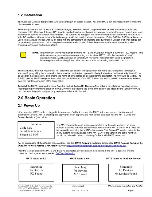
1.2 InstallationThe OutBack MATE is designed for surface mounting in an Indoor location. Keep the MATE out of direct sunlight to make thedisplay easier to view.The cabling from the MATE to the FX inverter/charger, MX60 PV MPPT charge controller or HUB is standard CAT5 typecomputer cable. Standard Ethernet CAT5 cable, can be found at any home improvement or computer store. Consult your localinspector for specific installation requirements. The current and voltage in the communication cable is limited to less than 30volts DC and is considered to be a “limited energy circuit”. No conduit should be required. Either CAT5 or CAT5e cable can beused. The MATE is shipped with 50’ of cable with the correct RJ45 connectors already installed. Longer or shorter cables canbe purchased pre-made or custom length cable can be made on site. Follow the cable manufactures’ instructions whenchoosing connectors and crimping tools.NOTE: The maximum tested cable length from the MATE to an OutBack product is 1000 feet (300 meters). Thisdistance can vary depending on cable routing and location. MATE cable that is run in a ‘noisy’environment (ex. MATE cable run in conduit with AC wiring) will suffer from signal degradation,impacting the maximum length the cable can be run without incurring transmission errors.The MATE should be wall mounted at just below the eye level of the typical user. No wiring box is required, although astandard 2 gang wiring box mounted in the horizontal position (as opposed to the typical vertical position of a light switch) canbe used for the cable entry. By bending the wiring at a 90 degree angle just after the connector, no wiring will be visible. TheRS-232 port for the PC computer is accessible from the bottom of the MATE when it is wall mounted. It also can be removedfrom the wall for connection of the serial cable.To install the MATE, unsnap the cover from the back of the MATE. There are four holes in this plate for mounting screws.After installing the mounting plate on the wall, connect the cable to the jack on the back of the circuit board. Snap the MATEonto the mounting plate and push any excess cable back into the wall.2.0 Basic Operation2.1 Power UpA soon as the MATE cable is plugged into a powered OutBack product, the MATE will power-up and display severalinformation screens. After a greeting and copyright screen appears, the next screen displayed has the MATE Code andScreen Revisions (see below).VersionCode a.aaSerial #xxxxxxxxScreen EE b.bbThe MATE’s operation and features are dictated by the code version. The serialnumber displayed matches the bar coded sticker on the MATE’s main PCB. This canbe viewed by removing the MATE’s back cover. The Screen EE version refers to themenu system currently loaded in the MATE. All of the version and serial numbersshould be referred to when contacting OutBack with MATE questions.For an explanation of the differing code versions, see the MATE firmware revisions topic under MATE Release Notes on theOutBack Power Systems User Forum found at: http://www.outbackpower.com/cgi-bin/Forum/ultimatebb.cgi .After the Version screen the MATE will display a connected devices screen (see below). If the MATE does not find theconnected device, refer to the section 7.0 Troubleshooting.MATE found an FX MATE found a MX MATE found no OutBack ProductSearchingfor DevicesFX FoundSearchingfor DevicesMX FoundSearchingfor DevicesNo Devices FoundCopyright 2003 © OutBack Power Systems, Inc User Manual . MATE System Controller and Display19009 62 nd Ave NE, Arlington WA 98223 USATel 360 435 6030 Fax 360 435 6019 Rev 2.30 03/31/04 Page 5