Miller AL4 Series
Miller AL4 Series
Miller AL4 Series
- No tags were found...

Create successful ePaper yourself
Turn your PDF publications into a flip-book with our unique Google optimized e-Paper software.
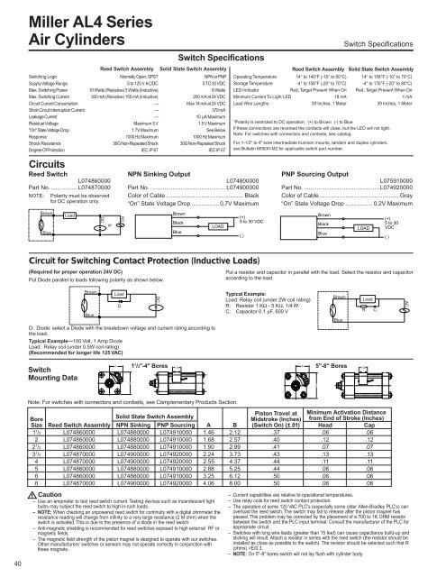
<strong>Miller</strong> <strong>AL4</strong> <strong>Series</strong>Air CylindersBrownBlueLoadReed Switch AssemblyDCorACSwitch SpecificationsSolid State Switch AssemblySwitching Logic Normally Open, SPST NPN or PNPSupply Voltage Range 5 to 125 V AC/DC 5 TO 30 VDCMax. Switching Power 10 Watts (Resistive) 5 Watts (Inductive) 6 WattsMax. Switching Current 300 mA (Resistive) 150 mA (Inductive) 200 mA at 24 VDCCircuit Current Consumption — Max 14 mA at 24 VDCShort Circuit Interruption Current — 370 mALeakage Current — 10 µA MaximumResidual Voltage Maximum 3 V 1.5 V Maximum"On" State Voltage Drop 1.7V Maximum See BelowResponse 1000 Hz Maximum 1000 Hz MaximumShock Resistance 30G Non-Repeated Shock 30G Non-Repeated ShockDegree Of Protection IEC IP 67 IEC IP 67CircuitsReed SwitchL074860000Part No. ................ L074870000NOTE:Polarity must be observedfor DC operation only.NPN Sinking OutputL074800000Part No. ............................................... L074900000Color of Cable ................................................ Black“On” State Voltage Drop ................. 0.7V MaximumBrownBlackBlueLOADSwitch SpecificationsReed Switch Assembly Solid State Switch AssemblyOperating Temperature 14° to 140°F (-10° to 60°C) 14° to 158°F (-10° to 70°C)Storage Temperature -4° to 158°F (-20° to 70°C) -4° to 176°F (-20° to 80°C)LED Indicator Red, Target Present When On Red, Target Present When OnMinimum Current To Light LED 18 mA 1 mALead Wire Lengths 39 Inches, 1 Meter 39 Inches, 1 Meter1 Polarity is restricted to DC operation: (+) to Brown (-) to BlueIf these connections are reversed the contacts will close, but the LED will not light.Note: For switches with connectors and cordsets, see catalog.For 1-1/2" to 4" bore intermediate trunnion mounts, tandem and duplex cylinders,see Bulletin M0830-M2 for applicable switch part number.(+)5 to 30 VDC()PNP Sourcing OutputL075910000Part No. ............................................... L074920000Color of Cable ................................................. Gray“On” State Voltage Drop ................. 0.2V MaximumBrownBlackBlueLOAD(+)5 to 30VDC()Circuit for Switching Contact Protection (Inductive Loads)(Required for proper operation 24V DC)Put Diode parallel to loads following polarity as shown below.Put a resistor and capacitor in parallel with the load. Select the resistor and capacitoraccording to the load.BrownBlueLoadDD: Diode: select a Diode with the breakdown voltage and current rating according tothe load.Typical Example—100 Volt, 1 Amp DiodeLoad: Relay coil (under 0.5W coil rating)(Recommended for longer life 125 VAC)DCTypical Example:BrownLoad: Relay coil (under 2W coil rating)LoadR: Resistor 1 KΩ - 5 KΩ, 1/4 WC: Capacitor 0.1 µF, 600 V R CBlueACSwitchMounting DataA1 1 /2"-4" Bores A1.005"-8" BoresBB1.0040Note: For switches with connectors and cordsets, see Complementary Products Section.Piston Travel at Minimum Activation DistanceBoreSolid State Switch AssemblyMidstroke (Inches) from End of Stroke (Inches)Size Reed Switch Assembly NPN Sinking PNP Sourcing A B (Switch On) (±.01) Head Cap1 1 /2 L074860000 L074880000 L074910000 1.46 2.12 .37 .06 .062 L074860000 L074880000 L074910000 1.68 2.57 .40 .12 .122 1 /2 L074860000 L074880000 L074910000 1.90 2.99 .41 .07 .073 1 /4 L074870000 L074900000 L074920000 2.24 3.73 .43 .13 .134 L074870000 L074900000 L074920000 2.55 4.37 .44 .11 .115 L074860000 L074880000 L074910000 2.88 5.25 .44 .06 .066 L074860000 L074880000 L074910000 3.25 6.12 .50 .06 .068 L074870000 L074900000 L074920000 4.06 8.00 .50 .06 .06! Caution– Current capabilities are relative to operational temperatures.– Use an ampmeter to test reed switch current. Testing devices such as incandescent light – Use relay coils for reed switch contact protection.bulbs may subject the reed switch to high in-rush loads.– The operation of some 120 VAC PLC's (especially some older Allen-Bradley PLC's) can– NOTE: When checking an unpowered reed switch for continuity with a digital ohmmeter the overload the reed switch. The switch may fail to release after the piston magnet hasresistance reading will change from infinity to a very large resistance (2 M ohm) when the passed. This problem may be corrected by the placement of a 700 to 1K OHM resistorswitch is activated. This is due to the presence of a diode in the reed switch.between the switch and the PLC input terminal. Consult the manufacturer of the PLC for– Anti-magnetic shielding is recommended for reed switches exposed to high external RF or appropriate circuit.magnetic fields.– Switches with long wire leads (greater than 15 feet) can cause capacitance build-up and– The magnetic field strength of the piston magnet is designed to operate with our switches. sticking will result. Attach a resistor in series with the reed switch (the resistor should beOther manufacturers’ switches or sensors may not operate correctly in conjunction with installed as close as possible to the switch). The resistor should be selected such that Rthese magnets.(ohms) >E/0.3.– NOTE: On 5"-8" bores switch will not lay flush with cylinder body.