Miller AL4 Series
Miller AL4 Series
Miller AL4 Series
- No tags were found...

You also want an ePaper? Increase the reach of your titles
YUMPU automatically turns print PDFs into web optimized ePapers that Google loves.
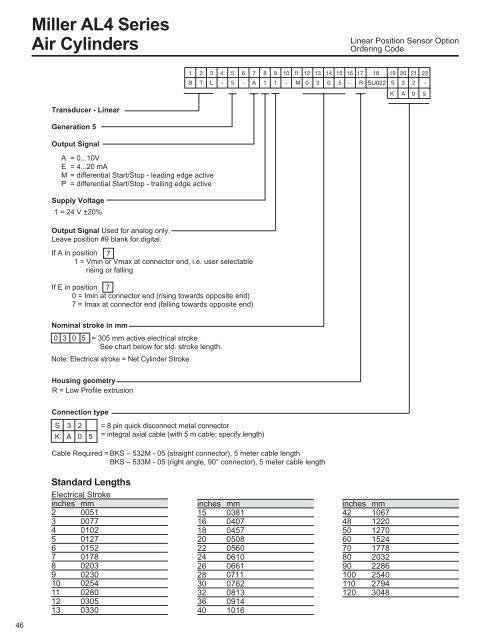
<strong>Miller</strong> <strong>AL4</strong> <strong>Series</strong>Air CylindersLinear Position Sensor OptionOrdering CodeTransducer - LinearGeneration 5Output SignalA = 0...10VE = 4...20 mAM = differential Start/Stop - leading edge activeP = differential Start/Stop - trailing edge activeSupply Voltage1 = 24 V ±20%Output Signal Used for analog only.Leave position #9 blank for digital.If A in position 71 = Vmin or Vmax at connector end, i.e. user selectablerising or fallingIf E in position 70 = Imin at connector end (rising towards opposite end)7 = Imax at connector end (falling towards opposite end)Nominal stroke in mm0 3 0 5 = 305 mm active electrical stroke.See chart below for std. stroke length.Note: Electrical stroke = Net Cylinder StrokeHousing geometryR = Low Profile extrusionConnection typeS 3 2K A 0 5= 8 pin quick disconnect metal connector= integral axial cable (with 5 m cable; specify length)Cable Required = BKS – 532M - 05 (straight connector), 5 meter cable lengthBKS – 533M - 05 (right angle, 90° connector), 5 meter cable lengthStandard LengthsElectrical Strokeinches mm2 00513 00774 01025 01276 01527 01788 02039 023010 025411 028012 030513 0330inches mm15 038116 040718 045720 050822 056024 061026 066128 071130 076232 081336 091440 1016inches mm42 106748 122050 127060 152470 177880 203290 2286100 2540110 2794120 304846