Miller AL4 Series
Miller AL4 Series
Miller AL4 Series
- No tags were found...

Create successful ePaper yourself
Turn your PDF publications into a flip-book with our unique Google optimized e-Paper software.
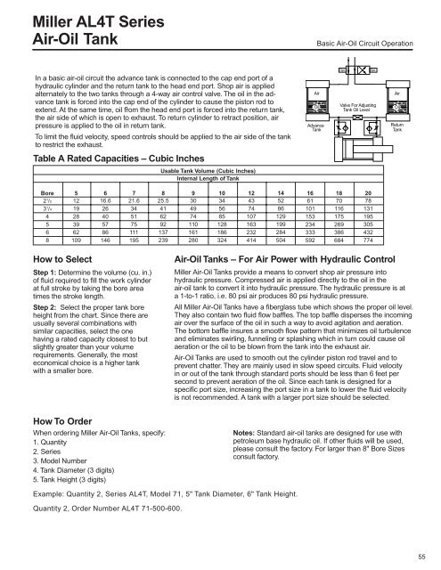
<strong>Miller</strong> <strong>AL4</strong>T <strong>Series</strong>Air-Oil TankBasic Air-Oil Circuit OperationIn a basic air-oil circuit the advance tank is connected to the cap end port of ahydraulic cylinder and the return tank to the head end port. Shop air is appliedalternately to the two tanks through a 4-way air control valve. The oil in the advancetank is forced into the cap end of the cylinder to cause the piston rod toextend. At the same time, oil from the head end port is forced into the return tank,the air side of which is open to exhaust. To return cylinder to retract position, airpressure is applied to the oil in return tank.To limit the fluid velocity, speed controls should be applied to the air side of the tankto restrict the exhaust.AirOilAdvanceTankValve For AdjustingTank Oil LevelAirOilReturnTankTable A Rated Capacities – Cubic InchesUsable Tank Volume (Cubic Inches)Internal Length of TankBore2 1 /23 1 /4456851219283962109616.626405786146721.6345175111195825.5416292137239930497411016128010345685128186324124374107163232414145286129199284504166110115323433359218701161752693866842078131195305432774How to SelectStep 1: Determine the volume (cu. in.)of fluid required to fill the work cylinderat full stroke by taking the bore areatimes the stroke length.Step 2: Select the proper tank boreheight from the chart. Since there areusually several combinations withsimilar capacities, select the onehaving a rated capacity closest to butslightly greater than your volumerequirements. Generally, the mosteconomical choice is a higher tankwith a smaller bore.How To OrderWhen ordering <strong>Miller</strong> Air-Oil Tanks, specify:1. Quantity2. <strong>Series</strong>3. Model Number4. Tank Diameter (3 digits)5. Tank Height (3 digits)Air-Oil Tanks – For Air Power with Hydraulic Control<strong>Miller</strong> Air-Oil Tanks provide a means to convert shop air pressure intohydraulic pressure. Compressed air is applied directly to the oil in theair-oil tank to convert it into hydraulic pressure. The hydraulic pressure is ata 1-to-1 ratio, i.e. 80 psi air produces 80 psi hydraulic pressure.All <strong>Miller</strong> Air-Oil Tanks have a fiberglass tube which shows the proper oil level.They also contain two fluid flow baffles. The top baffle disperses the incomingair over the surface of the oil in such a way to avoid agitation and aeration.The bottom baffle insures a smooth flow pattern that minimizes oil turbulenceand eliminates swirling, funneling or splashing which in turn could cause oilaeration or the oil to be blown from the tank into the exhaust air.Air-Oil Tanks are used to smooth out the cylinder piston rod travel and toprevent chatter. They are mainly used in slow speed circuits. Fluid velocityin or out of the tank through standard ports should be less than 6 feet persecond to prevent aeration of the oil. Since each tank is designed for aspecific port size, increasing the port size in a tank to lower the fluid velocityis not recommended. A tank with a larger port size should be selected.Notes: Standard air-oil tanks are designed for use withpetroleum base hydraulic oil. If other fluids will be used,please consult the factory. For larger than 8" Bore Sizesconsult factory.Example: Quantity 2, <strong>Series</strong> <strong>AL4</strong>T, Model 71, 5" Tank Diameter, 6" Tank Height.Quantity 2, Order Number <strong>AL4</strong>T 71-500-600.55