EMI Catalog - Spectrum Control
EMI Catalog - Spectrum Control
EMI Catalog - Spectrum Control
- No tags were found...

Create successful ePaper yourself
Turn your PDF publications into a flip-book with our unique Google optimized e-Paper software.
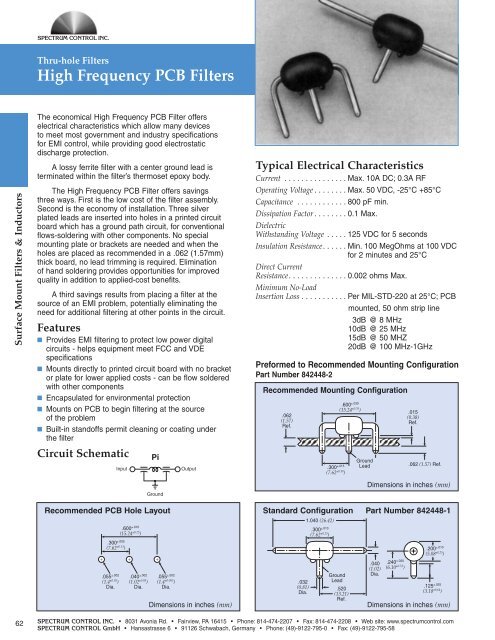
Thru-hole FiltersHigh Frequency PCB FiltersSurface Mount Filters & InductorsThe economical High Frequency PCB Filter offerselectrical characteristics which allow many devicesto meet most government and industry specificationsfor <strong>EMI</strong> control, while providing good electrostaticdischarge protection.A lossy ferrite filter with a center ground lead isterminated within the filter’s thermoset epoxy body.The High Frequency PCB Filter offers savingsthree ways. First is the low cost of the filter assembly.Second is the economy of installation. Three silverplated leads are inserted into holes in a printed circuitboard which has a ground path circuit, for conventionalflows-soldering with other components. No specialmounting plate or brackets are needed and when theholes are placed as recommended in a .062 (1.57mm)thick board, no lead trimming is required. Eliminationof hand soldering provides opportunities for improvedquality in addition to applied-cost benefits.A third savings results from placing a filter at thesource of an <strong>EMI</strong> problem, potentially eliminating theneed for additional filtering at other points in the circuit.Features■ Provides <strong>EMI</strong> filtering to protect low power digitalcircuits - helps equipment meet FCC and VDEspecifications■ Mounts directly to printed circuit board with no bracketor plate for lower applied costs - can be flow solderedwith other components■ Encapsulated for environmental protection■ Mounts on PCB to begin filtering at the sourceof the problem■ Built-in standoffs permit cleaning or coating underthe filterCircuit SchematicInputPiGroundOutputTypical Electrical CharacteristicsCurrent . . . . . . . . . . . . . . . Max. 10A DC; 0.3A RFOperating Voltage . . . . . . . . Max. 50 VDC, -25°C +85°CCapacitance . . . . . . . . . . . . 800 pF min.Dissipation Factor . . . . . . . . 0.1 Max.DielectricWithstanding Voltage . . . . . 125 VDC for 5 secondsInsulation Resistance. . . . . . Min. 100 MegOhms at 100 VDC. . . . . . . . . . . . . . . . . . . . . for 2 minutes and 25°CDirect CurrentResistance. . . . . . . . . . . . . . 0.002 ohms Max.Minimum No-LoadInsertion Loss ...........Per MIL-STD-220 at 25°C; PCBmounted, 50 ohm strip line3dB @ 8 MHz10dB @ 25 MHz15dB @ 50 MHZ20dB @ 100 MHz-1GHzPreformed to Recommended Mounting ConfigurationPart Number 842448-2Recommended Mounting Configuration.062(1.57)Ref..300 ±.015(7.62 ±0.38 ).600 ±.030(15.24 ±0.76 )GroundLead.015(0.38)Ref..062 (1.57) Ref.Dimensions in inches (mm)Recommended PCB Hole Layout.300 ±.005(7.62 ±0.13 )+ + +.055 ±.002(1.4 ±0.05 )Dia..600 ±.010(15.24 ±0.25 ).040 ±.002(1.02 ±0.05 )Dia..055 ±.002(1.4 ±0.005 )Dia.Dimensions in inches (mm)Standard Configuration Part Number 842448-1.032(0.81)Dia.1.040 (26.42).300 ±.010(7.62 ±0.25 )GroundLead.520(13.21)Ref..040(1.02)Dia..240 ±.020(6.10 ±0.51 ).200 ±.010(5.08 ±0.25 ).125 ±.025(3.18 ±0.64 )Dimensions in inches (mm)62SPECTRUM CONTROL INC. • 8031 Avonia Rd. • Fairview, PA 16415 • Phone: 814-474-2207 • Fax: 814-474-2208 • Web site: www.spectrumcontrol.comSPECTRUM CONTROL GmbH • Hansastrasse 6 • 91126 Schwabach, Germany • Phone: (49)-9122-795-0 • Fax: (49)-9122-795-58