Cable Reference Guide - Audio Intervisual Design, Inc.
Cable Reference Guide - Audio Intervisual Design, Inc.
Cable Reference Guide - Audio Intervisual Design, Inc.
- No tags were found...

You also want an ePaper? Increase the reach of your titles
YUMPU automatically turns print PDFs into web optimized ePapers that Google loves.
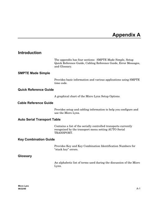
Appendix AIntroductionThe appendix has four sections: SMPTE Made Simple, SetupQuick <strong>Reference</strong> <strong>Guide</strong>, Cabling <strong>Reference</strong> <strong>Guide</strong>, Error Messages,and Glossary.SMPTE Made SimpleProvides basic information and various applications using SMPTEtime code.Quick <strong>Reference</strong> <strong>Guide</strong>A graphical chart of the Micro Lynx Setup Options.<strong>Cable</strong> <strong>Reference</strong> <strong>Guide</strong>Auto Serial Transport TableKey Combination <strong>Guide</strong>GlossaryProvides setup and cabling information to help you configure anduse the Micro Lynx.Contains a list of the serially controlled transports currentlyrecognized by the transport menu setting AUTO SerialTRANSPORT.Provides Key and Key Combination Identification Numbers for“stuck key” errors.An alphabetic list of terms used during the discussion of the MicroLynx.Micro Lynx06/22/00 A-1
AppendixMicro LynxA-2 06/22/00
SMPTE Made SimpleThe Time Code Tutor from TimeLineIntroductionWhen the television broadcast industry moved from film and liveperformance to prerecorded video production, a method was requiredto reliably synchronize and edit the new medium.Historically, film rushes were lined up at the clapper board andrubber stamped with footage numbers, and by default film wasmechanically held in sync by the sprocket holes. Unfortunately,video tape had neither of these attributes. This created a problemof how to get the music, pictures, dialogue, and effects all to beginand run at the same time.The solution was SMPTE time code. SMPTE is a signal with specificaddress information that can be recorded on audio or videotape and used to position them, accurately.Why SMPTE?In 1971, the Society of Motion Picture and Television Engineerschose SMPTE to be the industry standard for synchronization. Itbecame officially known as SMPTE/EBU Time Code when thesociety was joined by its’ overseas counterpart, the EuropeanBroadcast Union (EBU). Since it is quite a mouthful, most peoplejust say SMPTE.What Can You Do with SMPTE?There are hundreds of uses for SMPTE time code in every branchof audio production. They include records, video, film, advertisingand industrials. Let’s start with the how and why of some of themost basic applications.Micro Lynx06/22/00 A-3
AppendixSynchronizing Multiple <strong>Audio</strong> MachinesImagine you are a recording engineer. You’ve just used up all theavailable tracks on your multitrack machine, but your project isnowhere near completion. How are you going to get some extratracks? Use a second multitrack recorder.The question is, “how do you lock the two machines so that themusic plays back in perfect synchronization − first time, everytime.” You could try to hit the Play buttons on both machines atexactly the same moment and then cross your fingers, but theodds of this working even once are very slim.The correct solution is to use SMPTE time code AND a TimeLinesynchronizing system. It works like this: a TimeLine Lynx orMicro Lynx generates time code that is recorded onto the audiotapes. The time code is then used as a common reference point,the “glue” that holds the two machines in sync.On playback, a SMPTE time code reader reads time code from onetape recorder and passes the timing data to a synchronizer connectedto the other tape recorder. Based on this incoming timecode, the synchronizer regulates the playback speed of the slave sothat it always stays in perfect sync with the master.ATR (MASTER)ATR (SLAVE)TIMECODEREADS TIME CODECONTROLS SPEEDLYNX (MASTER)TIMING DATALYNX (SLAVE)SMPTE001AFigure Appendix A-1. Basic SMPTE Time Code SetupThis simple example is the basis for all SMPTE applications. Forinstance, if you are locking to film or video using a digital audioworkstation or a sequencer, you’d just substitute the appropriatecontrolling device to suit the equipment for that application.Micro LynxA-4 06/22/00
SETUPSYS TRAN EVNTLOCKBUSYRECBUSYRECLISTGROUP SELECTLOCK LOCKA B CGRPLOCDEVICE SELECTACGF1BUSYRECF2TCGF3MEMMIDISOLO LOOP RDY TRKSCUEALLSTOPMOTIONRCLCALCULATORSTOASM7 8 9IN OUT DURA4 CUE TC4 5 6SYNCP OFST ERRA1 A2 A31 2 3PRE POST REFVID0 CLR 00TIMEROLLBACKREPLAYREHMACROOPTIONSMIDICOMPUTER KEYBOARDSYSTEMACG VITC M3 DATA VALID DATA VALID DATA VALID DATA VALID ONCAPT=+–SUBFREDITRECINOUTREFLOCK1600 (48K)1920Micro Lynx KeyboardSTATUSSYSTEMMIXEDVIDEOVITCCODEGEN1470 NON+ (44.1K)1764 STD /–DIGITAL AUDIO CLOCK GENERATORLAST NEXT ENTRTRIM JOG SHTLJOG WHEELMicro Lynx System UnitPOWEROPTIONSMIDICOMPUTER KEYBOARDSYSTEMACG VITC M3 DATA VALID DATA VALID DATA VALID DATA VALID ONSETUPSYS TRAN EVNTLOCKBUSYRECLISTGROUP SELECTLOCK LOCKBUSYRECA B CGRPLOCDEVICE SELECTACGF1BUSYRECSOLO LOOP RDY TRKSCUEF2TCGF3MIDIALLSTOPMEMMOTIONRCLASM7 8 9IN OUT DURA4 CUE TC4 5 6SYNCP OFST ERRA1 A2 A31 2 3PRE POST REFVID0 CLR 00TIMEROLLBACKCALCULATORSTOREPLAYREHMACROCAPT=+–SUBFREDITRECINOUTREFLOCK1600 (48K)1920Micro Lynx KeyboardSTATUSSYSTEMMIXEDVIDEOVITCCODEGEN1470 NON+ (44.1K)1764 STD /–DIGITAL AUDIO CLOCK GENERATORLAST NEXT ENTRTRIM JOG SHTLJOG WHEELPOWERAppendixMIDISEQUENCERATRVTRMIDISYSTEM UNITCONTROLTIME CODECONTROLTIME CODESYNCSYNCVSGEXT SYNCTimeLine Micro Lynx System UnitTIME CODEGENERATORRS422TimeLinePOWER SUPPLYKEYBOARD CONTROLLERSMPTE003AFigure Appendix A-3. MIDI Sequencer and Time CodeComplete SystemsThe ultimate SMPTE application is the complete studio system.Just as two devices can be locked to a common time reference, socan a whole roomful: tape machines, consoles, synthesizers,effects processors, and hard disk recorders. With an efficientcontroller like the Micro Lynx Keyboard, all of these differentmachines can be operated as easily as a single set of transportcontrols. Later, we’ll explain how SMPTE is used to build large,multi-machine networks for video editing and music recording.AUTOLOCATORATRATR (DTR)VTRDIGITAL AUDIOWORKSTATIONMIDI OR MACINTERFACECONTROLTIME CODEMECCONTROLTIME CODESYNCCONTROLTIME CODESYNCVSGEXT SYNCTimeLineACGSYSTEM UNITWORD CLOCKTIME CODERS422POWER SUPPLYCONSOLE AUTOMATIONTimeLineCONSOLECOMPUTERKEYBOARD CONTROLLERSMPTE011AFigure Appendix A-4. Complete Studio SystemMicro LynxA-6 06/22/00
AppendixHow Does SMPTE Do It?What You Can Do with a Speed <strong>Reference</strong>If you know precisely where a piece of program is and how fast itis playing, then it is possible to use this information to controlother machines so that they are all in the right place at exactly thesame time. SMPTE does just this, it is an absolute timingreference that indicates both the speed and position of a tape as ittravels across a tape machine transport.Many pre-SMPTE sync codes could only indicate speed. The mostwidely used was control track or pilot tone. Pilot tone is an audiosignal derived from a stable source, historically 60 Hz AC wall current.By reducing the voltage with a suitable transformer, theresultant continuous sine wave could be recorded on tape.Machine speed is normally regulated by monitoring tach pulsesfrom the tape machine’s capstan motor. They indicate how manytimes the capstan revolves in a given time interval, just as anautomobile’s tachometer indicates how fast an engine is turning.When playing a tape with pilot tone back, the sine wave on tape iscompared with a reference sine wave coming from the wall currentor some other guaranteed signal.If the tape slows down, the frequency of the pilot tone, or thenumber of cycles that tick by each second, will decrease. If thetape speeds up, the frequency will increase. A controlling device,tied into the tape machine’s capstan motor, senses the differencebetween the reference tone and the pilot tone on tape; and variesthe speed of the tape machine motor to make the two match upagain.This process of matching tape machine speed to a stable referenceis called resolving. The two sets of sine waves are brought in phasewith one another, so they match up perfectly, peak for peak, troughfor trough. Which is why this is sometimes called phase locked.IN PHASE60 Hz60 HzSMPTE004AMicro Lynx06/22/00 A-7
AppendixFigure Appendix A-5. Two Sine Wave Signals in PhaseJust as pilot tone on one tape machine is made to match the referencesource, it can also be made to match pilot tone on a secondmaster tape machine. Thus, pilot tone can be used to synchronizethe speed of the two tape machines.However, There Is aProblem:One sine wave looks exactly like another. While the slavemachine can phase lock with the master, it has no way of knowingwhether the master is playing the first verse or the third chorus orif the master is three-and-a-half seconds into a scene or right atthe beginning. As a tool for synchronization, pilot tone is severelylimited. The same is true for other speed only sync codes such asFrequency Shift Key (FSK) and Din Sync.To work, master and slave must be carefully lined up at the beginningof playback and there’s no way to run the machinesaccurately to the middle of the program material since the slavenever knows where the master is, only how fast it is playing.SMPTE: What You Can Do with a Speed and Position <strong>Reference</strong>This is where SMPTE time code enters the picture. As we said,SMPTE indicates not only tape speed, but also tape position.SMPTE time code is a complex digital signal, equivalent to thesimple, analog pilot tone signal with a unique number assigned toeach cycle of the sine wave.Time code is recorded onto tape as an audible signal − a rapid-fireseries of blips. These blips are “read” by a microprocessor as aunique number: an address, consisting of separate numbers forhours, minutes, seconds and fractions of a second, called frames.So, if you have a gunshot at the climactic scene of a suspensemelodrama, SMPTE tells you exactly where the gunshot “lives;”what its address or location is on tape. SMPTE can say, “Thisgunshot occurs one hour, 31 minutes, 12 seconds and 19 framesinto the film.” This means you can shuttle to the exact spot ontape where that gunshot occurs, and replace the existing blastwith a more convincing sample; one the sound effects engineer justacquired.Think of what that means: the master machine can findANYTHING on a tape, and all slave machines will chase the masterto that very same spot. At this point, we’re a long way from justlocking one faceless sine wave with another and rolling from thetop. We’ve moved into the realm of position accuracy.Micro LynxA-8 06/22/00
AppendixAnatomy of a SMPTE FrameA SMPTE frame or word consists of 80 bits that convey SMPTE’smessage of hours, minutes, seconds, and frames. Each bit is representedby a binary ‘1’ or ‘0’ that is specifically encoded forrecording onto tape. The method used is called biphase encoding.This coding reverses the signal polarity halfway through a bit torepresent a ‘1’ and leaves the bit polarity unchanged to representa ‘0’. A continuous string of these 80-bit words is recorded linearlyalong the tape to form the time code.Let’s look at the jobs the bits perform. Each frame is broken upinto 16 groups of 4 bits and a 16-bit sync word.• Eight 4-bit groups are assigned to the hours, minutes, seconds,and frame number.• Eight 4-bit groups are user bits. They are reserved for informationsuch as ID, reel numbers, session, dates or anothertime code number.• The remaining bits form a sync word, to provide direction informationand mark the end of the 80-bit frame.• The time code reader uses the direction sense bits to determinewhether the tape is running forwards or backwards.• The sync word is a series of preset 1’s that allow the speed andphase of two time codes to be read and compared by the Lynxor Micro Lynx module to establish synchronization.START OF FRAMEFRAMES USERBITSFRAMESUSERBITSSECUSERBITSSECUSERBITSMINUSERBITSMINUSERBITSHOURSUSERBITSHOURSUSERBITSDIRECTION SENSEBORDER BITSSYNCWORD0 4 8 12 16 20 24 28 32 36 40 44 48 52 56 60 64 68 72 76 0L-2047AFigure Appendix A-6. Time Code AddressSMPTE words, one for each frame, are recorded along the lengthof the tape; hence the name Longitudinal Time Code (LTC). Thecode’s design and organization make it suitable for use over a verywide range of play speeds, both forwards and backwards.The frequency of the LTC signal is always proportional to the tapespeed. However, the signal cannot be read in stop or freeze-framemode. Consequently video frequently uses another form of timecode: Vertical Interval Time Code (VITC), which can be reliablyread in stop and at very slow play speeds.Micro Lynx06/22/00 A-9
AppendixTime Code FormatsThere are 60 minutes in an hour; 60 seconds in a minute, but howmany frames are there in a second? Frame rate is the term usedto express the number of frames-per-second in SMPTE time code.Frame rate was originally measured as one-half the power linefrequency.Since there are different power line frequencies in the U.S. andEurope, time code has several different formats, defined by theframe rate used in each country.National Television Standards Committee (NTSC)Phase Alternate Line (PAL)Drop Frame (DF)Wall current in the U.S. has a frequency of 60 Hz, making 30frames-per-second the standard frame rate for American blackand white television.In Europe, the standard wall current frequency is 50 Hz. Thus wehave another format: 25 frames-per-second or the PAL format,the standard for European color television.What about American color TV? When it was invented by RCA,they reduced the American black and white frame rate of 30frames-per-second to 29.97 frames-per-second, to allow both colorencoding and compatibility with existing black and white televisionsets. This became the standard color TV format for America.The problem is that 30-frame time code running at this ratemeasures slightly slower than real time.60 sec x 30 frames/sec = 1800/min x 60 min/hr = 108,000 frames60 sec x 29.97 frames/sec = 1798.2/min x 60 min/hr = 107,892 framesDifference = 108 framesSo for every hour, by the clock on the wall, the time code is 108frames short. Just a few frames off might disastrously make yourlead guitarist end his solo two chords early! To correct this, a timecode format called Drop Frame (DF) was developed. Drop frameskips the first two frame counts in each minute (with theexception of minutes 00, 10, 20, 30, 40, and 50) to force the timecode to match the clock time.Micro LynxA-10 06/22/00
AppendixFilmDifferent Frame Rate FormatsFilm is our final consideration. It has run at a frame rate of 24frames-per-second ever since Thomas Edison invented it. Althoughthis is a “non-standard” time code, it is sometimes used in the field.In summary, the important thing to remember is that SMPTEconveys two pieces of information: tape speed and tape position.Frame rate, is the speed at which the code will run, and frametype (30/DF/25/24), is the way in which frame positions arecounted.30. Thirty frames-per-second can be drop frame (DF) or non-dropframe. If drop frame is selected, then the actual frame count isreduced by 108 frames-per-hour.25. Twenty-five frames-per-second is the European standard.24. Twenty-four frames-per-second is the film standard.Table Appendix A-1. Frame Rate FormatsCounting Counting Method Displayed Time ApplicationRate (Hz) (Frames-per-Second) Accuracy24 24 frame Real Time Motion pictures and film25 25 frame Real Time EBU standard forEuropean television29.97 1 30 drop frame 3 Real Time NTSC standard USA &Japan29.97 1 30 non-drop frame 4 0.1 % slow USA & Japan30.00 2 30 drop frame 3 0.1 % fast Non-standard30.00 2 30 non-drop frame 4 Real Time USA & Japan129.97: Generated by all “color television” sync generators (i.e.,almost all sync generators built after 1970). This is the speedat which a “black burst” signal runs (not to be confused with“black & white”). It is a standard color signal with a “color ofblack.” Use this as your standard frame rate unless you are anexpert and have a reason not to.230.00: Usually available only in “internal crystal mode” of atime code generator, or from black & white television syncgenerators. Don’t use this non-standard speed unless you arean expert and have a good reason. This is sometimes used inconjunction with motion picture film systems.3Skips 108 frames/hour at regular intervals.4Many users prefer 30 (full frame) counting because nonumbers skip in the counting sequence, even though theelapsed time accuracy at 29.97 frame rate is slightly differentfrom real time.Micro Lynx06/22/00 A-11
AppendixVITCVertical Interval Time Code (VITC) is another form of SMPTEthat is used only with video, and is printed horizontally at the beginningof each field, as part of the video signal. LongitudinalTime Code (LTC) is printed linearly along an audio track.Unlike LTC, VITC cannot normally be added to a video tape afterthe picture has been recorded. It must be recorded with the videosignal when the original tape is generated.Each picture has 525 lines (625 for PAL). To facilitate pictureclarity, the lines are divided into two interlaced (odd and even)fields. This means that 262 even lines are scanned, then the scannerreturns to the beginning of the picture and scans the 263 oddlines. As the lines are scanned, a number of lines at the top andbottom of the picture are never displayed; they are “blank” space.These lines are available to store information. VITC is recordedon two of these spare lines, at the top of each field. One completeVITC data word is recorded on each line.VITC uses a 90-bit data word instead of the 80-bit data word usedby LTC. The extra bits are used to provide error correction and toprevent bad time code values from being read. VITC allows accuratereading of tape position even when the tape is stopped infreeze frame, which is something that LTC can’t do. VITC is oftenused in conjunction with LTC in applications that involve bothaudio and video.VITC TIME CODE1FBG1 10F BG2 1S BG3 10S BG4 1M BG5 10M BG6 1H BG7 10H BG8 CRCONE HORIZONTAL PICTURE LINEVITC TIME CODEVITC TIME CODEAUDIO TRACK 2AUDIO TRACK 1END OF FRAMEVIDEOINFORMATIONSTART OF FRAMECONTROL TRACKADDRESS TRACKSMPTE006AFigure Appendix A-7. Video Tape and VITC Time CodeMicro LynxA-12 06/22/00
AppendixSMPTE, MIDI and MTCMIDI is not the same as SMPTE, even though both are binarycodes. They each carry very different types of information.SMPTE, as we’ve seen, answers the questions “Where are we,”and “How fast are we going?” MIDI however, answers an equallyvital but totally different question, “What do we do now?” Itanswers that question for synthesizers, drum machines, and otherelectronic music devices. MIDI is the language that a computeruses when it tells a synthesizer, “Play middle C, play it mezzoforte, and play it ... now!”But when is now? If we’re talking about playing back anelectronic composition in concert, now is a relative term. Nowmight be the third beat of the fourteenth measure, and whetherthat beat hits at 10:31 or 10:32 PM is something no one usuallynotices. However, if that beat has to coincide with the cocking ofan assassin’s pistol in a feature film thriller, or coincide with asoul-wrenching wail from a vocalist on audio tape, it becomesnecessary to pin now down.The traditional way is to slave a MIDI sequencer to SMPTE.Many popular sequencers can read incoming SMPTE and locktheir musical tempos (their beats-per-minute) to the time code.It works beautifully, but it leaves the film or TV composer withthe awkward situation of flitting continually between two highlydissimilar sets of numbers. While his sequencer counts beats andmeasures, his work print, cue list, director’s instructions andeverything else that pertains to the visual side of the equation, alltalk of hours, minutes, seconds and frames. The two sets ofnumbers never coincide neatly, forcing the composer to pull allsorts of tricks on his sequencer.MIDI is a computer code that uses 8-bit data words or bytes thatcannot contain SMPTEs 80-bit word. This is the reason for the inventionof MIDI Time Code (MTC). MTC, quite simply, takesSMPTE time code and translates it into the MIDI data format. Totranslate SMPTE into MIDI, the MIDI time code format transmitsa MTC message byte every 1/4 frame. The first two 1/4 framebytes contain only the frames. The next two MTC bytes conveythe seconds, the next two the minutes, the next two the hours, andso forth.This whole process takes exactly two SMPTE frames to complete.As soon as one complete SMPTE address is transmitted, the MTCgenerator updates the time code by 2 frames and starts again.Micro Lynx06/22/00 A-13
AppendixThe TimeLine Micro Lynx and Lynx System Supervisor Unit cantake SMPTE from a master tape and generate MTC. Thanks tothis, the film/TV composer can now use a cue-sheet style program,as well as conventional music, and if desired, deal exclusively inthe realm of hours, minutes, seconds, and frames.Although SMPTE and MTC are not the same thing, they make apowerful combination when the Micro Lynx or System Supervisorputs them together.Using SMPTEThings To Know About Generating Time CodeAny SMPTE time code application involves three basic functions.First you need a generator to produce the actual SMPTE signalthat goes onto tape. Second, you need a reader to read the SMPTEtime code from tape. Finally, there’s the job itself − what youwant to accomplish.SMPTE can be used with a resolver, to ensure that a single tapemachine runs at a consistent speed. It can also be used with anautolocator that stores a number of SMPTE addresses in memoryand chases to those addresses on command, or when you want tolock one or more devices to a master tape machine with asynchronizer.In the early days, a different device was quite often required toperform each of these functions. Today, TimeLine has severalproducts that perform them all: the Lynx Time Code Module witha Keyboard Control Unit, compact, high-end, high performanceunits; and the Micro Lynx, a high performance project or smallerstudio system.Time code, generated and striped on tape, must ultimately beplayed back and read, so you must determine the optimum levelfor your master tape before generating the time code. Mastertapes are generally printed at about -6 dB. If you print code at toolow a level, the reader will have trouble reading it, but if you printit too hot, it will bleed audibly onto adjacent tracks. For thisreason, many engineers leave a guard band − a blank track next tothe time code track − even when printing at the correct level. Toremove the need for leaving two blank tracks (one track on eitherside), time code is usually printed on the outermost track inmultitrack formats (i.e., track 24 on a multitrack machine).Micro LynxA-14 06/22/00
LYNX TIME CODE MODULEAppendixIn video and digital audio applications, always make sure that thetime code generator and machines are properly referencedtogether when printing time code. Your generator must beconnected to the same external video sync signal as the video ordigital machine, otherwise, when synchronizing, the videomachine’s will start off in the right place, then slowly drift apart.With digital audio machines, the sample rate or word clock mustbe locked to the time code. This is normally done by using a videosync signal as a common timing reference for the generator andthe digital machine. Set both to “EXT VID” before printing timecode. If you do not have a sync pulse generator, the Micro LynxVideo Sync Generator (VSG) option card can be installed and usedto generate a referenced composite sync signal for your video ordigital machine.Specific types of video sync include black burst, color bars andcomposite. These video sync signals are often collectively calledhouse sync, or the signal that’s universal throughout theproduction facility or house. To reference your generator to videosync, set it to “EXT VID” mode and connect a video sync signal.This ensures that the tapes you are striping will have a commonreference and on playback will sync properly.Reshaping Time CodeReshaping, or cleaning up the time code signal, should always beperformed when dubbing time code from one tape to another. Ifyou simply copy time code from one tape to another without reshaping,it will deteriorate quickly due to generation loss and willeventually become unusable. Reshaping is not recommendedwhen the time code on tape has begun to deteriorate badly.TIME CODE INLYNX MODULERESHAPED TIME CODESMPTE007AFigure Appendix A-8. Reshaping Time CodeWhen reshaping, existing code is passed through the reader,which puts out “squared-up” code. If a tape has been copiedseveral times or is very worn, then it is likely that the time codewill have dropouts or bad spots that a time code reader will not beable to read. The reshape output of a time code reader can onlyput out a clean copy of its input. So if the code drops outcompletely, the reshaped output will have a correspondingdropout. To overcome this, the code must be regenerated ratherthan reshaped.Micro Lynx06/22/00 A-15
AppendixRegeneration or Jam SyncJam Sync, is a generator function that is a better alternative toreshaping. It is used to create a new time code that is related toan existing time code on tape. It is extremely useful for repairinga break in an existing time code track, or creating a continuoustime code track from an edited or discontinuous track. Code isread up to the last “good” address. Then the generator uses thenext consecutive address to generate new code.ATR (VTR)LYNX MODULETC IN12 35 08 29READERTIME CODEVALUE12 35 08 29GENERATORJAM SYNCGEN OUTSMPTE008AFigure Appendix A-9. Jam SyncAbout Time Code ReadersSynchronizer EssentialsJam sync is used extensively in video editing; where differentpieces of tape, each with different time code, are spliced together.Jam sync provides the resulting program with continuous timecode. TimeLine’s Micro Lynx and Lynx both have manual andautomatic jam modes, that quickly and simply let you repair orcreate new time code tracks to overcome the problems that aredetected with bad code.A Wide Band Reader, such as the Lynx Time Code Module orMicro Lynx, reads time code even at the high tape speeds used forFast Forward and Rewind. Wide band reader capabilities areessential, since SMPTE addresses provide the only accuratemeans of locating positions on tape.If time code on tape becomes unreadable, the TimeLine readersautomatically search for the next best sync source on tape. AfterSMPTE, the reader searches for serial time code, then pilot tone,and finally tach pulses that are derived from the rotation of thetape machine’s capstan motor.A synchronizer reads time code from two or more machines; thenby manipulating the speed of each machine’s capstan, it forces thetwo machines to play tape at the same speed. This process iscalled locking. The Micro Lynx system offers the followingsynchronization mode.Micro LynxA-16 06/22/00
AppendixPhase or Sync LockPhase or Sync Lock emulates the old control track or pilot tonemethod of synchronization. The TimeLine system reads the timecodes and synchronizes the transport, taking into account any deliberateoffsets. Once the system is locked, the slaves only use thespeed information that is derived from the time code, and specifictime code addresses are ignored.This allows the tape machines to stay in lock even if the time coderelationships change. The time code change is reported, but thesynchronizer makes no corrective action. This is the normalmethod of operation.Advanced ApplicationsVideo EditingVideo editing is the process of assembling raw footage into a finishedtelevision program. Shooting the raw footage is part ofwhat’s called television production. Video editing is part of thepost-production process. Consider an average television program,perhaps a sitcom or a documentary. The action constantly shiftsfrom one scene to another, moving indoors, outdoors, all over theplace. Within a given scene, the perspective also shifts (i.e., fromone camera to another, each shooting the scene at a differentangle).In editing, there are multiple video machines, each loaded withfootage of different scenes, shot by different cameras. Thepotential for chaos is great. Fortunately, there’s SMPTE timecode. Each reel of raw footage is striped with SMPTE, and eachframe has a specific and unique location or address. In somecases, both LTC and VITC are on the tape.During editing, selected scenes of raw footage are transferred ontoa master video tape, one after another in sequence, as they willappear in the finished show. The master video tape, as its nameimplies, contains the master or program time code.A video editor, locks the source video machines loaded with rawfootage to the master video machine. Additionally, one or moreaudio tape machines may be locked to the master. These containthe production audio: the dialog and incidental sounds recordedduring shooting of the raw footage.Micro Lynx06/22/00 A-17
AppendixVideo editing is normally a two-stage operation. First comesoffline editing. The person editing the show receives work tapes,i.e., copies of all the raw footage, with time code “burned in” sothat it’s visible in one corner of the picture. Any footage initiallyshot on film, is usually transferred to video at this point. Fromthe work tapes, a basic sequence of scenes is selected. Forexample, the second scene should be the bar room brawl thatoccurs, say, between addresses’ 05:40:59:11 and 05:44:12:22 on oneof the raw footage reels. In the finished program, this scene needsto start exactly six minutes, five seconds and nine frames(00:06:05:09) into the show and run to 00:09:18:20.When all the scenes have been sequenced in this manner, an EditDecision List (EDL) is compiled. The EDL is a complete, computerizeddirectory of the location of the scenes in the show, alongwith the addresses locating each scene in the raw footage.Later, when the project moves to online editing, the EDL can bedownloaded and the final video master assembled from the originalraw footage, which has been pristinely sitting aside while thework tapes endured the rigors of offline editing.<strong>Audio</strong>-For-VideoJust like the raw video footage, all the audio elements that go intoa video production must be assembled. This procedure isgenerally known as audio-for-video or audio post-production.There are several different branches of audio post, since there aremany different types of sound sources that go into a typical videoshow.First, there’s production audio, which is dialog and sounds recordedduring shooting. Often, incidental noises on the set,flubbed lines, and other uncontrollable aspects of the shoot makethe production audio unusable. Which brings us to the three mainbranches of post-production audio.For dialogue, there’s Automated Dialog Replacement (ADR) inwhich actors re-record production dialog in the controlled acousticenvironment of a sound studio. This replacement dialog is recordedonto audio tape that is locked to a video work print, whichthe actors carefully watch as they read their lines.Second, is Foley (named after the man who invented it), theprocess whereby an abundance of “real-life” sounds, i.e., footsteps,coat zippers, car door slams, etc., are recorded by specializedactors called Foley walkers. They also make their recording whilewatching a work print that’s synchronized, by SMPTE and aTimeLine synchronizer to an audio tape machine that records thesounds they make.Micro LynxA-18 06/22/00
RECTRKSSOLOGRPLOCKCODEBUSYRECAUXSYSEVNTLYNX CONSOLE CONTROL UNITLOCKCODEBUSYRECAUX7 9INDUR4 5 6SYNCP OFST ERR1 2 3PRE POST REF0 00TIME CLRLOCKCODEBUSYRECAUXLOCKCODEBUSYRECAUX=RCLLAST-SETUPSTONEXT+TRIM CAPTLOCKCODEBUSYRECAUXLynx System SupervisorSYSTEM STATUSDIAGNOSTICSCAPTURELYNX TIME CODE MODULEKEYBOARD CONTROL UNIT POWER SUPPLYLYNX TIME CODE MODULELYNX KEYBOARD CONTROL UNITAppendixThird, are sound effects. This is mainly the spectacular stuff −explosions, rocket blasts, gunshots. Today, most sound effectswork, as well as some Foley, is created using digital audiosamplers. Samplers are devices that can be locked to SMPTEthrough MTC or MIDI.Then there’s that all-important audio element − music. This issupplied by the composer, who works to rough cuts (preliminaryedits) of the finished show and ultimately to the finished videomaster. The composer may record real instruments onto audiotape that is locked to picture using SMPTE and Lynx modules, orhe may work with MIDI instruments that are locked to tape by aMicro Lynx or Lynx System Supervisor.Ultimately, there are a number of different <strong>Audio</strong> Tape Machines(ATRs) or film dubbers with the finished music, dialog, andeffects. These ATRs are locked to the video master using aTimeLine system controller, such as the Keyboard Control Unit orConsole Control Unit. Then the multiple audio sources arebalanced by a mixing console to provide a finished audio masterfor the program. Because this can be quite an elaborate process,many modern post-production facilities use automated mixingconsoles, which store mix data, such as fader moves, mutes, etc.,in computer memory. These automated systems can also belocked to the video and audio tape machines via the Lynx SystemSupervisor and Lynx console interfaces.CONSOLEAUTOLOCATORATRVTRSYNCCONSOLEDATASYNCRS422CONTROLTIME CODESYNCRS422CONTROLTIME CODESYNCEXT SYNC8OUTSYSTEMSUPERVISORLYNX 1LYNX 2A B C D E FCONSOLECONTROL UNITKCU POWERSUPPLYKEYBOARDCONTROL UNITSMPTE010AFigure Appendix A-10. Automated Mixing SystemMicro Lynx06/22/00 A-19
SETUPSYS TRAN EVNTLOCKBUSYRECLOCKBUSYRECA B CGRPLOCDEVICE SELECTACGF1LOCKBUSYRECF2LISTGROUP SELECTTCGF3MEMMIDISOLO LOOP RDY TRKSCUEALLSTOPMOTIONRCLCALCULATORSTOASM7 8 9IN OUT DURA4 CUE TC4 5 6SYNCP OFST ERRA1 A2 A31 2 3PRE POST REFVID0 CLR 00TIMEROLLBACKOPTIONSMIDICOMPUTER KEYBOARDSYSTEMACG VITC M3 DATA VALID DATA VALID DATA VALID DATA VALID ONREPLAYREHMACROCAPT=+–SUBFREDITRECREFLOCKINOUTMicro Lynx KeyboardSTATUSSYSTEMMIXEDCODEVIDEOGEN1600 1470 NON(48K)(44.1K)19201764 STDDIGITAL AUDIO CLOCK GENERATORLAST NEXT ENTRTRIM JOG SHTLJOG WHEELVITC+ /–POWERAppendixThe Modern Electronic Recording StudioToday, many record projects and other music recording applicationsare as elaborate as video post-production, with the number ofmachines involved and the use of SMPTE time code. Two multitracktape machines are typically locked together by the MicroLynx to provide enough audio tracks for instruments and vocals.Some productions require more than two interlocked multitracks.Console fader automation is also the norm for record mix downs,and an absolute necessity for “dance” mixes.In addition, many projects also involve virtual tracks. Virtualtracks are MIDI synthesizer and drum machine parts that aresynchronized to tape, and played back “live” in real time, ratherthan being recorded onto multitrack. The Micro Lynx provides theall-important SMPTE to MIDI translation.MIDI is also the protocol used to automate effects processors, suchas digital reverbs, harmonizers, etc. These MIDI devices canchange programs mid-song, and even perform real time individualparameter changes mid-program. Some mixing consoles, particularlythose designed for personal use and project studios also haveMIDI automated switching or mixing features.In short, just about every device in the recording studio − tape machines,consoles, effects processors, and electronic instruments, cannow be automated using SMPTE, and MIDI, and the appropriateTimeLine equipment. Thus the Electronic Recording studio iscreated.KEYBOARDMIDISEQUENCERATRATRDIGITAL AUDIOWORKSTATIONMACINTERFACEMIDICONTROLTIME CODECONTROLTIME CODETimeLine Micro Lynx System UnitACGWORD CLOCKTIME CODETimeLineRS422POWER SUPPLYMIDIEFFECTS PROCESSORKEYBOARD CONTROLLERSMPTE013AFigure Appendix A-11. The “Modern” Electronic StudioMicro LynxA-20 06/22/00
SETUPSYS TRAN EVNTLOCKBUSYRECLOCKBUSYRECA B CGRPLOCDEVICE SELECTACGF1LOCKBUSYRECF2LISTGROUP SELECTTCGF3MEMMIDISOLO LOOP RDY TRKSCUEALLSTOPMOTIONRCLCALCULATORSTOASM7 8 9IN OUT DURA4 CUE TC4 5 6SYNCP OFST ERRA1 A2 A31 2 3PRE POST REFVID0 CLR 00TIMEROLLBACKOPTIONSMIDICOMPUTER KEYBOARDSYSTEMACG VITC M3 DATA VALID DATA VALID DATA VALID DATA VALID ONREPLAYREHMACROCAPT=+–SUBFREDITRECREFLOCKINOUTMicro Lynx KeyboardSTATUSSYSTEMMIXEDCODEVIDEOGEN1600 1470 NON(48K)(44.1K)19201764 STDDIGITAL AUDIO CLOCK GENERATORLAST NEXT ENTRTRIM JOG SHTLJOG WHEELVITC+ /–POWERAppendixSMPTE and the Digital <strong>Audio</strong> WorkstationThe Digital <strong>Audio</strong> Workstation (DAW) is an important tool forpost-production and music recording. The DAW records, edits,manipulates and mixes multiple tracks of audio in a single digitalenvironment. Like the biosphere, it’s a self contained, selfsufficientsystem; but at some point, it must sync with the realworld. Digital audio workstations must eventually be slaved topicture or a master tape machine.This can present a problem. DAWs are always referenced to theirown internal sample rate clock. The workstation can use timecode to locate and park at a specific SMPTE address. When thataddress comes up on the master tape, it goes into play; but it’srunning “wild,” locked to nothing but its own internal clock. Inshort, we’re back to something only just a little better than thescenario presented in the beginning: attempting to press two startbuttons on two machines at the same time and crossing ourfingers.ATRATR (DTR)VTRDIGITAL AUDIOWORKSTATIONMIDI OR MACINTERFACECONTROLTIME CODEMECCONTROLTIME CODESYNCCONTROLTIME CODESYNCSYNCVSGEXT SYNCTimeLine Micro Lynx System UnitACGWORD CLOCKTIME CODETimeLineRS422POWER SUPPLYKEYBOARD CONTROLLERSMPTE009AFigure Appendix A-12. Micro Lynx with a Digital <strong>Audio</strong> WorkstationAn excellent solution to the problem is offered by the Micro LynxDigital <strong>Audio</strong> Clock Generator (ACG) Card option. It provides ameans of referencing the digital audio workstation to the mastertime code, using word clock (sample rate) data or AES/EBU digitalaudio bit stream, which contains timing data. The ACG card generatesa digital audio clock that is locked to the Micro Lynxsystem reference, and DAW uses it to lock and run its internalsample rate clock.Micro Lynx06/22/00 A-21
AppendixIt’s even possible to varispeed the master tape. The Digital <strong>Audio</strong>Clock Card automatically adjusts the ACGs word clock rate. If thetape speeds up or slows down, the DAW will adjust to match thenew play speed (within the limits of the disk system).As we enter the digital era, time code continues to be an important,practical solution to multiple equipment communication andcontrol.The SMPTE FutureSMPTE Time Code and MTC are already being used for applicationsfar beyond their original purpose. Outside the worlds ofmusic recording and video post-production, SMPTE is used toautomate light shows at rock concerts, control laser beams attheme park attractions, and trigger flashpot explosions.Its uses are many and they will continue to grow as time goes on.HOWEVER, the basics of SMPTE will never change. Now thatyou know them, you’re ready for the future.Micro LynxA-22 06/22/00
Setup Quick <strong>Reference</strong>Table Appendix A-2. Setup Quick <strong>Reference</strong> <strong>Guide</strong>[SETUP][ACG] ACG OPTION[0] NOM S/RATE OUT32.000 Ks/s44.056 Ks/s44.100 Ks/s47.952 Ks/s48.000 Ks/s[1] VAR RATIO OUTOFFON[2] VAR RATIO OUT %85%-115% (100.00%)[3] OVERSAMPLE OUT128192256384[4] NOM S/RATE IN32.000 Ks/s44.056 Ks/s44.100 Ks/s47.952 Ks/s48.000 Ks/s[5] VAR RATIO INOFFON[6] VAR RATIO IN %87.5%-112.5% (100.00%)[7] OVERSAMPLE IN128192256384OFF[8] REFERENCE INAES/EBUCLOCK IN BNC[LAST/NEXT][EDIT] EDIT OPTION[0] EDIT Q/CDISABLERETRYSTOP[1] EDITS ROLL ASMAST/SLAVEALL SLAVES[LAST/NEXT][+/–][+/–][+/–][+/–][+/–] [+/–][+/–][+/–][+/–][EVENT] SELECT GPI OPTIONS 1[1] GPI 1NORMALAUTOSETREC TALLYEDIT RECREH TALLYEDIT REHLOCK TALLY[2] GPI 2[0] MODENORMALAUTOSETREC TALLYEDIT RECREH TALLYEDIT REHLOCK TALLY[1] BEEP MODEOFFON[2] BEEP SPACING10-30 (20)[3] LAST BEEPMUTEDON[LAST/NEXT] [+/–][+/–][+/–][+/–]NOTE:ALL KEYS ARE IN BRACKETS [ ].FACTORY DEFAULTS ARE ITALICIZED.1 PRESS EVENT KEY THEN DESIRED GPI NUMBER.2 SELECT RDY OR TRAN, THEN MACHINE (A, B, OR C)TO SETUP OPTIONS.3 USE KEYS 0, 1, 2 ONLY AFTER FIRST SELECTION.[GRP] GROUP OPTIONS[0] SEARCH MODECHASEGROUP[1] REF FOLLOW MSTROFFON[2] GROUP PARKAHEAD0-30 (25)[3] GRP LED STATUSNORMALTIMECODE[LAST/NEXT][LOOP] LOOP OPTIONS[0] AFTER EDITRE-EDITREPLAY[1] AFTER REPLAYENDREPEAT[2] AFTER ENDSTOPRECUE[LAST/NEXT][MACRO] PROGRAM MACRO[0-9] (1,2,3,8 & 9)[MEM] MEMORY OPTIONMEMORY SIZE0-900-99[MIDI] MIDI OPTIONS[0] MIDI OUT JACKOFFMTCMIDI DATAMTC + DATAI/F THRU[1] I/F OUT JACKOFFMTCMIDI DATAMTC + DATAMIDI THRU[2] MAC OUT JACKOFFMTCMIDI DATAMTC + DATA[3] MIDI THRU JACKMIDI INMIDI OUT[LAST/NEXT][+/–][+/–][+/–][+/–][+/–] [+/–][+/–][+/–] [+/–][4] MTC SOURCEMIDI IN JACKI/F JACKMAC JACK[5] MIDI DATA SRCMIDI IN JACKI/F JACKMAC JACK[6] MIDI RESOLVEOFFACG SERVO[RDY] RECORD OPTIONS 2[0] REC ADV 30-IN0-255[1] REC ADV 30-OUT0-255[2] REC ADV 15-IN0-255[3] REC ADV 15-OUT0-255[4] REC ADV 7.5-IN0-255[5] REC ADV 7.5-OUT0-255[LAST/NEXT][+/–][+/–][+/–] [+/–] [+/–][ROLLBACK, REH, REC] KEY OPTIONS 3[ROLLBACK] OR [0] ROLLBACK KEYROLLBACKPLAY-REV[REH] OR [1] REHEARSE BYPLAY+REHREH ONLY[REC] OR [2] RECORD BYPLAY+RECREC ONLY[LAST/NEXT][+/–][SYS] SYSTEM OPTIONS[0] LED BRIGHTNESS20%-100% (100%)[1] DSPL CONTRAST30%-100% (70%)[2] DSPL TIMEOUTOFF1 MIN5 MIN10 MIN20 MINNEVER[3] JOG SPEED1–10 (5)[4] TRIM FRAME01–10 (01)[5] TRIM SUBFRAME01–25 (01)[6] PORT SELECTMAC: MIDI, 422:ESMAC: ES, 422:OFF[LAST/NEXT][+/–][+/–][+/–][TCG] TCG OPTIONS[0] SYSTEM REFINTFIXINTVAREXTVIDAUXVSO MASTERACG[1] SYSTEM SPD/CODE24 Hz/2425Hz/25 (PAL)29.97Hz/DF29.97Hz/30 (NTSC)30Hz/DF30Hz/30[2] VARISPEED %87.5%–112.5% (100.00%)JOG/SHTL WHEEL = ±0.1%[+/–] = ±0.01%[3] TCG GROUP MODEPLAY, RUNPLAY, MUTEPLAY, WIND[4] TCG STILL MODEOFFON[5] AUX OUTPUT SELPILOTRESHAPE 1RESHAPE 2RESHAPE 3GPI-2 BEEP[6] VIDEO SYNC GENOFFON[LAST/NEXT][+/–][+/–] [+/–][+/–][+/–][+/–][+/–][TRKS] TRACK OPTIONS[0] VIDEO TRACKSSAFEREADY[1] VIDEO AUTO-RSTOFFON[TRAN] MACHINE SELECT[LAST/NEXT] TRANSPORT MFGR[+/-] MACHINE MODEL[TRAN] TRAN OPTIONS 2[0] CAPSTAN MODEWILDRESOLVED[1] CAPST SPD TRIM-128 TO +127 (0)[2] LIFTER DEFEATNEVERNORMALNOT STP/PLAYALWAYS[3] RECORD INPULSE RECP-REC,PLAY[4] RECORD OUTPULSE PLAYP-REC, PLAYPULSE STOPP-REC,STOPP-PLAY,STOPPULSE OPTOSPECIAL OPTO[5] REHEARSE INLATCH REHPULSE REHP-REH,PLAYP-REH,RECLOGL-REH,RECLOGPULSE REC[6] REHEARSE OUTUNLATCH REHPULSE PLAYSAVE AS REC[7] APPROACH SPEED20-254[8] BANDWIDTH LIMITOFFON[9] READER MODELTC/SER TCLTC/TT1SERIAL TCT.TIMER 1[00] MUTE CONTROLNORMALUNTIL RSLVEDUNTIL LOCKEDNOT LOCKED[NEXT] LOCK THRESHOLD0-50 (35)[NEXT] LOCK DELAY0-50 (10)[NEXT] PARK WINDOW0-10 (10)[F3] VITC OPTIONS[0] GROUP SELECTOFFABC[1] READER MODEAUTOFIXED MIK082B[LAST/NEXT][LAST/NEXT][+/–][+/–][LAST/NEXT][+/–] [+/–][+/–][+/–][+/–][+/–][+/–][+/–][+/–][+/–][+/–]Micro Lynx06/22/00 A-23
AppendixMicro LynxA-24 06/22/00
<strong>Cable</strong> <strong>Reference</strong> <strong>Guide</strong>Table Appendix A-3. <strong>Cable</strong> <strong>Reference</strong> <strong>Guide</strong>Micro Lynx Transport Control <strong>Cable</strong>sTimeLinePart No.TransportManufacturerMachineModelSetup Menu Description<strong>Cable</strong> TypeDescription71C062 Accom WSD WSD Micro Lynx SerialSpecial Order AEG M-20 M-20 M-2071C065 Akai ADAM DR-1200 DR-120071385 Alesis AI2/ADAT AI2/ADAT AI2/ADAT71C037 Ampex ATR-100 ATR-100 ATR-10071C038 Ampex ATR-124 ATR-124 ATR-12471C039 Ampex MM-1200 MM-1200 MM-120071C062 Ampex VPR-3VPR-6VPR-80VPR-300VPR-3VPR-6VPR-80VPR-300Micro Lynx Serial71C076 Denon DN-3603 RA DN-3603 RA DEN-3603Denon DN-3603G DN-3603G 10k71C081 Fostex Model 20 Model 20 Model 2071C062 Fostex D-20RD-871C040 Fostex E-2E-8E-16E-22G-16G-24D-20RD-8Micro Lynx SerialE-16 E & G Series71C062 JVC CR-850 CR-850, Ser Micro Lynx Serial71C042 or71C07371C043 or71C070JVCJVCBR-610BR-611BR-810BR-811BR-5610BR-5810BR-8600UBR-7700UBR-8600EBR-7700ECR-5500CR-6650CR-8250BRS-610BRS-810BR-8600 “ B” cblBR-8600ECR-8250JVC Type B orJVC Type B (Y <strong>Cable</strong>)JVC Type C orJVC Type C (Y <strong>Cable</strong>)Special Order 3M M-79 M-79 M79 (Dealer installationrecommended)71C046 Mitsubishi X-850 X-850, Capst-NormX-850X-850, Capst-Rls-NormX-880 X-880, Capst-NormX-880, Capst-Rls-NormMicro Lynx06/22/00 A-25
AppendixMicro Lynx Transport Control <strong>Cable</strong>sTimeLinePart No.TransportManufacturerTable A-3. <strong>Cable</strong> <strong>Reference</strong> <strong>Guide</strong> (continued)MachineModel71C047 Otari MTR-10/1MTR-12/1Setup Menu DescriptionMTR-10/1MTR-12/1<strong>Cable</strong> TypeDescriptionMTR-10/12, Series I(20-pin Honda connectors)71C048 Otari MTR-90/1 MTR-90/1 MTR-90, Series I (50-pin & 9-pin“ D” connector) (Y <strong>Cable</strong>)71C064 Otari MTR-90/2MTR-90/2 LaybackMTR-90/3MTR-90/2MTR-90/2 LaybackMTR-90/2, Srch-V71C066 Otari MTR-100 MTR-100 MTR-10071C063 Otari MTR-10/2MTR-12/2MTR-20MTR-15MX-55MX-70MX-80MX-70 LaybackMTR-100MTR-100VMTR-10/2MTR-12/2MTR-20MTR-15MX-55MX-70MX-70MX-70 LaybackMTR-100MTR-100, Srch-VMTR-90, Series II(25-pin Honda connector)Otari Type ADTR-900/1DTR-900/1, Capst-NormDTR-900/1, Capst-RlsDTR-900/2DTR-900/2, Capst-NormDTR-900/2, Capst-Rls71C049 Otari MX-5050/3 MX-5050/3 MX-5050 MkIII Series, 16-pin(older machines)71C050 Otari MX-5050/3 MX-5050/3 MX-5050 MkIII Series, 34-pin(current machines)71C051 Otari MX-5050/3 MX-5050/3 MX-5050 MkIII Series, 34-pin “Y”(current machines) (Y <strong>Cable</strong>)71C062 Otari DTR-90 DTR-90 Micro Lynx Serial71C062 Panasonic AG-7750AG-7700AJ-D350AG-7750AJ-D350Micro Lynx Serial71C071 Saturn 824 824 824 (a.k.a. Soundcraft Saturn)71C052 Sony PCM-3402 3402, Par Capst-Norm3402, Par Capst-Rls3402, Ser/Par Capst-Norm3402, Ser/Par Capst-RlsNo longeravailable71C054 or71C06971C055 or71C074APR-24APR-5000APR-24APR-5000Sony Type ASony BVU-800 BVU-800, Par BVU-800 (Parallel interface)SonySonyJH-24JH-114 Late ModelJH-16JH-110 ABCJH-114 EarlyModelJH-24 / JH-110JH--11471C056 Sony PCM-3324 PCM-3324, Capst-Norm-Hi-PrecPCM-3324, Capst-RlsJH-24 orJH-24 (Machines with 12-pin“Autolocator” connector) (Y <strong>Cable</strong>)JH-110 orJH-110 (Machines with 21-pin“ Synchronizer” connector) (Y <strong>Cable</strong>)PCM-3324PCM-3324SPCM-3324s, Capst-Norm-Hi-PrecPCM-3324s, Capst-Rls71391 Sony PCM-7030fm PCM-7030/fm PCM-7030 FM (Vari-speed operation)Micro LynxA-26 06/22/00
AppendixMicro Lynx Transport Control <strong>Cable</strong>sTimeLinePart No.TransportManufacturerTable A-3. <strong>Cable</strong> <strong>Reference</strong> <strong>Guide</strong> (continued)MachineModelSetup Menu Description<strong>Cable</strong> TypeDescription71C075 Sony VO-5850 VO-5850 int VO-5850 (M3 Card required)71C062 Sony PCM-7030PCM-7050VO-9800VO-9850BVW-10BVW-40BVW-75BVU-800BVU-950BVH-2000BVH-2800BVH-3000DMR-4000DVR-10/18DVR-1000DVW-500DVW-A500DVW-510DVW-A510DVW-CA510DVW-CA510UVW-1800PCM-7030VO-9800BVM-10BVW-40BVW-75BVU-800, SerBVU-950BVH-2000DMR-4000DVR-10DVR-1000DVW-500UVW-1800Special Order Stellavox TD-9 TD-9 TD-971C067 Studer A-807 A-807, ParA-807, Ser/ParA-810 A-810A-812 A-812, ParA-812, Ser/ParA-820 1/2” A-820 1/2” , ParA-820 1/2” , Ser/ParA-820 32 Hz A-820, ParA-820, Ser/ParA-827 32 Hz A-827 32 Hz Tach, ParA-827 32 Hz Tach, Ser/ParD-820 64 Hz D-820 64 Hz/48k, ParCapst-NormD-820 64 Hz/44.1k, ParCapst-NormD-820 64 Hz/48k, ParCapst--RlsD-820 64 Hz/44.1k, ParCapst--RlsD-827 64 Hz D-827 64 Hz/48k, ParCapst--RlsD-827 64 Hz/44.1k, ParCapst--Rls71C058 Studer A-80VU A80VU 16 Hz TachA80VU 18 Hz Tach71C059 Studer A-800/1A-800/3A-800/1A-800/3Micro Lynx SerialStuder Type BA-80VU71C062 Studer D-827 D-827 Micro Lynx Serial71C060 Tascam 40 Series 40 Series Tascam Type AA800Micro Lynx06/22/00 A-27
AppendixMicro Lynx Transport Control <strong>Cable</strong>sTimeLinePart No.TransportManufacturerTable A-3. <strong>Cable</strong> <strong>Reference</strong> <strong>Guide</strong> (continued)MachineModelATR-60ATR-8071C068 Tascam MSR-16MSR-24BR-20TTSR-8Setup Menu Description60 SeriesATR-80MSR-16TSR-8<strong>Cable</strong> TypeDescriptionTascam Type B71C061 Tascam 50 Series 50 Series 50 Series71C062 Tascam DA-88 DA-88 Micro Lynx SerialDA-60DA-60Special Order Tascam DA-800 DA-800 44.1kDA-800 48kDA-800Micro LynxA-28 06/22/00
Auto Serial TransportA new transport selection labeled “AUTO Serial TRANSPORT”will automatically detect the presence of most serial transports,and load in the appropriate transport parameters. The followingtable lists the serially controlled transports currently recognized,and shows the transport selection that will be invoked when eachtransport is found.Serial Transport TRAN Selection Serial Transport TRAN SelectionSony BVH-2000 SONY BVH-2000 Sony DVR-1000 SONY DVR-1000Sony BVH-2180 SONY BVH-2000 Sony DVR-2000 SONY DVR-1000Sony BVH-2500 SONY BVH-2000 Sony DVR-2100 SONY DVR-1000Sony BVH-2700 SONY BVH-2000 Sony DVR-10 SONY DVR-10Sony BVH-2800 SONY BVH-2000 Sony DVR-18 SONY DVR-10Sony BVH-2830 SONY BVH-2000 Sony DVR-20 SONY DVR-10Sony BVH-3000 SONY BVH-2000 Sony DVR-28 SONY DVR-10Sony BVH-3100 SONY BVH-2000 Sony DVW-500 SONY DVW-500Sony BVU-800 SONY BVU-800s Sony PCM-3402 SONY 3402 sdSony BVU-820 SONY BVU-800s Sony PCM-7030 SONY 7030Sony BVU-850 SONY BVU-800s Sony PCM-7050 SONY 7030Sony BVU-870 SONY BVU-800s Sony EVO-9800 SONY 9800Sony BVU-900 SONY BVU-950 Sony EVO-9850 SONY 9800Sony BVU-920 SONY BVU-950 Alesis AI2 ALESIS AI2/ADATSony BVU-950 SONY BVU-950 JVC CR-850 JVC CR-850sSony VO-9800 SONY 9800 JVC CR-600 JVC CR-850 sSony VO-9850 SONY 9800 Fostex D-20 FOSTEX D-20Sony BVW-10 SONY BVW-10 Otari DTR-90 OTARI DTR-90Sony BVW-40 SONY BVW-40 Panasonic AG-7750 PANA AG-7750Sony BVW-11 SONY BVW-10 Panasonic AJ-D350 PANA AJ-D350Sony BVW-15 SONY BVW-10 Tascam DA-88 TASCAM DA-88Sony BVW-60 SONY BVW-75 Ampex VPR-80 AMPEX VPR-80Sony BVW-65 SONY BVW-75 Ampex VPR-3 AMPEX VPR-3Sony BVW-95 SONY BVW-75 Ampex VPR-6 AMPEX VPR-6Sony BVW-96 SONY BVW-75 Ampex XVR-80 AMPEX VPR-80Sony BVW-70 SONY BVW-75 Ampex VPR-300 AMPEX VPR-300Sony BVW-75 SONY BVW-75 Ampex VPR-305 AMPEX VPR-300Sony PVW-2600 SONY BVW-75 Ampex VPR-350 AMPEX VPR-300Sony PVW-2800 SONY BVW-75 Ampex VPR-200 AMPEX VPR-300Sony PVW-2650 SONY BVW-75 Ampex VPR-250 AMPEX VPR-300Sony BVW-D75 SONY BVW-75 Ampex DCT-700d AMPEX VPR-300Micro Lynx06/22/00 A-29
AppendixMicro LynxA-30 06/22/00
Key and Key Combination Identification NumbersMicro Lynx# on Screen Stuck Key or Combination0 01 12 23 34 45 56 67 78 89 910 0011 CLR12 MINUS (–)13 PLUS (+)14 EQUAL (=)15 STO16 RCL17 CAPT18 SUBFR19 MACRO20 TRIM OR LAST24 A25 B26 C27 TCG28 MIDI30 F131 F232 F3# on Screen Stuck Key or Combination33 SETUP34 ACG35 SYS36 TRAN37 EVNT38 LIST39 MEM42 GRP43 SOLO44 LOOP45 RDY46 TRKS50 LOC51 CUE52 ALL STOP53 ROLLBACK54 REPLAY55 EDIT56 RW ()58 STOP (!)59 PLAY (>)60 REH61 REC62 JOG OR NEXT63 SHTL OR ENTR64 PEDAL65 CUE + LOC66 STOP + RWMicro Lynx06/22/00 A-31
Appendix# on Screen Stuck Key or Combination67 STOP + FF68 PLAY + REH69 PLAY + REC144 CLR + 0145 CLR + 1146 CLR + 2147 CLR + 3148 CLR + 4149 CLR + 5150 CLR + 6151 CLR + 7152 CLR + 8153 CLR + 9154 CLR + 00157 CLR + CUE158 CLR + EDIT160 CLR + RDY161 CLR + SYS162 CLR + TRAN163 CLR + TRKS164 CLR + SETUP165 GRP + SETUP166 GRP + SYS167 MEM + CAPT# on Screen Stuck Key or Combination176 MACRO + 0177 MACRO + 1178 MACRO + 2179 MACRO + 3180 MACRO + 4181 MACRO + 5182 MACRO + 6183 MACRO + 7184 MACRO + 8185 MACRO + 9192 GRP + A193 GRP + B194 GRP + C195 GRP + TCG196 GRP + MIDI200 RDY + A201 RDY + B202 RDY + C208 SETUP + A209 SETUP + B210 SETUP + C211 SETUP + TCG212 SETUP + MIDIMicro LynxA-32 06/22/00
Glossary24 ‘24’ refers to both the film-standard speed and code type.25 ‘25’ refers to both the EBU/PAL speed and code type.29.97 ‘29.97’ refers to a SMPTE frame rate only, in frames-per-second.30 ‘30’ refers to a SMPTE frame rate only, in frames-per-second.AddressSMPTE/EBU time code address. Also referred to as time codevalue. A specific and unique address in the time code datastream.A set of SMPTE or EBU time code numbers indicating a specificposition on tape. A complete SMPTE address includes hours,minutes, seconds, and frames.ADRAES/EBUAmplitudeAnalog <strong>Audio</strong>ATRAutolocatorBandwidthBinary Numerical SystemAutomated Dialog Replacement. A technique for replacingproduction dialog in the studio.A professional standard for the high speed transfer of twochannels of digital audio data. Developed jointly by the <strong>Audio</strong>Engineering Society (AES) and the European Broadcast Union(EBU).Signal displacement from a zero point. The amplitude of ananalog signal is the measurement of voltage increase or decrease.The “traditional” means of recording and reproducing sound, usingfluctuating electronic voltages to replicate audio waveforms.<strong>Audio</strong> Tape Recorder.A device that can hold multiple tape locations in memory andchase to those locations on command, using SMPTE addresses,tach pulses, or control track pulses to find a desired point on tape.The frequency range of a signal.A system for expressing numerical values using two digits, 0 and1. The binary system is used in digital audio, SMPTE, MIDI, andother microprocessor-related data formats.Micro Lynx06/22/00 A-33
AppendixBiphase EncodingThe way in which SMPTE time code gets encoded onto tape. Itexpresses binary ‘1’ and binary ‘0’.Biphase encoding reverses the signal polarity halfway through abit to represent a ‘1’ and leaves the bit polarity unchanged torepresent a ‘0’.BITBlanking IntervalBNCByteCapstanCode TypeConfigurationControl TrackCPUDAWDecibel (dB)DFDifferential InputShort for BInary digiT; a number which is either one or zero.The blanking interval occurs at the end of a frame. Videoinformation is absent during the blanking interval. The intervaloccurs when the CRT electron gun scanner goes from the bottomright corner of the screen to the beginning of the next field in thetop left corner.Bayonet-Nut Coupler. Used for the connection of video and highfrequency clock signals.A group of related binary data or a word, which can be read,interpreted, and acted on by a microprocessor. A byte is made upof bits, which can be either a 0 or 1.On a tape recorder the motor driven spindle that drives the tapeacross the heads. A synchronizer controls the capstan motor tokeep the tape in sync.See Time Code TypeSee Setup Mode. The process of defining the user-selectedoperational parameters, such as defining a specific transport orlifter-defeat mode.A synchronizing signal on the edge of a tape, which provides areference for tracking control and tape speed.Central Processing Unit. A computers central microprocessor,responsible for all system logic and memory organization.Digital <strong>Audio</strong> Workstation. Usually refers to a computer-based,hard disk recording and editing environment.The unit of measurement used to describe a sounds amplitude.The measurement is relative and logarithmic.Drop frame. See drop frameInput amplifier that is designed to amplify the difference betweentwo signals and reject common signals.Differential OutputOutput amplifier designed to provide two signals that arecompletely identical but with opposite phase.Micro LynxA-34 06/22/00
AppendixDigitalLiterally “using digits”. A Computer is a typical digital device.Digital <strong>Audio</strong>DisplayDrop FrameEBUEdit Decision List (EDL)EDLERREXT VIDFilterFoleyFormatFrameFrame Lock<strong>Audio</strong> signal that has been converted (digitized) into a stream ofbinary numbers for storing or transmitting, that are equivalent tothe original analog audio signal.Numeric display. Time Code/Message Display.Drop frame is one of the two SMPTE code types, and is the NTSCcolor television standard. When using this code type, 108 specificframe numbers are “dropped” for each hour of time code. See theAppendix for more detailed time code information.EBU time code is a 25-frame code running at 25 fps.A list, either on paper or in computer memory, of time codeaddresses indicating successive scenes of source video footage thatmake up a complete program.See Edit Decision List.Error or offset error. Indicates that the display shows thedifference between the actual position of the machine in relationto where the system expects it to be.A source of external video sync used by the synchronizer as atiming reference. Can be color black, black burst, color bars orcomposite sync.A digital or analog process which has the effect of removingunwanted frequencies from an audio signal.The process of adding incidental sounds, such a footsteps, doorslams, etc., to a video program or motion picture.See Time Code Format.A single image on a motion picture film or a television pictureformed from two interlaced fields. One complete video scanningcycle, one complete SMPTE time code word.Frame lock maintains synchronization between the Master andSlave transports, using the position information available in thetime code address.Frame RateThe number of frames that go by in one second of audio, film orvideo tape. Film and different types of video all have differentframe rates.30 30 fr/s Monochrome TV, & audioMicro Lynx06/22/00 A-35
AppendixNTSC 29.97 fr/s Color videotape, TV operationsPAL 25 fr/s European TV, European Broadcast, & audioFilm 24 fr/s Film cameras & projectorsFrequencyGenerateGeneratorGEN REFGroupsGRPGuard BandHH:MM:SS:FFInitializeINT XTALJam SyncJam Time CodeKCULCDLEDThe number of wave cycles that occur in a given period of time(one second). The unit of measurement is the Hertz (Hz).Running the system time code generator so that time code isavailable at the rear panel GEN OUT jack.A time code generator. Each synchronizer has a time codegenerator. This generator receives its speed reference from one ofthe internal or external sources.Generator reference. May also be referred to as reference source.A group of machines that have a defined positional relationship.Machines are placed in group mode for synchronization. Machinesin a group will operate together as if they were a single transport.See Groups.A track of multitrack tape adjacent to the sync track (such asSMPTE or Control Track), which is left unrecorded in order toprevent the time code from bleeding onto the audio programmaterial.Hours:Minutes:Seconds:Frames. A SMPTE time code address orvalue.Completely clear the synchronizers RAM. Press and hold the CLRkey while you power-up the module.A system speed reference that is derived from the unit’s internalcrystal. This reference should be selected when an externalreference (video or word clock) is not required.A technique used to start a time code generator from anotherrunning time code. It can be used to recreate missing time code orto external existing time code on tape.The Jam Time Code or Jam Sync function. See Jam Sync.Keyboard Control Unit. TimeLine’s external machine controlunit. The KCU provides centrally-controlled access to allsynchronizers in a system.Liquid Crystal display. The KBD display is of this type.Light emitting diode.LifterA tape transport’s head lifter mechanism. Tape machinesMicro LynxA-36 06/22/00
Appendixnormally lift the tape off the heads when in wind (FFW/RWD).The synchronizer intelligently controls the machines lifteroperation, to read time code when required.Local TransportLockLTCMachineMachine ControlMACROSMIDIThe machine or transport that the synchronizer is connected toand controlling.The transport is synchronized with the system reference GEN REF.Longitudinal Time Code. Time code information encoded inbinary coded decimal (BCD) form which is recorded as an audiosignal on a designated track of a VTR or an ATR.Machine refers to the generic concept of tape record/playbackhardware.The wide ranging field of transport control. This covers basictransport operation, synchronization and more complex functionssuch as electronic editing.Preprogrammed or user programmed keys permitting complex keysequences to be stored and executed by pressing a single key.Sometimes known as smart keys.Musical Instrument Digital Interface. This serial data language isused by microprocessors in synthesizers, sequencers, drum machines,signal processors, and computers. It provides musicalpitch and rhythm information, synthesizer performanceparameters, song position markers, stop/start/continue commandsfor sequencers and computers, and synchronizing data calledMIDI Clock, which is based on 24 pulses per quarter-note. MIDIis frequently used with SMPTE for sync-to-tape functions.MIDI is transmitted between microprocessors at 32.125 kBits persecond. It can also be used by lighting systems and mixing consoles.MIDI Time CodeMotion ControlsMTCMultitrackN/AA MIDI system real time message that assigns a unique addressfor a specific moment in time. MIDI Time Code takes two framesto transmit a complete address in bursts of data that aretransmitted every 1/4 frame.The basic set of six transport control keys (Play, Stop, Rec, Reh,Rwd & FF) and the six additional transport control functions (Loc,Cue, Allstop, Rlb, replay & Edit).See MIDI Time Code.A tape machine, analog or digital which has more than two audiotracks.Not available. Not active. Not applicable.Micro Lynx06/22/00 A-37
AppendixNon Drop FrameNon-contiguousNTSCOffsetOversamplingPALPhase LockPilot TonePost-productionProductionRAMRateREF SRCNDF or ND is one of the two SMPTE code types and is the black &white television standard. When using this code type, every frameof time code is counted in real time. See the Appendix for moretime code information.Not a continuous, predictable sequence. i.e., 1, 2, 4, 5, 6, 8, 9 is anon-contiguous number sequence.A system of coding color information for television transmissionused primarily in the USA and Japan. Named after the NationalTelevision System Committee.Offset is the difference between two time codes at the point atwhich they are to be synchronized. Offsets are subframe-accurateand are displayed using the HH:MM:SS:FF format. Offsets arealways applied to the slave machines.A process by which a computer interpolates between adjacentdigital audio numbers to provide in-between values and reducequantization error.Phase Alternate Line. PAL is another name for the 25 time codeformat, which is the standard for European color and B&Wtelevision.A mode of synchronizer operation that uses phase informationderived from SMPTE time code and, after initial synchronization,ignores specific frame addresses. It is also called Sync Lock.The Pilot output signal is a sinusoidally-shaped output, which isalways two times the frame rate of the time code that is beingreferenced or generated.Activities that take place after the raw footage has been shot for avideo program or motion picture. <strong>Inc</strong>ludes video editing and anumber of audio processes, such as ADR, Foley, and mixing.The initial stages in the making of a film or television program,which includes the shooting of raw footage and recording ofproduction audio.Random Access Memory. The module’s configuration parametersare stored in battery-backed RAM. And recalled each time theunit is turned on.Frame rate or speed. See Frame Rate or Speed.<strong>Reference</strong> source. The signal that is used to determine the ratethat the generator and synchronizer will run at. The referencesource can be thought of as the system time base. The referencesource can be internal crystal, external video, MAINS, or externalMicro LynxA-38 06/22/00
Appendixpilot tone or the time code reader (VSO).RegisterReshapeResolvingRLBRollbackS-PDIFSequencerSerialSerial PortSetup ModeShuttleSMPTESOLOSpeedThe generator register is the module’s memory buffer that holdsnumeric time code values that are entered or captured. Eachsynchronizer also has reader, sync point, offset, user bit and errorregisters.The output signal is the same as the input signal, but it has beenreshaped with correct rise time values and a fixed voltage output.This type of output does not correct for bit or timing errors.A technique for regulating the play speed of a tape machine bymatching the rate of pulses recorded on tape with a pulse ratefrom another stable source or a master tape machine.See Rollback.The rollback function is used to rewind machines by apredetermined amount from the current position. The defaultrollback time is 15 seconds.A consumer standard similar to AES/EBU for the high speedtransmission of digital audio data. Jointly developed by Sony andPhilips.A device that can record performance data for synthesizers andother electronic instruments and then, on playback, pass that dataon to the instruments so that they’ll play what has been recorded.Modern sequencers use MIDI as their communications protocol.A type of computer interface where all data is sent down a singlewire or pair of wires one bit at a time. Examples of serialinterfaces are RS422 & RS232.The physical computer connection through which serial data istransmitted and received.The process of defining the user-selected operational parameters,such as defining a specific transport or lifter-defeat mode.Fast-wind. Fast-forward or Rewind.Society of Motion Picture and Television Engineers. An industrystandards committee. The group responsible for developingSMPTE time code.Literally “using alone”. A tape transport in solo will be controlledby itself, without affecting other transports in the system.Speed, Frame Rate and Rate are synonymous. Time code speed iscounted in frames-per-second (fps). SMPTE time code has twospeeds: 30 fps and 29.97 fps.Micro Lynx06/22/00 A-39
AppendixSUSUBF UBITSSync LockSync WordSynchronizerSystem BUSSystem UnitTCATCGTime Code FormatTime Code GeneratorTime Code ReaderTime Code TypeToggleTrackSee System UnitSub frame user bits.See Phase Lock.<strong>Inc</strong>luded at the end of every 80-bit time code word is a 16-bit SyncWord. The sync word provides direction and Phase-lock speedinformation, and marks the end of each time code word.A device that reads time codes recorded on two or more tapemachines, compares the codes, and adjusts the machine’s tapepositions and speeds based on the results of that comparison.When two or more synchronizers are used to form a system, acommunications link must be established between the modules.This is done by looping from one module to the next, via theRS422 ports on the rear panel of the system unit.The rack mounting part of the Micro Lynx machine controlsystem. The unit contains the control (CP) and machine control(MC) microprocessors.Time Code Address. The HH:MM:SS:FF bits of the TC word.See Time Code Generator.Time code format defines both the frame rate and code type beingused. Example: To describe a time code format as 30 NDF is tosay that the frame rate is 30 fps and the code type is non-dropframe. Simply saying either 30 or drop frame defines only part ofthe SMPTE time code.A special signal generator designed to generate and transmitSMPTE time code at one of the international formats and rates.A counter designed to read and display SMPTE time code.The word “type” is the key to understanding this phrase. Typedefines the counting method that is employed by the time codemodule. There are two SMPTE types: 30 (also called non-drop“ND” or non-drop frame “NDF”) and drop frame (DF). EBU andfilm types are the same as their respective speeds, 25 and 24.To toggle is to consecutively press a key several times in order tostep through a series of choices.A place for the storage of audio information. Analog taperecorders have one or more physical tape tracks. MIDI sequencersand digital audio workstations provide areas of memory to storeMicro LynxA-40 06/22/00
Appendixcontrol or audio data.Track SelectTransportTRSTypeUBUser BitValueVideo SyncVirtual TracksThe process of enabling (arming) specific tape machine tracks forrecording.Transport refers to a part or subassembly of a machine, i.e., atransport connector or a transport cable.Tip - Ring - Sleeve. A 1/4”, balanced termination plug or jack.Typically wired T = +, R = -, S = shield.See Time Code Type.See User Bit.Each time code frame or word consists of 80 bits that conveySMPTE/EBU time code information. Thirty-two of those bits areuser bits, and are available for storing information such as IDs,reel numbers, session dates or another time code number.Values are generally time code addresses. They may also be acustom user bit IDs.A reference video signal generated by an extremely stable source.This signal is used to control the speed of video machines, digitalaudio machines and is used as a timing reference to ensureaccurate synchronization.Used to describe any circumstance whereby the method forreproducing audio tracks is not directly analogous to the lineartape track format. Hard disk systems (DAW’s) and MIDIsequencers are typical examples.MIDI performance commands can be stored in a sequencer.Because the sequencer can “play” these parts in real time,synchronized to tape, they can be regarded as extra or “virtual”tracks, not on the tape, but present nonetheless.VITCVSOVTRWidebandWord ClockVertical Interval Time Code. An alternative to the LTC format ofSMPTE time code. It is recorded in the blanking interval of thevideo signal, which is not used for the picture.Variable Speed Override. Variable Speed Oscillator.Video Tape Recorder.A signal that is distributed over most or all of the frequencyspectrum. A wide band input amplifier is capable of processingsignals that are well outside the audio bandwidth.An extremely stable synchronization signal that is used to controlMicro Lynx06/22/00 A-41
Appendixthe rate at which digital audio data is converted or transmitted.WorkstationSee DAW.Micro LynxA-42 06/22/00