1 - Audio Intervisual Design, Inc.
1 - Audio Intervisual Design, Inc.
1 - Audio Intervisual Design, Inc.

You also want an ePaper? Increase the reach of your titles
YUMPU automatically turns print PDFs into web optimized ePapers that Google loves.
©2002 SonicStudio. All rights reserved.<br />
SonicStudio High Density User Guide - Sonic Part Number 800127A (4/99)<br />
This manual, as well as the software described in it, is furnished under license and may only be used or copied in<br />
accordance with the terms of such license. The information in this manual is furnished for informational use only, is<br />
subject to change without notice, and should not be construed as a commitment by Sonic Studio LLC. Sonic Studio LLC<br />
assumes no responsibility or liability for any errors or inaccuracies that may appear in this book.<br />
Except as permitted by such license, no part of this publication may be reproduced, stored in a retrieval system, or<br />
transmitted, in any form or by any means, electronic, mechanical, recording, or otherwise, without the prior written<br />
permission of Sonic Studio LLC.<br />
SONIC STUDIO LLC MAKES NO WARRANTIES, EXPRESS OR IMPLIED, INCLUDING WITHOUT LIMITATION THE<br />
IMPLIED WARRANTIES OF MERCHANTABILITY AND FITNESS FOR A PARTICULAR PURPOSE, REGARDING THE<br />
APPLE SOFTWARE. SONIC STUDIO LLC DOES NOT WARRANT, GUARANTEE, OR MAKE ANY<br />
REPRESENTATIONS REGARDING THE USE OR THE RESULTS OF THE USE OF THE SONIC STUDIO LLC<br />
SOFTWARE IN TERMS OF ITS CORRECTNESS, ACCURACY, RELIABILITY, CURRENTNESS, OR OTHERWISE. THE<br />
ENTIRE RISK AS TO THE RESULTS AND PERFORMANCE OF THE SONIC SOFTWARE IS ASSUMED BY YOU. THE<br />
EXCLUSION OF IMPLIED WARRANTIES IS NOT PERMITTED BY SOME STATES. THE ABOVE EXCLUSION MAY<br />
NOT APPLY TO YOU.<br />
IN NO EVENT WILL SONIC STUDIO LLC, ITS DIRECTORS, OFFICERS, EMPLOYEES, OR AGENTS BY LIABLE TO<br />
YOU FOR ANY CONSEQUENTIAL, INCIDENTAL, OR INDIRECT DAMAGES (INCLUDING DAMAGES FOR LOSS<br />
OF BUSINESS PROFITS, BUSINESS INTERRUPTION, LOSS OF BUSINESS INFORMATION, AND THE LIKE) ARISING<br />
OUT OF THE USE OR INABILITY TO USE THE APPLE SOFTWARE EVEN IF SONIC HAS BEEN ADVISED OF THE<br />
POSSIBILITY OF SUCH DAMAGES. BECAUSE SOME STATES DO NOT ALLOW THE EXCLUSION OR LIMITATION<br />
OF LIABILITY FOR CONSEQUENTIAL OR INCIDENTAL DAMAGES, THE ABOVE LIMITATIONS MAY NOT APPLY<br />
TO YOU.<br />
SonicStudio, SonicStudio HD, <strong>Audio</strong>2000 and Varispeed are trademarks of Sonic Studio LLC.<br />
NoNOISE is a registered trademark of Sonic Studio LLC.<br />
Sonic, Sonic Solutions, the Sonic logo, Sonic DVD Creator, First in DVD, DVD Now, DVD Production Alliance, DVD<br />
Ready, Constant Q, High-Density <strong>Audio</strong>, and TimeTwist are trademarks of Sonic Solutions.<br />
Dolby Digital is a trademark of Dolby Laboratories, <strong>Inc</strong>. Dolby Laboratories encourages use of the Dolby Digital<br />
trademark to identify soundtracks that are encoded in Dolby Digital. This is an effective way to inform listeners of the<br />
soundtrack format, and the use of a standard logo promotes easy recognition in the marketplace. However, like any<br />
trademark, the Dolby Digital logo may not be used without permission. Dolby Laboratories therefore provides a<br />
standard trademark license agreement for companies who wish to use Dolby trademarks. This agreement should be<br />
signed by the company that owns the program material being produced. Recording studios or production facilities<br />
which provide audio production or encoding services for outside clients generally do not require a trademark license. If<br />
you would like more information on obtaining a Dolby trademark license, please contact Dolby Laboratories Licensing<br />
Corporation. Information on trademark licensing plus instructions for using the Dolby Digital trademark and marking<br />
audio formats can also be found online at http://www.dolby.com.<br />
QuicKeys is a registered trademark of CE Software, <strong>Inc</strong>.<br />
JL Cooper is a registered trademark of J. L. Cooper Electronics, <strong>Inc</strong>.<br />
Apple, the Apple logo, Finder, Macintosh, Quadra, and Quicktime are registered trademarks of Apple Computer, <strong>Inc</strong>.<br />
Acrobat is a trademark of Adobe Systems, <strong>Inc</strong>.<br />
NuBus is a trademark of Texas Instruments.<br />
All other company or product names are either trademarks or registered trademarks of their respective owners.<br />
Written and designed at Sonic Studio LLC, 12813 Industrial Park Blvd., Plymouth, MN 55441-3910, USA
Contents<br />
Welcome to SonicStudio HD<br />
Audience . . . . . . . . . . . . . . . . . . . . . . . . . . . . . . . . . . . . . . . . . . . . . . . . . . . v<br />
Related Documents. . . . . . . . . . . . . . . . . . . . . . . . . . . . . . . . . . . . . . . . . . . vi<br />
How to Reach Technical Support . . . . . . . . . . . . . . . . . . . . . . . . . . . . . . . . vi<br />
Activating the Sonic Keyfile. . . . . . . . . . . . . . . . . . . . . . . . . . . . . . . . . . . . vii<br />
1 HD-1000 Workstation<br />
What s <strong>Inc</strong>luded with the HD-1000 Workstations . . . . . . . . . . . . . . . . . . 1-2<br />
HD-1000 Installation Quickstart . . . . . . . . . . . . . . . . . . . . . . . . . . . . . . . 1-3<br />
System Requirements. . . . . . . . . . . . . . . . . . . . . . . . . . . . . . . . . . . . . . . . 1-4<br />
Installing the Hardware . . . . . . . . . . . . . . . . . . . . . . . . . . . . . . . . . . . . . . 1-5<br />
2 Software Installation/Drive Setup<br />
Installing Your Software . . . . . . . . . . . . . . . . . . . . . . . . . . . . . . . . . . . . . 2-2<br />
Formatting a Sound Storage Drive . . . . . . . . . . . . . . . . . . . . . . . . . . . . . . 2-3<br />
Formatting a Sonic Media Drive. . . . . . . . . . . . . . . . . . . . . . . . . . . . . . . . 2-4<br />
Repairing a Lightspeed Media Drive . . . . . . . . . . . . . . . . . . . . . . . . . . . . 2-6<br />
3 The Sonic HD3 I/O Box
IV<br />
T ABLE OF C ONTENTS<br />
Overview of the HD3 . . . . . . . . . . . . . . . . . . . . . . . . . . . . . . . . . . . . . . . . 3-2<br />
Safety Information . . . . . . . . . . . . . . . . . . . . . . . . . . . . . . . . . . . . . . . . . . 3-3<br />
Front-Panel Indicators . . . . . . . . . . . . . . . . . . . . . . . . . . . . . . . . . . . . . . . 3-5<br />
Rear-Panel Switches & Connectors . . . . . . . . . . . . . . . . . . . . . . . . . . . . . 3-6<br />
Connections . . . . . . . . . . . . . . . . . . . . . . . . . . . . . . . . . . . . . . . . . . . . . . . 3-7<br />
Configuring the System . . . . . . . . . . . . . . . . . . . . . . . . . . . . . . . . . . . . . 3-11<br />
A<br />
CONNECTOR WIRING<br />
HD3 Connections . . . . . . . . . . . . . . . . . . . . . . . . . . . . . . . . . . . . . . . . . . . A-2<br />
Index
Welcome to SonicStudio HD<br />
Welcome to SonicStudio HD from Sonic Studio! SonicStudio HD is the<br />
first family of digital audio workstations to be designed from the ground up<br />
for DVD-<strong>Audio</strong> production and High-Density <strong>Audio</strong> mastering.<br />
Each SonicStudio HD system gives you all the tools you need to record,<br />
edit, mix and master the highest quality audio for release on Compact<br />
Disc. SonicStudio HD can be upgraded with additional features and<br />
functions for full DVD-<strong>Audio</strong> and DSD (Direct Stream Digital) production.<br />
Audience<br />
This installation guide is provided for audio professionals who intend to use<br />
SonicStudio HD as their complete production tool for sound editing and<br />
Compact Disc or DVD-<strong>Audio</strong> premastering.<br />
You should be familiar with basic computer terms such as click, drag,<br />
highlight, etc. We also assume that you understand the basics of how to<br />
maneuver through the Macintosh interface. If not, please review the<br />
tutorials provided by Apple Computer.
VI<br />
Related Documents<br />
Please refer to the following for further information:<br />
• SonicStudio HD User Guide<br />
• NoNoise User Guide<br />
How to Reach Technical Support<br />
You will receive software technical support from Sonic Studio for 90 days<br />
at no charge. If you wish to continue receiving support or technical<br />
assistance, please be sure to purchase a SonicCare technical support<br />
contract for your system (a representative will contact you before the 90-<br />
day period is up).<br />
Sonic Studios’ Customer Support center is available from 9:00 AM - 6:00 PM<br />
PST via phone, fax, or email:<br />
Telephone: 763-577-1535<br />
Fax: 763-577-5950<br />
Email: info@sonicstudio.com<br />
Please have the following information before contacting customer support:<br />
• Software version (select the application icon in the Finder and type<br />
COMMAND + I or look on the CD-ROM label)<br />
• Board Serial Numbers — look on the board for the sticker and write the<br />
serial numbers below:<br />
HDSP Processor:<br />
HDSP Plug-In Processor:
VII<br />
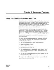
Activating the Sonic Keyfile<br />
1 Launch the Sonic Keyfile Activator application (located in the same folder<br />
as your Sonic application). You will see this dialog:<br />
Figure 1<br />
Sonic Keyfile Activator Dialog<br />
2 Type the Activator Code into the Sonic Keyfile Activator application.<br />
3 Click the OK button. Your keyfiles will automatically be installed in a Sonic<br />
Preferences folder inside your Macintosh System Folder.<br />
4 You may now launch SonicStudio HD.<br />
Please feel free to contact Sonic Studios’ Customer Support at 763-577-1535<br />
with any questions regarding this procedure. Be sure to have your<br />
SonicCare number on hand when you call.
VIII<br />
keyfile.<br />
Warning! Before you activate your key code, remove from the Sonic<br />
Preferences folder (located in the System folder) any existing SonicKey files<br />
that you wish to keep. Existing keyfiles will be overwritten by your new
S O N I C<br />
Sonic Port<br />
Dual AES<br />
Clock Source<br />
InOut<br />
192176.49688.24844.1WSDS1-23-4<br />
JA Lock<br />
<br />
In Out In Out In Out In Out In Out In Out In Out In Out<br />
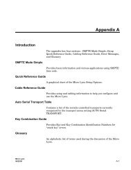
1 HD-1000 Workstation<br />
This chapter describes how to install the hardware for the HDSP<br />
Workstation (HD-1000).<br />
Multi-Channel Digital I/O Conversion System<br />
SOLUTIONS A B C D 1 2 3 4 5 6 7 8<br />
Figure 1-1<br />
The Sonic HDSP Workstation (HD-1000)
1-2 HD-1000 WORKSTATION<br />
What’s <strong>Inc</strong>luded with the HD-1000 Workstations<br />
The HD-1000 and HD-2000 Workstations include the following hardware:<br />
HDSP <strong>Audio</strong> Processor<br />
Sonic HD3 I/O Box<br />
HDSP <strong>Audio</strong> I/O<br />
Cable<br />
HDSP Serial<br />
Adapter Cable<br />
Sonic I/O<br />
Terminator<br />
BNC Terminator<br />
Serial Machine Control &<br />
Timecode Cable<br />
BNC Tee
HD-1000 INSTALLATION Q UICKSTART 1-3<br />
HD-1000 Installation Quickstart<br />
For detailed installation instructions, see "Installing the Hardware" on<br />
page 1-5.<br />
2<br />
Connect external<br />
SCSI devices<br />
1<br />
Install the HDSP card in<br />
the Macintosh<br />
Connect the HDSP<br />
Connect timecode and<br />
3 to the HD3 I/O Box<br />
machine control<br />
4
1-4 HD-1000 WORKSTATION<br />
System Requirements<br />
In addition to the hardware supplied by Sonic, you’ll need the following<br />
components:<br />
Macintosh Computer System<br />
• Power Macintosh G3 or G4 computer<br />
• 128 MB memory minimum (256 MB recommended)<br />
• Mac OS 9.04 or later<br />
• 4 GB internal hard drive (system and applications)<br />
• CD-ROM drive<br />
• 20-inch color monitor<br />
• 24-bit, 1024x768 color graphics card (if not supplied with CPU)<br />
• 18 GB external hard drive (media drive)<br />
• SCSI adapter card<br />
Note: For high clock rate, multi-channel audio, SonicStudio HD requires<br />
an ultra-wide SCSI drive and SCSI accelerator card. For the latest<br />
information regarding approved devices, visit www.sonic.com.<br />
Peripheral Equipment<br />
• A/D and D/A converters: two to eight channels of 44.1 to 96 kHz, or<br />
two channels of 176.4 to 192 kHz (such as the Sonic 888 from Lucid<br />
Technology)<br />
• <strong>Audio</strong> source and monitoring equipment<br />
• Disk image output medium (such as CD-R, Exabyte, Image File or Sony<br />
1630)
I NSTALLING T HE H ARDWARE 1-5<br />
Installing the Hardware<br />
This section presents grounding precautions and detailed instructions for<br />
installing the HD-1000 Workstation hardware.<br />
Grounding Precautions<br />
To assure safety and protect your system components from damage, please<br />
follow these grounding procedures:<br />
• Before making any connections, shut down your Macintosh and any<br />
peripheral equipment that is already connected to it. Never connect or<br />
disconnect components when the power is on unless you are certain<br />
that they are hot-swappable.<br />
• Use only three-pin, grounded AC mains outlets and, if in doubt, test<br />
them before using to ascertain that they are properly wired.<br />
• Never use ground-lifting adapters to defeat the earth ground<br />
connection; this can result in a hazardous condition.<br />
• Use surge-protected outlets to prevent damage from power surges.<br />
• Where possible, connect all components to the same AC circuit; this<br />
will minimize the possibility of ground voltage differentials.<br />
• Handle circuit cards by the edges only, and use the included anti-static<br />
wrist band to avoid damaging sensitive components.
1-6 HD-1000 WORKSTATION<br />
Installing the HDSP Card<br />
To install the HDSP card, you will need:<br />
• A #2 Phillips screwdriver<br />
• The Power Macintosh CPU<br />
• The HDSP PCI card<br />
Figure 1-2<br />
Installing PCI Expansion Cards<br />
To install the HDSP card:<br />
1 Make certain that the Macintosh power is off. Disconnect the power cord.<br />
2 Put on the static protection wrist band and attach the wire to a grounded<br />
terminal.
I NSTALLING T HE H ARDWARE 1-7<br />
3 Open the Macintosh CPU (refer to the instructions that came with your<br />
computer) and locate the PCI expansion slots.<br />
4 Remove the screw that holds the access cover for the third slot from the<br />
hinge in place. Remove the access cover and set it aside.<br />
5 Unpack the HDSP card from its static-proof bag. Handle the card by its<br />
edges: don’t touch the gold connector fingers or on-board components.<br />
Note: If you’ve not already done so, write down the serial numbers for<br />
the HDSP Processor in the space provided on page vi of this manual. You’ll<br />
need this number if you require technical support.<br />
6 Align the card’s connector fingers with the PCI slot and press down until<br />
the card is seated. Reinstall the screw to hold the card in place.<br />
7 Follow steps 4–6 again to install a SCSI accelerator card if SCSI was not<br />
included with your CPU (refer to the documentation for the card to<br />
determine which slot to use).<br />
8 Close the computer. You can now take off the wristband.<br />
Note: Reconnect the Macintosh power cord before continuing the<br />
installation. This will ensure that the computer is safely grounded, and thus<br />
prevent damage from differing ground potentials or stray electrostatic<br />
charges.
1-8 HD-1000 WORKSTATION<br />
SCSI Bus Connections<br />
SonicStudio uses the SCSI (Small Computer System Interface) bus to<br />
communicate with peripheral devices such as media drives, CD-R or DVD-R<br />
units, and digital tape drives. SCSI devices are connected in a daisy-chain<br />
fashion, with the bus connections looping through each successive device.<br />
SCSI peripherals typically have two SCSI connectors, and either connector<br />
can serve as input or output.<br />
Three simple rules govern SCSI bus connections:<br />
• The total physical bus length must not exceed six meters (or less for<br />
Fast, Wide and Ultra SCSI implementations; check the documentation<br />
for your SCSI interface for further information).<br />
• The devices at each end of the bus must be terminated to prevent signal<br />
reflections that can corrupt data.<br />
• Each device in the chain (including the computer’s SCSI port) must be<br />
assigned a unique address.<br />
Additional constraints apply when mixing narrow (8-bit) and wide (16-bit)<br />
devices on the bus. Before making SCSI bus connections, review the<br />
documentation for each peripheral device, the Macintosh and, if<br />
applicable, the PCI SCSI card to familiarize yourself with how they should<br />
be connected.<br />
Tip: For the latest information regarding SCSI connections, check the<br />
Sonic website at www.sonic.com. Additional information about SCSI<br />
connections may be found at the web site of the SCSI Trade Association,<br />
www.scsita.org.
I NSTALLING T HE H ARDWARE 1-9<br />
To connect SCSI peripherals, you will need:<br />
• The peripheral devices<br />
• SCSI cables (normally supplied with the device)<br />
• A SCSI terminator (also often supplied with the device)<br />
• The Power Macintosh CPU<br />
Figure 1-3<br />
Connecting External SCSI Devices<br />
To connect external SCSI devices:<br />
1 Check to see that the Macintosh is plugged in and turned off.<br />
2 Connect the power cords of each peripheral. This will assure that they are<br />
grounded. Do not turn any of the peripherals on.<br />
3 Assign each device a unique address, making certain that none conflicts<br />
with the computer’s SCSI port.
1-10 HD-1000 WORKSTATION<br />
4 Using the supplied cable, connect the Macintosh SCSI port to a peripheral<br />
device. If you are connecting only a single peripheral, attach the SCSI<br />
terminator to the device’s other SCSI port.<br />
5 If you are connecting several peripherals, use the supplied SCSI cables to<br />
loop from one to another. Attach the terminator to the last device in the<br />
chain.
I NSTALLING T HE H ARDWARE 1-11<br />
Connecting the Sonic HD3 I/O Box<br />
The HD3 connects to the HD-1000 Workstation using the Sonic I/O bus.<br />
Similar to SCSI, the Sonic I/O bus requires that devices on the bus have<br />
unique addresses, and the bus must be terminated.<br />
To connect the HD3, you will need:<br />
• The HD3<br />
• The Power Macintosh CPU<br />
• The HDSP <strong>Audio</strong> I/O Cable<br />
• The Sonic I/O Terminator<br />
Figure 1-4<br />
Connecting the Sonic HD3
1-12 HD-1000 WORKSTATION<br />
To connect the HD3:<br />
1 Connect the HD3 power cable to a grounded outlet. Do not turn it on.<br />
2 Attach the smaller connector of the HDSP <strong>Audio</strong> I/O Cable to the<br />
corresponding connector on the HDSP card.<br />
3 Attach the other end of the <strong>Audio</strong> I/O cable to either Sonic I/O port on the<br />
rear panel of the HD3.<br />
4 Attach the terminator to the unused Sonic I/O port on the rear panel of the<br />
HD3.<br />
Note: For connections between the HD3 and external devices, see<br />
"Connections" on page 7.
I NSTALLING T HE H ARDWARE 1-13<br />
Connecting Timecode & Machine Control<br />
Both the HD-1000 and the HD-2000 Workstations read and generate<br />
timecode in the SMPTE and EBU formats. Each also has the capability to<br />
control external audio and video transports. Connections to enable these<br />
features are made using the Machine Control & Timecode Cable.<br />
To connect machine control and timecode, you will need:<br />
• The Macintosh CPU<br />
• The HDSP Serial Adapter Cable<br />
• The Machine Control & Timecode Cable<br />
• Compatible audio and/or video transports<br />
Figure 1-5<br />
Connecting Timecode and Machine Control<br />
To connect timecode and machine control:<br />
1 Attach the smaller connector of the Serial Adapter Cable to the<br />
corresponding connector on the HDSP card.
1-14 HD-1000 WORKSTATION<br />
2 Connect the other end of the Serial Adapter Cable to the corresponding<br />
connector on the Machine Control & Timecode Cable.<br />
3 Connect the XLR-type timecode input and output connectors to your<br />
external device.<br />
4 Connect the nine-pin D-sub mini connectors to the machine control inputs<br />
of suitable and compatible transports.<br />
Note: In Compact Disc mastering applications, the timecode cables also<br />
read and generate PQ subcode bursts.
2 Software Installation/Drive Setup
2-2 S OFTWARE I NSTALLATION/DRIVE S ETUP<br />
Installing Your Software<br />
All SonicStudio HD Workstations include SonicStudio HD software for<br />
editing, assembling and premastering High-Density <strong>Audio</strong>.<br />
To install the software:<br />
1 Load the Sonic CD-ROM in the Macintosh CD-ROM drive.<br />
2 Double-click the Installer icon.<br />
3 Select a drive (normally, the startup drive) and click OK.<br />
4 Follow the directions given by the installer.<br />
5 Restart the computer.<br />
Note: Before using your software, you must activate your Sonic Keyfile.<br />
See Activating the Sonic Keyfile on page vii.
F ORMATTING A S OUND S TORAGE D RIVE 2-3<br />
Formatting a Sound Storage Drive<br />
SonicStudio HD supports a wide variety of SCSI peripherals. Previouslyqualified<br />
hard disks used with SonicStudio USP/SSP systems, that maintain a<br />
data-rate of 3.75 MB or higher, should work with SonicStudio HD. Drives<br />
with lower data-rates may also be operable with SonicStudio HD, however<br />
the data bandwidth may significantly reduce the number of disc channels<br />
available.<br />
Sonic recommends that the HDSP Workstation be configured with Seagate<br />
Cheetah drives (ST118202LW).<br />
See your Apple documentation for details on formatiing and maintaining<br />
HFS and HFS+ formatted volumes.
2-4 S OFTWARE I NSTALLATION/DRIVE S ETUP<br />
Formatting a Sonic Media Drive<br />
SonicStudio HD supports Lightspeed for recording, but disk performance<br />
varies between Lightspeed and HFS. For maximum throughput to<br />
accommodate High Density <strong>Audio</strong>, record to an HFS-formatted hard<br />
drive. We also recommend that you back up to an HFS volume any Project<br />
and EDL files that are stored on a Lightspeed volume.<br />
Note: Lightspeed is not recommended for use with SonicStudio HD<br />
except for transferring files from a MOFS volume to HFS or HFS+.<br />
Note: Sherlock does not support Find File operations on Lightspeed<br />
volumes.<br />
To initialize a Sonic Media Drive:<br />
1 Format the drive using Apple Computer’s Hard Disk Setup.<br />
2 Double-click the LightSpeed Toolkit icon to launch it.<br />
3 When the application has launched, you should see this window:
F ORMATTING A S ONIC M EDIA D RIVE 2-5<br />
Highlight the drive that you wish to format, then click Initialize. You<br />
should see this window:<br />
4 Enter a name for the new media volume and click Initialize.<br />
Caution!<br />
This will erase all data on the disk.<br />
When formatting is completed, the Sonic Lightspeed volume icon will<br />
appear on the desktop:
2-6 S OFTWARE I NSTALLATION/DRIVE S ETUP<br />
Repairing a Lightspeed Media Drive<br />
LightSpeed performs consistency checks whenever a drive is to be<br />
mounted on the desktop. If the consistency check fails, a message displays<br />
in the Finder:<br />
Whenever you see this alert, you should immediately repair the Media<br />
Drive using LightSpeed Toolkit so as to maintain the integrity of your data.<br />
To repair a media drive:<br />
1 Click OK to dismiss the alert box.<br />
2 Launch Lightspeed Toolkit. You will see this window:<br />
3 Highlight the drive that generated the alert and click Repair.
R EPAIRING A L IGHTSPEED M EDIA D RIVE 2-7<br />
Lightspeed Toolkit will begin scanning and repairing the drive. While the<br />
repair is in process, you will see a status bar indicating progress:<br />
When the repair is completed, the Lightspeed volume icon will reappear<br />
on the desktop.
2-8 S OFTWARE I NSTALLATION/DRIVE S ETUP
3 The Sonic HD3 I/O Box<br />
This chapter describes the physical and electrical characteristics of the<br />
Sonic High-Density <strong>Audio</strong> Digital I/O Conversion System (HD3).
3-2 T HE S ONIC HD3 I/O BOX<br />
Overview of the HD3<br />
The HD3 is an input/output box for connecting SonicStudio to external<br />
digital audio devices.<br />
Housed in a single-space rack-mountable chassis, the HD3 accommodates<br />
up to eight channels of 24-bit digital audio at standard clock speeds ranging<br />
from 44.1 kHz to 96 kHz, or two channels at 192 kHz. It features sub-nanosecond<br />
sample reclocking and jitter annulment for ultra-stable signal transmission,<br />
and supports digital audio signal connections in all current High-<br />
Density <strong>Audio</strong> formats — AES/EBU, double-speed AES, dual-wire AES and<br />
quad-speed AES.<br />
The number of available channels in SonicStudio HD is affected by the<br />
sample bit rate at which you choose to work. If you are working at 44.1 or<br />
48 kHz, two HD3s can be cascaded on a single HDSP card to provide up to<br />
sixteen channels of 24-bit digital audio. For High-Density <strong>Audio</strong>, SonicStudio<br />
HD accommodates up to three HDSP Processors — each connected to a<br />
single HD3 — for twenty-four channels of 24-bit, 96 kHz audio.<br />
S O N I C<br />
Multi-Channel Digital I/O Conversion System<br />
Sonic Port<br />
Dual AES<br />
Clock Source<br />
In Out In Out In Out In Out In Out In Out In Out In Out<br />
SOLUTIONS A B C D InOut<br />
192176.49688.24844.1WSDS1-23-4<br />
JA Lock 1 2 3 4 5 6 7 8<br />
<br />
Figure 3-1<br />
The Sonic High-Density <strong>Audio</strong> Digital I/O Conversion<br />
System
S AFETY I NFORMATION 3-3<br />
Safety Information<br />
This table lists important safety information. To assure safe operation,<br />
please read and follow these cautions when installing and operating the<br />
Sonic HD3.<br />
Name<br />
Description<br />
Power Source<br />
Grounding<br />
Danger from loss of ground<br />
Proper Power Cord<br />
The Sonic HD3 is intended to operate from a<br />
power source that does not apply more than<br />
250V rms between the power supply conductors<br />
or between either power supply conductor and<br />
ground. A protective ground connection, by way<br />
of the grounding conductor in the power cord, is<br />
essential for safe operation.<br />
The chassis of the Sonic HD3 is grounded<br />
through the grounding conductor of the power<br />
cord. To avoid electric shock, plug the power<br />
cord into a properly wired receptacle before<br />
making any connections to the product. A<br />
protective ground connection, by way of the<br />
grounding conductor in the power cord, is<br />
essential for safe operation.<br />
If the protective ground connection is lost, all<br />
accessible conductive parts, including knobs and<br />
controls that may appear to be insulated, can<br />
cause an electric shock.<br />
Use only the power cord and connector<br />
specified for the product and your operating<br />
locale.<br />
Use only a cord that is in good condition.
3-4 T HE S ONIC HD3 I/O BOX<br />
Name<br />
Description<br />
Operating Location<br />
Stay out of the box<br />
User-serviceable parts<br />
Do not operate the equipment under any of the<br />
following conditions:<br />
explosive atmospheres, in wet locations, in<br />
inclement weather, using improper or unknown<br />
AC mains voltages, using improper fuses.<br />
To avoid personal injury or possibly fatal shocks,<br />
always keep all covers and panels on the<br />
equipment. Always operate the product with the<br />
covers and panels properly installed.<br />
There are no user-serviceable parts inside the<br />
Sonic HD3. In case of failure, contact Sonic<br />
customer support.
F RONT-PANEL I NDICATORS 3-5<br />
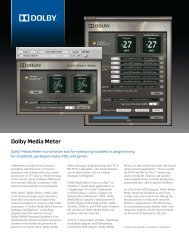
Front-Panel Indicators<br />
The HD3 front panel incorporates a number of LED indicators that display<br />
input and output signal status.<br />
S O N I C<br />
Multi-Channel Digital I/O Conversion System<br />
Sonic Port<br />
Dual AES<br />
Clock Source<br />
In Out In Out In Out In Out In Out In Out In Out In Out<br />
SOLUTIONS A B C D InOut<br />
192176.49688.24844.1WSDS1-23-4<br />
JA Lock 1 2 3 4 5 6 7 8<br />
<br />
Sonic I/O Port<br />
Status Indicators<br />
Dual AES Input/Output<br />
Clock Speed Indicators<br />
Figure 3-2<br />
Clock Source<br />
Indicators<br />
Jitter Attenuation<br />
Lock Indicator<br />
The HD3 Front Panel<br />
Word Sync<br />
Lock Indicator<br />
<strong>Audio</strong> Input & Output<br />
Status Indicators<br />
• Sonic I/O Port — This set of four indicators displays which SonicStudio<br />
I/O port is selected. The LED corresponding to the active port glows<br />
green; if all four LEDs are off, the HD3 is disabled. Port A is the default,<br />
B is optional and the other two are not currently supported.<br />
• Dual AES Input & Output — These two LEDs indicate the input and<br />
output AES clock speed. The indicator glows green if you are using 1x<br />
AES, and is off if you are using double-speed.<br />
• Clock Source — The indicator which is lit denotes the source from<br />
which digital clock is derived. If the indicated clock source is not the<br />
master, then the DS (digital sync) indicator will light. The last two LEDs<br />
at the right glow green for channels 1-2/3-4 and amber for 5-6/7-8.<br />
• JA — When the jitter attenuation circuit is locked to the clock source,<br />
this indicator glows green. If it is red, the circuit is not locked and audio<br />
outputs will mute.<br />
• Word Sync Lock — This indicator glows green if the HD3 is locked to<br />
an input word sync signal, and amber if it is not locked. If there is no<br />
signal at the word sync input, the indicator is off.<br />
• <strong>Audio</strong> In & Out Status — For each individual audio channel, a pair of<br />
LEDs indicates signal status. When the indicator is green, signal is<br />
present. Intensity corresponds to signal level; red indicates clipping.
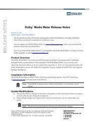
3-6 T HE S ONIC HD3 I/O BOX<br />
Rear-Panel Switches & Connectors<br />
The HD3 rear panel incorporates provisions for connecting it to<br />
SonicStudio and additional converters, assigning it a unique address on the<br />
Sonic bus, and making both digital audio and word sync connections.<br />
WS<br />
16 8 4 2 1<br />
Sonic I/O<br />
In<br />
1-2 Out In 3-4 Out In 5-6 Out In 7-8 Out In<br />
Out<br />
Addr<br />
Digital <strong>Audio</strong><br />
Inputs & Outputs<br />
Word Sync<br />
Input & Output<br />
Address<br />
DIP Switch<br />
Sonic I/O<br />
Connectors<br />
Figure 3-3<br />
The HD3 Rear Panel<br />
• Digital <strong>Audio</strong> In & Out — These balanced, XLR-style connectors<br />
conform to the AES/EBU standard (pin 3 hot).<br />
• Word Sync In — This BNC-type connector accepts word sync from an<br />
external generator.<br />
• Word Sync Out — You can use this BNC-type output to deliver word<br />
sync from the HD3’s system clock to external devices. Do not daisychain<br />
word sync from this connector to other Sonic I/O boxes.<br />
• Address DIP Switch — Each converter on the Sonic bus must have a<br />
unique address between 1 and 31, and the address of the HD3 is set<br />
using these switches. For example, to set the address to 3, the switches<br />
should be as shown here:<br />
16 8 4 2 1<br />
Do not use ID 0 (all switches down); it is reserved for the HDSP card.<br />
• Sonic I/O — These 68-pin connectors are used to connect the HD3 to<br />
SonicStudio or to other converter boxes. The last box in the chain must<br />
be properly terminated.
C ONNECTIONS 3-7<br />
Connections<br />
This section describes connections between the HD3 and external devices,<br />
including digital audio inputs/outputs and word sync sources.<br />
Digital <strong>Audio</strong> Inputs & Outputs<br />
The table below summarizes cable and speed configurations for the audio<br />
input and output formats that the HD3 accommodates:<br />
Clock<br />
Frequency<br />
Channels<br />
per Cable<br />
Number<br />
of Cables<br />
Speed<br />
Name<br />
44.1 kHz 2 1 1x AES/EBU<br />
96 kHz 2 1 2x Double-Speed AES<br />
96 kHz 1 2 1x Dual-Wire AES<br />
192 kHz 1 2 2x Double-Speed/Dual-Wire<br />
192 kHz 0.5 4 1x Quad-Wire AES<br />
The figures on the next page illustrate the assignments of input and output<br />
connectors for AES/EBU or double-speed AES connections, and dual-wire<br />
AES connections, respectively.<br />
For detailed information on wiring cables and connectors, see Appendix A,<br />
"Connector Wiring."
3-8 T HE S ONIC HD3 I/O BOX<br />
AES/EBU OR DOUBLE-SPEED AES CONNECTIONS<br />
The HD3 supports up to eight input and output channels in AES/EBU or<br />
double-speed AES mode.<br />
WS<br />
16 8 4 2 1<br />
Sonic I/O<br />
In<br />
1-2 Out In 3-4 Out In 5-6 Out In 7-8 Out In<br />
Out<br />
Addr<br />
Channels<br />
1 & 2<br />
Channels<br />
3 & 4<br />
Channels<br />
5 & 6<br />
Channels<br />
7 & 8<br />
Figure 3-4<br />
AES/EBU or Double-Speed AES Channel Assignments<br />
DUAL-WIRE AES CONNECTIONS<br />
The HD3 supports up to four input and output channels in dual-wire AES<br />
mode.<br />
WS<br />
16 8 4 2 1<br />
Sonic I/O<br />
In<br />
1-2 Out In 3-4 Out In 5-6 Out In 7-8 Out In<br />
Out<br />
Addr<br />
Channel 1 Channel 2 Channel 3 Channel 4<br />
Figure 3-5<br />
Dual-Wire AES Channel Assignments
C ONNECTIONS 3-9<br />
Word Sync<br />
You can connect an external word sync generator to the HD3 WS In using<br />
a standard BNC-BNC cable. The HD3 can also deliver word sync from its<br />
internal system clock to other devices through its WS Out connector.<br />
To loop input word sync between multiple I/O boxes, use the BNC tee<br />
included with the HD3. The last unit in the word sync chain must be<br />
terminated. To do so, use the BNC tee and attach the terminator (included<br />
with the HD3) as shown in Figure 3-6.<br />
BNC Terminator<br />
16 8 4 2 1<br />
Sonic I/O<br />
In<br />
1-2 Out In 3-4 Out In 5-6 Out In 7-8 Out In<br />
Out<br />
Addr<br />
BNC Tee<br />
Word Sync Cable<br />
Figure 3-6<br />
Installation of BNC Terminator on Word Sync Input<br />
Multi-Channel Expansion<br />
The method for multi-channel expansion of your SonicStudio HD system<br />
depends upon the clock speed for the audio streams that you wish to<br />
accommodate.<br />
If you are working only in 44.1 or 48 kHz, you can cascade a second<br />
HD I/O from the first one using a Sonic 68-pin connector cable (included)<br />
between the devices’ Sonic I/O ports. Attach a 68-pin terminator (included)<br />
to the second device’s open Sonic I/O port.
3-10 THE S ONIC HD3 I/O BOX<br />
If you are working in High-Density <strong>Audio</strong> (clock speeds of 88.2 kHz or<br />
higher), you are limited to one HD3 per HDSP card. This means that HD-<br />
1000 or HD-2000 Workstation owners who desire additional High-Density<br />
<strong>Audio</strong> channels must purchase and install an Expansion Chassis. To add<br />
channels to your system, install one or more additional HDSP cards in the<br />
Expansion Chassis and connect each HD3 separately to them using the<br />
cable provided.
C ONFIGURING T HE S YSTEM 3-11<br />
Configuring the System<br />
Once the HD3 is connected, SonicStudio must be configured to work with<br />
it. The <strong>Audio</strong> I/O Preferences dialog sets the configuration of SonicStudio's<br />
digital inputs and outputs.<br />
To set digital inputs and outputs:<br />
1 Select an audio source to verify proper operation. Make sure that the<br />
device has power and is supplying a signal to the HD3.<br />
2 Select a pair of outputs from the HD3 and connect them to a monitoring<br />
system.<br />
3 Launch SonicStudio HD and choose File > Preferences > <strong>Audio</strong> I/O...<br />
The <strong>Audio</strong> I/O Preferences dialog will appear:<br />
Global<br />
Controls<br />
Master Clock<br />
Information &<br />
Controls<br />
HDSP Board<br />
Information &<br />
Controls<br />
Status Area
3-12 THE S ONIC HD3 I/O BOX<br />
This dialog controls the physical connections of the system. If necessary,<br />
use the Board pop-up menu to select the correct HDSP card. The HD3 I/O<br />
Box appears as an icon labeled HD3.<br />
Global Controls<br />
At the top of the window is an area with two global controls.<br />
Rescan I/O — Click on this button to scan the Sonic I/O bus for<br />
converters.<br />
Auto Input Muting — When this box is checked, SonicStudio mutes<br />
digital inputs that show bad parity or non-synchronous clock.<br />
Setting the Master Clock Source<br />
Digital audio systems require a master clock that is common to all devices<br />
in the system. SonicStudio derives its clock from any of several sources and<br />
will not function properly without a valid clock.<br />
To configure the Master Clock:<br />
1 The Master Clock icon appears in the converter window "docked" to the<br />
device that is the designated clock source. If it is not docked to the HD3,<br />
click-hold on the clock icon and drag it onto the HD3.<br />
2 Click-hold on the Clock Source pop-up and drag to select a master clock<br />
source (Word Sync, Internal or Digital Input).<br />
3 Select Double Speed In if your clock source is 98 kHz word sync. Select<br />
Double Speed Out if you want SonicStudio to generate 96 kHz word<br />
sync.
C ONFIGURING T HE S YSTEM 3-13<br />
If you find that SonicStudio is unable to sync with the selected clock, the<br />
source may be jittery or unstable. Selecting Wide Input Jitter can<br />
sometimes solve this problem.<br />
Similarly, you may need to select Phase Invert in order to sync properly<br />
with some word sync source devices.<br />
If the Master Clock settings you have chosen are valid for the HD3, the<br />
clock icon will appear with a black border and hands. If the settings are not<br />
valid, the icon will appear with a flashing red border and hands; check the<br />
status area at the bottom of the window for an indication of error status.<br />
Configuring the HDSP Board<br />
1 Click-hold on the board Mode pop-up and drag to select the DSP mode for<br />
the HDSP board.<br />
2 Select 2x AES Speed Input if you are feeding your SonicStudio<br />
Workstation from a 96 kHz double-speed AES source.<br />
3 Select 2x AES Speed Output if you want your SonicStudio Workstation to<br />
send a 96 kHz double-speed AES signal.<br />
You can use the Identify buttons to distinguish which converter box(es)<br />
the HDSP board is addressing:<br />
• When you click on Rx, the indicators on all boxes providing input to<br />
the selected HDSP board will flash for two seconds.<br />
• When you click on Tx, the indicators on all boxes providing output<br />
from the selected HDSP board will flash for two seconds.<br />
To flash the converter indicators continuously, place the cursor over the<br />
Input Status Strip on the right hand side of the converter display box after<br />
clicking either Rx or Tx.
3-14 THE S ONIC HD3 I/O BOX<br />
The HD3 Converter Display<br />
Each converter connected to the selected HDSP board is represented by a<br />
horizontal bar in the converter window. The available configuration options<br />
will vary depending upon the specific converter. These instructions apply<br />
to the HD3 I/O Box.<br />
Figure 3-7<br />
The HD3 <strong>Audio</strong> I/O Panel<br />
L1/2 – L7/8 — These pop-ups control the status of the HD3 I/O Box digital<br />
audio inputs. To enable an input pair, click-hold on its pop-up and select<br />
AES. To disable an input pair, select None.<br />
Viewing & Editing the Channel Status<br />
The Channel Status dialog allows you to:<br />
• Read the channel status settings of incoming digital audio signals<br />
• View and edit the hexadecimal status bits for output channels<br />
• Read and write template files that store status bit settings<br />
To view the audio Channel Status dialog:<br />
In the HD3 converter bar, -click on the signal status LED for the channel<br />
pair that you wish to edit. You can also -click on the HD3 icon to open<br />
the Channel Status dialog for the first channel pair.
C ONFIGURING T HE S YSTEM 3-15<br />
The following dialog appears:<br />
Input<br />
Section<br />
Output Channel<br />
Status Fields<br />
INPUT SECTION<br />
The input section displays the status of the input signal for the currently<br />
selected channel pair. Channel pairs are selected using the pop-up box in<br />
the upper left corner of the dialog box.<br />
Input Status — This indicator has five color states. Green indicates that<br />
the input is enabled and a valid, synchronous signal is present. Red<br />
indicates that the input signal is invalid or not synchronized to the Master<br />
Clock. Red crossed out indicates that the input signal is not locked and the<br />
input is muted. Yellow indicates that the input is enabled but no signal is<br />
present. Gray means that the input is disabled.<br />
CRC — CRC stands for Cyclic Redundancy Check, a method for detecting<br />
errors in a digital audio signal. CRC errors may arise from data corruption<br />
or lack of synchronization between the source and receiver. The CRC A<br />
indicator is for channel 1 of the AES input pair, and CRC B is for channel 2.<br />
Green indicates a valid input signal, red indicates CRC errors and gray<br />
indicates a lack of CRC signal.
3-16 THE S ONIC HD3 I/O BOX<br />
OUTPUT STATUS FIELDS<br />
Signal Type — Professional is AES/EBU (XLR connector), Consumer is<br />
S/PDIF (RCA-type connector, not available with the HD3) and Hex<br />
indicates that only the hexadecimal status bits shown in the display will<br />
apply to the output.<br />
Generate CRC — (AES/EBU only) When this item is checked, Cyclic<br />
Redundancy Check bits will be generated on the currently selected channel<br />
pair.<br />
Copy Permit — (S/PDIF only) When this item is checked, the copy<br />
prohibit flag will be set on the currently selected outputs, preventing<br />
consumer devices that sense this flag from recording the signal.<br />
Sample Rate — Select Auto to slave the outputs to your Master Clock<br />
sampling rate. You may also choose 32, 44.1 or 48 kHz.<br />
Category — (S/PDIF only) Select General, PCM, CD or DAT.<br />
Emphasis — This item controls setting of the emphasis flag. Select On<br />
when playing an EDL to which you have applied the emphasis filter, or Off<br />
if you do not use emphasis. Follow Marks is used for background dumps<br />
of EDLs containing start-of-track marks with Emphasis checked.<br />
Hexadecimal Status Bits — Output status items are encoded in<br />
designated bits of the channel status block. Refer to the SonicStudio User<br />
Guide for a list of status bit values and their meanings.<br />
The Reset button reverts from any changes made to the status bits. The<br />
Translate button applies the readout values to the channel status fields.<br />
You can also store and retrieve status field settings using the Read<br />
Template and Write Template buttons.<br />
To display the channels status of the input signal, click the Read Input<br />
button. To display the channels status of the output signal, click the Read<br />
Output button. The Set Output button applies status bit changes to the
C ONFIGURING T HE S YSTEM 3-17<br />
current output channel, and the Cancel button closes the Channel Status<br />
Dialog without applying any changes. To apply changes and close the<br />
dialog, click OK.
3-18 THE S ONIC HD3 I/O BOX
A<br />
Connector Wiring<br />
This section provides detailed information on wiring input and output<br />
audio cables and connectors for the HD3 I/O Box and A-V I/O.
A-2 C ONNECTOR W IRING<br />
HD3 Connections<br />
When wiring digital audio inputs and outputs, choose a high-quality,<br />
shielded, twisted-pair cable with 110 ohm characteristic impedance and a<br />
low capacitance-per-foot rating (12–13 pf/ft).<br />
AES/EBU Inputs<br />
The HD3 AES/EBU inputs conform to the AES3 1992 specification. They are<br />
transformer-coupled, and present a 110 ohm impedance. Cables for<br />
connecting AES/EBU sources to the HD3 should be wired as shown in<br />
Figure A-1.<br />
Transmitter<br />
AES/EBU Output<br />
XLR-3M<br />
XLR-3F<br />
HD3 I/O Box<br />
AES/EBU Input<br />
Out +<br />
3<br />
+<br />
Twisted pair<br />
+<br />
3<br />
.1µ<br />
In +<br />
110<br />
Out -<br />
2<br />
-<br />
-<br />
2<br />
In -<br />
Out gnd<br />
1<br />
Case<br />
NC<br />
Shield<br />
1<br />
Case<br />
Figure A-1<br />
Connecting AES/EBU Sources to the HD3 I/O Box<br />
Note that the cable shield connects only at the HD3 input connector. This<br />
telescoping arrangement preserves the advantages of transformer isolation<br />
and eliminates the possibility of ground loops.<br />
AES/EBU Outputs<br />
The HD3 AES/EBU outputs conform to AES3 1985 and 1992, both of which<br />
specify a 110-ohm source impedance with transformer coupling. Output<br />
connections differ slightly, however, depending upon whether the receiver<br />
input is configured for AES3 1985 or AES3 1992: the earlier specification<br />
calls for a 250-ohm input impedance, while the later one specifies a 110-<br />
ohm input impedance.
HD3 CONNECTIONS A-3<br />
When connecting to AES3 1992 inputs, wire the cables and connectors as<br />
shown in Figure A-2.<br />
Out +<br />
Sonic<br />
AES/EBU Output<br />
.1µ 110<br />
XLR-3M<br />
3<br />
+<br />
Twisted pair<br />
+<br />
XLR-3F<br />
3<br />
.1µ<br />
Receiver<br />
AES/EBU Input<br />
(AES3 1992)<br />
In +<br />
Out -<br />
2<br />
-<br />
-<br />
2<br />
110<br />
In -<br />
1<br />
NC<br />
1<br />
In gnd<br />
Case<br />
Shield<br />
Case<br />
Figure A-2<br />
Connecting to AES3 1992 Inputs<br />
When connecting to AES3 1985 inputs, wire the cables and connectors as<br />
shown in Figure A-3.<br />
Out +<br />
Sonic<br />
AES/EBU Output<br />
.1µ 110<br />
XLR-3M<br />
3<br />
+<br />
Twisted pair<br />
+<br />
XLR-3F<br />
3<br />
.1µ<br />
Receiver<br />
AES/EBU Input<br />
(AES3 1985)<br />
In +<br />
196 250<br />
Out -<br />
2<br />
-<br />
-<br />
2<br />
In -<br />
1<br />
NC<br />
1<br />
In gnd<br />
Case<br />
Shield<br />
Case<br />
Figure A-3<br />
Connecting to AES3 1985 Inputs<br />
Note the addition of a 196 ohm resistor across pins 2 and 3 of the receiver<br />
input. This resistor matches the input’s impedance to that of the HD3<br />
output, reducing the likelihood of destructive reflections on the line. It can<br />
be installed directly in the XLR connector.
A-4 C ONNECTOR W IRING
FCC Information<br />
Warning! Changes or modifications to this unit not expressly approved by the<br />
party responsible for compliance could void the user’s authority to operate the<br />
equipment.<br />
This equipment may generate, use, and can radiate radio frequency energy and, if<br />
not installed and used in accordance with the instructions, may cause harmful<br />
interference to radio communications.<br />
When printed circuit boards are properly installed in a host computer, the<br />
computer chassis should provide protection against harmful interference in a<br />
typical installation. Rack mount or stand alone units utilize their chassis or housing<br />
to provide protection against harmful interference, therefore they should not be<br />
opened or operated without their original enclosures.<br />
However, there is no guarantee that interference will not occur in a particular<br />
installation. If this equipment does cause harmful interference to radio or television<br />
reception, which can be determined by turning the equipment on and off, the user<br />
is encouraged to try to correct the interference by one or more of the following<br />
measures:<br />
• Reorient or relocate the receiving antenna.<br />
• <strong>Inc</strong>rease the separation between the equipment and receiver.<br />
• Connect the equipment to an outlet on a circuit different from that to which<br />
the receiver is connected.<br />
• Consult the dealer or an experienced radio/TV technician for assistance.<br />
Note: Shielded data and audio cables should be used with this equipment to<br />
ensure compliance with the radio frequency emission limits for this device.
FCC Statement<br />
This device complies with part 15 of the FCC Rules. Operation is subject to the<br />
following two conditions: (1) This device may not cause harmful interference, and<br />
(2) this device must accept any interference received, including interference that<br />
may cause undesired operation.<br />
Declaration of Conformity<br />
Application of Council Directive(s):<br />
Standard(s) to which Conformity is Declared:<br />
89/336/EEC<br />
EN55022 Class A<br />
EN50081-1<br />
EN50082-1<br />
EN61000-4-2(1995)<br />
EN61000-4-4(1995)<br />
ENV50140(1994)<br />
ENV50141(1994)<br />
Manufacturer’s Name<br />
European Representative<br />
Sonic Solutions<br />
Sonic Europe<br />
101 Rowland Way 21/22 Warwick Street<br />
Novato, CA 94945 USA<br />
London, UK, W1R 5RB<br />
415-893-8000 Voice 44.171.437.1100 Voice<br />
415-893-8008 Fax 44.171.437.1151 Fax<br />
Type of Equipment:<br />
Product:<br />
SonicStudio HD Workstations<br />
Sonic A-V I/O
Declaration of Conformity<br />
Application of Council Directive(s):<br />
Standard(s) to which Conformity is Declared:<br />
89/336/EEC<br />
FCC Part 15 Subpart B (emissions)<br />
Industry Canada 1CES-003<br />
EN55103-1 (emissions)<br />
EN55103-2 (immunity)<br />
Manufacturer’s Name<br />
Sonic Solutions<br />
101 Rowland Way<br />
Novato, CA 94945 USA<br />
415-893-8000 Voice<br />
415-893-8008 Fax<br />
European Representative<br />
MediArte Musik- und Medienkonzepte GmbH<br />
Theodorstrasse 100<br />
D-40472 Düsseldorf<br />
Germany<br />
Phone +49 211 94271-0<br />
Fax +49 211 94271-22<br />
eMail markus.hintz@mediarte.com<br />
Info http://www.mediarte.com<br />
Type of Equipment:<br />
Product:<br />
SonicStudio HD Workstations<br />
Sonic <strong>Audio</strong> I/O
Declaration of Conformity<br />
Application of Council Directive(s):<br />
89/336/EEC<br />
Standard(s) to which Conformity is Declared: EN50081-1<br />
EN55022 A (1995)<br />
CISPR22 A (1993)<br />
VCCI-1<br />
EN50082-1 (1997)<br />
EN61000 4-2<br />
EN61000 4-3<br />
ENV50204<br />
EN61000 4-4<br />
EN61000 4-5<br />
EN61000 4-6<br />
EN61000 4-8<br />
EN61000 4-11<br />
Manufacturer’s Name<br />
European Representative<br />
Sonic Solutions<br />
Sonic Europe<br />
101 Rowland Way 21/22 Warwick Street<br />
Novato, CA 94945, USA<br />
London, UK, W1R 5RB<br />
415-893-8000 Voice 44.171.437.1100 Voice<br />
415-893-8008 Fax 44.171.437.1151 Fax<br />
Type of Equipment:<br />
Product(s):<br />
SonicStudio HD Workstations<br />
MPEG-2 Encoder<br />
Sonic A-V Processor<br />
Sonic Dolby Digital Encoder<br />
SonicStudio 16:24 <strong>Audio</strong> Processor<br />
PCI Expansion Chassis<br />
SonicStudio 16:24 FX Background<br />
Processor<br />
SonicStudio HDSP Processor<br />
HD I/O Converter Box<br />
SonicStudio HDSP FX Processor
Index<br />
A<br />
address<br />
SCSI 1-9<br />
Sonic I/O 3-6<br />
AES/EBU<br />
input 3-6, 3-8, A-2<br />
output 3-6, 3-8, A-2<br />
B<br />
BNC<br />
tee 3-9<br />
terminator 3-9<br />
C<br />
CD-R 1-8<br />
clock<br />
source indicators 3-5<br />
speed 3-7<br />
connections<br />
audio, HD3 I/O Box 3-7, A-2<br />
double-speed AES 3-8<br />
dual-wire AES 3-8<br />
HD3 I/O Box 1-11<br />
machine control 1-13<br />
SCSI 1-8<br />
word sync 3-8<br />
D<br />
double-speed AES 3-8<br />
dual-wire AES 3-8<br />
DVD-R 1-8<br />
E<br />
Expansion Chassis 3-10<br />
F<br />
formatting a media drive 2-3, 2-4<br />
G<br />
grounding 1-5, 1-7, 3-3, A-2<br />
H<br />
HD3 I/O Box 1-2<br />
connecting 1-11, 3-7, A-2<br />
front panel 3-5<br />
overview 3-2<br />
rear panel 3-6<br />
safety information 3-3<br />
HDSP<br />
audio I/O cable 1-2, 1-11<br />
card 1-2, 1-6<br />
serial adapter cable 1-2, 1-13<br />
High-Density <strong>Audio</strong>
I-2 INDEX<br />
I<br />
formats 3-2, 3-7, 3-8<br />
system requirements 1-4, 1-8,<br />
3-10<br />
indicators<br />
audio status 3-5<br />
clock source 3-5<br />
dual AES 3-5<br />
jitter attenuation 3-5<br />
Sonic I/O port 3-5<br />
word sync lock 3-5<br />
installer 2-2<br />
J<br />
jitter attenuation 3-5<br />
K<br />
Keyfile 2-2<br />
activating 1-vii–<br />
L<br />
Lightspeed Toolkit 2-3, 2-4, 2-6<br />
M<br />
machine control<br />
cable 1-2, 1-13<br />
connecting 1-13<br />
media drive 1-4, 1-9<br />
formatting 2-3, 2-4<br />
repairing 2-6<br />
P<br />
PCI<br />
slots 1-7<br />
peripheral equipment 1-4<br />
connecting 1-8<br />
PQ subcode 1-14<br />
Q<br />
quickstart<br />
HD-1000/2000 1-3<br />
R<br />
repairing a media drive 2-6<br />
S<br />
safety information 1-5, 1-7<br />
SCSI<br />
accelerator card 1-4, 1-7<br />
address 1-9<br />
description 1-8<br />
media drive 1-4<br />
termination 1-10<br />
Sonic I/O<br />
port 3-5, 3-6, 3-9<br />
terminator 1-2, 1-11<br />
Sonic Keyfile 2-2<br />
activating 1-vii–<br />
SonicCare 1-vi<br />
system requirements 1-4<br />
T<br />
technical support 1-vi<br />
terminator<br />
SCSI 1-10<br />
Sonic I/O 1-2, 1-11<br />
word sync 1-2<br />
timecode<br />
cable 1-2, 1-13<br />
connecting 1-13<br />
W<br />
word sync<br />
connecting 3-8<br />
input & output 3-6<br />
lock indicator 3-5<br />
terminator 1-2, 3-9