chapter 9 advanced features.pdf - Audio Intervisual Design, Inc.
chapter 9 advanced features.pdf - Audio Intervisual Design, Inc.
chapter 9 advanced features.pdf - Audio Intervisual Design, Inc.

Create successful ePaper yourself
Turn your PDF publications into a flip-book with our unique Google optimized e-Paper software.
Chapter 9 Advanced FeaturesUsing AVID <strong>Audio</strong>Vision with the Micro Lynx<strong>Audio</strong>Vision Version 2.0 includes support of TimeLine Vista, <strong>Inc</strong>.'sMicro Lynx synchronizer. Using the Micro Lynx with <strong>Audio</strong>Visionwill enable you to control many external decks that cannot bedirectly controlled using Sony 9-pin protocol. The Micro Lynx alsoallows you to output time code from <strong>Audio</strong>Vision and slave<strong>Audio</strong>Vision from an external time code source.This section outlines the basic steps necessary to connect theMicro Lynx to <strong>Audio</strong>Vision and use it to control one or multipledecks. It is assumed that you are familiar with operating theMicro Lynx, or that you have read the Getting Started section ofthe user's manual. If you are not already familiar with the MicroLynx, read the appropriate sections before attempting to use itwith <strong>Audio</strong>Vision.On power up, <strong>Audio</strong>Vision automatically configures the MicroLynx for correct operation. The following setup options areinitialized by <strong>Audio</strong>Vision:• The Mac computer port is set for ES bus operation.• Park Window is set to zero.• Group park ahead is set to zero.• Ref follow master is set to on.• The System reference is set External Video, unless a VSG(video sync generator) board is fitted, then it will be set toInternal fixed.• The ACG card input and output is set to 44.100 KHz and theOversample rate to 256.To complete the configuration, all that has to be selected is thetype of transport to be controlled.Micro Lynx06/22/00 9-1
Advanced FeaturesThe Avid system requires that a transport be selected for an Avidnode to be active. If it is intended to use <strong>Audio</strong>Vision in slavemode, to a time code “feed” with no transport connected, werecommend that an ATR transport be selected.To Control One Transport Device with the Micro Lynx1. With all hardware powered off, connect a machine controlcable and a time code cable between the Micro Lynx and thedeck you want to control. The machine control cable isconnected from the Micro Lynx's Transport 1 connector to thedeck's remote control input, and the time code cable isconnected from the deck to the RDR 1 input on the Micro Lynx.2. Use a standard Macintosh printer cable to connect yourMacintosh's modem port to the Micro Lynx's Macintosh port.Note: Be sure to use a standard Macintosh printer cable toconnect the Mac to the Micro Lynx, not a Mac to 9-pin cable.Connecting the Mac to the Micro Lynx's 9-pin port can resultin inaccuracies in time code when digitizing material into<strong>Audio</strong>Vision.3. Connect a black burst source to the Video Ref port on the MicroLynx, and to the video machine you are controlling.4. Use a BNC cable to connect the ACG-2 card's OS OUT (on theMicro Lynx) to the first Digidesign <strong>Audio</strong> Interface's SlaveClock input.5. Power on the Micro Lynx.6. On the Micro Lynx Keyboard, the group select keys will flash,press machine key A.7. Next, you need to specify the type of machine you are using.Enter setup mode in the Micro Lynx by pressing the [SETUP]key on the keyboard. Press the [TRAN] key to select the typeof machine you are synchronizing. Use the [Next/Last] and[+] and [–] keys to select the correct type from the menu.Note: If your deck does not appear in the menu, refer to theAppendix, Table 2, for alternate choices.8. While in setup mode, the default option settings initialized by<strong>Audio</strong>Vision can be checked by pressing the respective optionkey and the [Last/Next] keys to step to the desired menu. Forexample, press the [TCG] key and use the [Last/Next] keys toselect the System Ref menu. This should normally be set toExt Vid. For a complete list of setup options, please see theAppendix.Micro Lynx9-2 06/22/00
Advanced Features9. Press the [SETUP] key to leave setup mode.10. Set up <strong>Audio</strong>Vision in Master Mode just as you would if youwere using Sony protocol or VLANs. You are now ready tosynchronize the Micro Lynx to <strong>Audio</strong>Vision.Note: The Micro Lynx will remember the settings you haveprogrammed when you power down, there is no need to repeatthe setup steps every time you use the system.To Control Multiple Transport Devices with the Micro LynxFollow the above steps, but repeat steps 6 and 7 for eachadditional deck. In Step 6, select A for Deck 1, B for Deck 2, etc.To Slave <strong>Audio</strong>Vision from an External Deck Connected to the Micro Lynx1. If you are only going to slave <strong>Audio</strong>Vision from an externaldeck, and don't need to operate <strong>Audio</strong>Vision in Master Mode,you only need to connect the time code cable from the machineto the Micro Lynx.2. Follow the above directions, but set <strong>Audio</strong>Vision to Slave Modefrom the Deck Control window. <strong>Audio</strong>Vision is now set toslave to the deck connected to the Micro Lynx.Micro Lynx06/22/00 9-3
Advanced FeaturesUsing Pro Tools with the Micro LynxIntroductionThe Micro Lynx machine control system has special <strong>features</strong> thatmake it suitable for use with Digi<strong>Design</strong> Pro Tools digital audioworkstations.• The MIDI and SMPTE time code generators can besynchronized with the tape machine group; operating asvirtual tape machines, chasing the reference machine timecode numbers.• If the MTC output is connected to Pro Tools, the workstationwill run as if it were a tape machine. This also holds true forMIDI synthesizers and MIDI mapping systems.• The Micro Lynx is specifically designed to generate a digitalclock speed reference for digital work stations. The <strong>Audio</strong>Clock Generator option cards (ACG-1 & 2) generate locked,digital audio clock signals to control the play speed or samplerate of digital equipment.• Pro Tools is very similar in operation to a video tape machine,in that it uses time code for position, but when in play,“releases” to an internal or external reference, which thencontrols its speed and position. The ACG can be used as thePro Tools reference.• If the Micro Lynx is equipped with a VITC Option Card, it willupdate the MIDI time code position for Pro Tools in Jog,Shuttle and still modes, from VITC stripped on the video tape.This allows an accurate method of “spotting” current VITCframe numbers to Pro Tools for sound effects and postproduction work.• The Micro Lynx provides two operating modes for the ProTools System. First, the Pro Tools System may be slaved tothe Micro Lynx system reference and Master time code.Secondly, the Pro Tools System can run as the mastertransport, thereby slaving the machine group in the MicroLynx. Both methods are described here in detail.Micro Lynx9-4 06/22/00
Advanced FeaturesSystem Set Up And Configuration: Pro Tools as SlaveACG to Pro Tools <strong>Audio</strong> Interface Connections1. Connect the ACG (1 or 2) O.S. OUT to the SLAVE CLOCK INon the first Pro Tools <strong>Audio</strong> Interface.2. When the Micro Lynx is on, the ACG card will automaticallygenerate word and over sample clock, locked to the systemreference. The Pro Tools <strong>Audio</strong> Interface switches internallyfrom Master Sync mode to Slave Sync mode. Use the ACGSetup menu, in the Micro Lynx, to set the Oversample Outputto 256 (this is the default).Note: Digi<strong>Design</strong> strongly recommends that the BNC cablefrom the O.S. OUT to the Pro Tools <strong>Audio</strong> Interface be nolonger than four feet.Procedure1. [SETUP][ACG]Setup: ACG OptionsSelection: NOM S/Rate Out 48.000 ks/sYou are in the ACG setup menu.2. [LAST/NEXT]Setup: ACG OptionsSelection: Oversample Out: 256Select Oversample menu.3. [+] and [–]Use to select the correct Oversample rate.3. Check that only the SLAVE CLOCK LED on the Pro Toolsinterface is on. If both Slave and Master LEDs are on, thedigital input has been selected as the clock source. For correctoperation, set digital input to OFF in the Pro Tools software.4. Confirm that the Nominal S-Rate (Sample Rate) Output on theACG matches that of the Pro Tools Session sample rate.Procedure1. [SETUP][ACG]Setup: ACG OptionsSelection: NOM S/Rate Out 48.000 ks/sYou are in the ACG setup menu.2. [+] and [–]Use to select the correct sample rate.Micro Lynx06/22/00 9-5
Advanced FeaturesMicro Lynx to Computer Connections1. Connect a standard Macintosh printer cable to the Macintoshmodem port and the Micro Lynx MAC computer port or MIDII/F connector.2. For Pro Tools to receive MIDI time code, several routing optionsare available. MTC can be sent directly to the Macintoshprinter or modem ports via the MAC, or I/F connectors. Thiseliminates the need for a MIDI Translator. If required forother MIDI system reasons, MTC can be simultaneouslygenerated from the 5-pin DIN, MIDI OUT or THRU/OUTconnectors.Procedure1. [SETUP][MIDI]Setup: MIDISelection: MIDI OUT Jack: MTCSelect MIDI port setup.2. [LAST/NEXT]Setup: MIDISelection: MAC OUT Jack: MTCSelect the port you wish to use for MTC.3. [+] and [–]Use to select chosen port for MTC.3. Add the TCG to the Micro Lynx machine group. The time codegenerator (TCG) of the Micro Lynx now transmits MIDI timecode, based on the time code from the Reference machine. Usethe TCG options menu in setup mode, to select the time codetype and generation method.4. The generator will always jam to the incoming reader code,and should be set to Play/Wind to follow group transportoperation. Refer to TCG Option Menu in the KeyboardController section of the Micro Lynx Manual, for option settingchoices.Note: Anytime the TCG is put in the group, or put into play,MTC will be transmitted from the selected MAC or MIDIconnectors.Micro Lynx9-6 06/22/00
Advanced Features5. Set the system reference for your specific application. TheACG output and each of the machines in the system will alllock to the selected system reference, thus ensuring correctsynchronization.Procedure1. [SETUP][TCG]2. [+] and [–]Setup: TCG OptionsSelection: System Ref IntFixSelect the system reference required.6. Set the required frame rate and code type in the Micro LynxTCG Setup options menu.Procedure1. [SETUP][TCG]Setup: TCG OptionsSelection: System Ref IntFixTCG setup option menu2. [LAST/NEXT]3. [+] and [–]Setup: TCG OptionsSelection: System Spd/Code: 29.97Hz/30Select frame rate and code type required. This should be the same as thePro Tools code type and rate.7. Power up the Micro Lynx after the Macintosh computer. If theMacintosh plays a short melody during startup and won't boot,turn the Micro Lynx off and reboot the Macintosh.8. Make sure that Appletalk is inactive in the Chooser.9. Verify that the time code rate and type, in the Pro ToolsOption SMPTE format menu, match those selected in the TCGSetup options on the Micro Lynx.10. In the Pro Tools Options menu, set Continuous Resync to OFF,and Online to ON.11. Set the time code start frame to the program material'sstarting time code.Micro Lynx06/22/00 9-7
Advanced FeaturesVITC Option Card Setup and Configuration for Pro ToolsA useful feature of Pro Tools is its capability to capture a MIDItime code number, for use in its Spotting mode for sound effectslayback. The Micro Lynx VITC Option Card can provide Pro Toolswith an MTC number, based on the current VITC number beingdecoded from the video machines video output. This allows frameaccurate update of current time code position in Jog, Shuttle andStill modes.The operation of the VITC Option Card is simple and automatic asdescribed in the setup operations below.Procedure1. [SETUP][F3]Setup: VITC OptionsSelection: Group Select OffVITC setup option menu2. [+] and [–]Select the transport that is connected to the VITC card.3. [LAST/NEXT]Setup: VITC OptionsSelection: Reader Mode: AutoSet correct scan mode.The Micro Lynx TCG needs to be set as follows for the MIDI timecode generator to operate correctly.Procedure1. [SETUP][TCG]Setup: VITC OptionsSelection: TCG Group Mode: Play, WindSet the TCG Group mode to Play, Wind.2. [LAST/NEXT]Setup: VITC OptionsSelection: TCG Still Mode: OnSet the TCG Still mode to On.Micro Lynx9-8 06/22/00
Advanced FeaturesSystem Setup And Configuration: Pro Tools as MasterWhen using Pro Tools as a Master, set up Pro Tools and the MicroLynx for Slave operation, as previously described. In Mastermode, the Micro Lynx reads MTC from Pro Tools and will controlthe transports so they chase and lock to the Pro Tools time codeposition.• The Pro Tools System may be used as the master transport inthe Micro Lynx. In this configuration, the MIDI machineselection on the Micro Lynx is put into the group, and the tapemachines will chase as slaves to the incoming MIDI time code.• With MIDI in the transport group, the Micro Lynx requiresthat MIDI be the master. Once GRP + MIDI is pressed, MIDIwill automatically become the master machine.• The Micro Lynx ACG 1 & 2 cards provide the speed referencefor the Pro Tools System.• With MIDI Resolve ACG Servo option selected, the ACG clocksignal is servoed so that the incoming MIDI time code edge isaligned with the system reference (for example, EXT VIDEO).• The ACG Servo option is only required when Pro Tools is usedas a Master. If Pro Tools has be to locked to video, then theMTC generated by Pro Tools in MIDI Master mode must havea fixed relationship with video sync. The ACG Servo option isused to accurately advance or retard the position of the ProTools digital <strong>Audio</strong>, so it has a precise and repeatablerelationship with the video, thus ensuring perfect MIDI timecode synchronization.For the Micro Lynx to receive MTC from Pro Tools, you mustselect the MIDI input you wish to use.ProcedureSet MTC Source1. [SETUP][MIDI]Setup: MIDI OptionsSelection: MIDI Out Jack: MTCEnter MIDI options setup menu.2. [LAST/NEXT]or [4]Setup: MIDI OptionsSelection: MTC Source: MIDI In JackPress [4] or [Last/Next] until the MTC source menu is displayed.Micro Lynx06/22/00 9-9
Advanced Features3. [+] and [–]orSetup: MIDI OptionsSelection: MTC Source: I/F JackUse [+] and [–] to select the input connector you wish to use.Setup: MIDI OptionsSelection: MTC Source: MAC JackSet MIDI ResolveProcedure1. [SETUP][MIDI]Setup: MIDI OptionsSelection: MIDI Out Jack: MTCEnter MIDI options setup menu.2. [LAST/NEXT]or [6]Setup: MIDI OptionsSelection: MIDI Resolve: OffPress [6] or [Last/Next] until the MIDI Resolve menu is displayed.3. [+] and [–]Setup: MIDI OptionsSelection: MIDI Resolve: ACG ServoSelect ACG Servo.Micro Lynx9-10 06/22/00
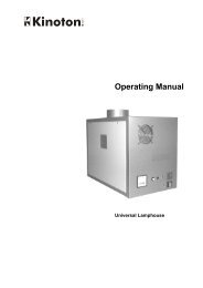
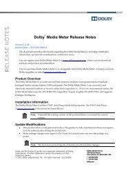
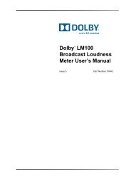
Advanced FeaturesAdvanced MIDI FeaturesGeneral FeaturesMIDI Setup MenuWith Micro Lynx software version 1.30 and later, the MIDIcapabilities were enhanced for more versatile operation. These<strong>features</strong> and the MIDI Setup Menu are described in this section.• User selectable MIDI MTC input source.• MTC to LTC conversion.• MIDI translator - 5-pin to 8-pin MAC feature.• Comprehensive MIDI data and MTC routing matrix.• MTC to digital audio word clock workstation resolve function.• MIDI time code as master is now implemented. This allowsMicro Lynx group slaves to case lock to incoming MTC.Table 9-1 is a complete list of the Micro Lynx setup options forMIDI. Figure 9-1 is a block diagram of the MIDI routing.Explanation for each menu item is also included.Press the [SETUP] key to enter setup mode. The SETUP LED willflash. Next press the [MIDI] key. After modifying the selected options,exit setup mode by pressing [SETUP] a second time. Eachmenu can be accessed directly by selecting it numerically, or sequentiallyby pressing the [LAST] and [NEXT] keys. The individualoptions are stepped through by pressing the [+] and [–] keys.Table Chapter 9 -1. Micro Lynx MIDI Setup SelectionsKEY MENU SUB-MENU RANGEMIDI MIDI Options 0 MIDI Out Jack Off, MTC, MIDI Data,MTC + Data, I/F Thru1 I/F Out Jack Off, MTC, MIDI Data,MTC + Data, MIDI Thru2 MAC Out Jack Off, MTC, MIDI Data,MTC + Data3 MIDI Thru Jack MIDI In, MIDI Out4 MTC Source MIDI In Jack, I/F Jack, MACJack5 MIDI Data Src MIDI In Jack, I/F Jack,I/F Jack6 MIDI Resolve Off, ACG ServoMicro Lynx06/22/00 9-11
Advanced FeaturesDescription Of SettingsPlease note that MIDI time code output from the Micro Lynx is afunction of the time code generator. You must group the TCGwith the other machines in the group for MTC output.Midi Out JackI/F Out JackMAC Out JackMIDI Thru JackMTC SourceMIDI Data SourceOff. Connector will not output any signal.MTC. Connector will output MIDI time code.MIDI Data. Connector will output Micro Lynx MIDI data. (Notavailable at this time.)MTC + Data. Connector will output MIDI time code and MIDIdata simultaneously. (Not available at this time.)IF/Thru. Connector will thru put MIDI information that has beeninput to the 8-pin I/F connector.Off. Connector will not output any signal.MTC. Connector will output MIDI time code.MIDI Data. Connector will output Micro Lynx MIDI data. (Notavailable at this time.)MTC + Data. Connector will output MIDI time code and MIDIdata simultaneously. (Not available at this time.)MIDI Thru. Connector will thru put data that has been input tothe 5-pin MIDI input connector.Off. Connector will not output any signal.MTC. Connector will output MIDI time code.MIDI Data. Connector will output Micro Lynx MIDI data. (Notavailable at this time.)MTC + Data. Connector will output MIDI time code and MIDIdata simultaneously. (Not available at this time.)MIDI In. MIDI thru jack outputs data from MIDI In jack.MIDI Out. MIDI thru jack outputs MIDI out data.MIDI In Jack. MIDI time code source is the MIDI In jack.I/F Jack. MIDI time code source is the I/F jack.MAC Jack. MIDI time code source is the MAC jack.MIDI In Jack. MIDI data source is the Midi In jack.I/F Jack. MIDI data source is the I/F jack.MAC Jack. MIDI data source is the MAC jack.Micro Lynx9-12 06/22/00
Advanced FeaturesMIDI DATA SRCSWITCHMIDI DATA(FOR FUTURE USE)MIDI INMTC SOURCESWITCHMIDI TIME CODEREADEROFFMIDI INPUTMIDI OUTMIDI OUT JACKSWITCHMIDI THRU/OUTMIDI THRU JACKSWITCHMIDI OUTPUTI/F INOFFMIDI TIME CODEGENERATORI/F OUTI/F OUT JACKSWITCHMIDI TIME CODEAND MIDI DATA MERGE(FOR FUTURE USE)OFFMIDI DATA(FOR FUTURE USE)MAC OUT JACKSWITCHES BUS INPUTMAC INPORT SELECTSWITCHMAC OUTES BUS OUTPUTCOMP INOFFCOMP OUTOFFNOTE:SWITCHES SHOWN INDEFAULT POSITIONSMIK083AFigure Chapter 9 -1. MIDI RoutingMicro Lynx06/22/00 9-13
Advanced FeaturesOther Setting DescriptionsThe following settings are relevant to the System Setup covered inthe Keyboard Controller section.Port Select MACMIDI. MAC port will accept MIDI or MTC input.ES. MAC port will accept ES Bus communications.Port Select RS422ES. RS422 connector will accept RS422 serial communications.Off. RS422 connector is turned off.Micro Lynx9-14 06/22/00
Advanced FeaturesUsing Mediasound with the Micro LynxIntroductionThe Micro Lynx is a synchronizer that allows you to control up tothree machines. It also generates locked SMPTE, EBU, and MIDItime codes. The Micro Lynx is composed of a system unit and akeyboard controller.The Micro Lynx reads SMPTE or EBU time code from the VTR orATR (drop frame or non-drop frame), converts it to MIDI TimeCode (MTC), and sends it to the SGI workstation serial port 2.The Micro Lynx also generates sample clock information that islocked to the tape machine speed references, and sends it to thedigital I/O port on the SGI workstation.The Micro Lynx Keyboard Controller is the system controller forthe external machine and the Mediasound Transport on the SGIworkstation. When Mediasound is in Chase mode, the Micro LynxPlay or Stop buttons operate the external machine and the SGIworkstation at the same time:! When the Micro Lynx is playing forward at normal play speed,Mediasound synchronizes to it and begins to play.! When the Micro Lynx stops, Mediasound locates to the timedisplayed in the MIDI Time Code Display (MTC in the GroupControl Area).Micro Lynx Options Necessary for Video SyncAs a slave, the SGI workstation chases the VTR/ATR master andalways locates to the point that the Micro Lynx MIDI time codestream stops. If you rewind the VTR/ATR to cue to a particularframe, the Mediasound Transport jumps to the point where theVTR/ATR stops.To properly lock to video, two Micro Lynx options are required:! ACG (<strong>Audio</strong> Clock Generator). The ACG card is asynchronized digital audio sampling clock interface. It outputsdigital audio sample rate clocks that are synchronized to thesystem reference. The clock card takes video frameinformation (black burst or composite sync) and converts it toaudio clock signals. The AES/EBU output of this card isplugged into the digital I/O port on the SGI workstation.! VSG (Video Sync Generator). The VSG card is a sync pulsegenerator that outputs NTSC or PAL composite sync. Thissignal is typically routed to the External Sync inputs of videodecks in the system.Micro Lynx06/22/00 9-15
Advanced FeaturesUsing Mediasound with the Micro LynxFor information on installing a Micro Lynx and an external VTRor ATR to the SGI workstation, see Using Mediasound with theMicro Lynx later in this <strong>chapter</strong>. Detailed instructions for usingthe Micro Lynx are in the Micro Lynx manual.The Micro Lynx synchronizer includes special support forMediasound. Using the Micro Lynx with Mediasound will enableyou to control Mediasound with external video or tape decks. TheMicro Lynx also allows you to output the Mediasound time codeposition (LTC) when Mediasound is in Chase mode, and slaveMediasound to an external time code source.This section outlines the basic steps necessary to connect theMicro Lynx to Mediasound, and use it to control the workstationwith one or multiple decks. It is assumed that you are familiarwith operating the Micro Lynx or that you have read the GettingStarted section of the Micro Lynx User’s Manual. If you are notalready familiar with the Micro Lynx, read the manual before youattempt to use the Micro Lynx with Mediasound.The Micro Lynx machine control system has a number of special<strong>features</strong> that make it ideal for use with Mediasound digital audiosoftware running on SGI workstations.! The MIDI and SMPTE time code generators can besynchronized with the tape machine group, operating as avirtual tape machine that chases the reference machine timecode numbers.! If the MTC output is connected to the serial port on the SGIworkstation running Mediasound, the workstation will run asif it were a slave tape machine.! Mediasound is similar to a video tape machine in that it usestime code (in this case MIDI time code) for positionalsynchronization. However, when Mediasound is in play, itreleases to an external AES/EBU digital audio reference,which then controls its speed and position.! The Micro Lynx is specifically designed to generate a digitalaudio clock reference for digital workstations. The <strong>Audio</strong> ClockGenerator Card (ACG-2) generates locked, digital audio clocksignals to control the play speed or sample rate of digitalequipment.Micro Lynx9-16 06/22/00
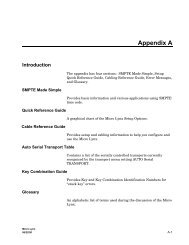
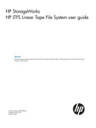
Advanced Features! If the Micro Lynx is equipped with a VITC Option Card, it willupdate the MIDI time code position for Mediasound in jog,shuttle and still modes, from VITC striped on the video tape.This allows an accurate method of spotting current VITCframe numbers to Mediasound for sound effects and postproduction work.Unless the feature is specifically disabled, Mediasound isautomatically configured for correct operation by the Micro Lynxwhen Mediasound is put into Chase mode. The following optionsare initialized by the Micro Lynx:! The time code type: 24 (film), 25 (EBU), 30 Drop, or Non Drop(SMPTE) codes.! The system frame rate: 24, 25, 29.97, or 30 frames per second.! The sample rate: 32.000, 44.100, or 48.000 kHz. If an NTSC0.1%pull down is selected, the sample rates will be 31,968, 44,056,and 47,952 kHz. Non-standard and variable rates can also beset.To complete the system configuration, you need to select the typeof video or tape transport to be controlled by the Micro Lynx.Figure Chapter 9 -2. Micro Lynx with an SGI WorkstationMicro Lynx06/22/00 9-17
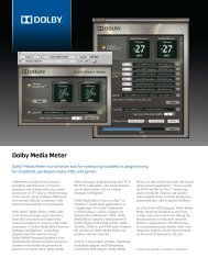
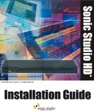
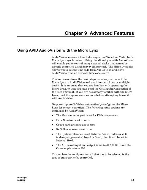
MADE IN USAAdvanced FeaturesMicro Lynx to Computer Connections! Connect the ACG AES/EBU output to the SGI workstationDigital I/O jack, using the supplied cables.Note: The workstation’s digital audio output is available atthe unattached plug of the supplied “Y” cable.! Connect a standard Macintosh printer cable (supplied)between the SGI workstation Serial Port 2 and the Micro LynxMIDI I/F connector.MICRO LYNX BACK PANELS/NTIME CODERDR 1 RDR 2 OUT AUX IN AUX OUTINMIDIOUT THRU/OUT I/F MACCOMPUTERRS232/422 SYSTEM TALLYAUDIO CLOCK GENERATORAES/EBUO.S. OUT WORD OUT CLOCK INPOWERVIDEO REFTRANSPORT 1 TRANSPORT 2SGI WORKSTATIONBACK PANELKEYBOARD8-PINMINI-DININVITCTHRURDR 39-PINTRANSPORT 3MDS001RCA MALERCA FEMALEBLACKSGI DIGITAL INPUTSGI DIGITALINPUT/OUTPUTSGI SERIALPORTDIGITAL23.5MM STEROMINIPHONE8-PINMINI-DINSGI DIGITAL OUTPUTTO DAT, ETC.RCA FEMALEREDFigure Chapter 9 -3. Micro Lynx to SGI Workstation ConnectionsMicro Lynx9-18 06/22/00
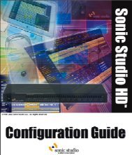
SETUPSYS TRAN EVNTLOCKBUSYRECLOCKBUSYRECA B CGRPLOCDEVICE SELECTACGF1LOCKBUSYRECF2LISTGROUP SELECTTCGF3MEMMIDISOLO LOOP RDY TRKSCUEALLSTOPMOTIONRCLCALCULATORSTOASM7 8 9IN OUT DURA4 CUE TC4 5 6SYNCP OFST ERRA1 A2 A31 2 3PRE POST REFVID0 CLR 00TIMEROLLBACKACGREPLAYREHOPTIONSMIDICOMPUTER KEYBOARDSYSTEMVITC M3 DATA VALID DATA VALID DATA VALID DATA VALID ONMACROCAPT=+–SUBFREDITRECINREFLOCK1600 (48K)1920OUTMicro Lynx KeyboardSTATUSSYSTEMMIXEDCODEVIDEOGEN1470 NON+ (44.1K)1764 STD /–DIGITAL AUDIO CLOCK GENERATORLAST NEXT ENTRTRIM JOG SHTLJOG WHEELVITCPOWERAdvanced FeaturesMicro Lynx to VTR Connections (Typical)The Micro Lynx is compatible with many video transports thatsupport external synchronization, including standard 3/4-inch U-matic, Beta, S-VHS, VHS, open reel, and digital VTRs. With aMicro Lynx, the video machines are always resolved, so they canbe run as either Master or Slave. If the VTR uses Sony SerialProtocol, serial time code can be used as the time code source.Use an external video sync source as a speed reference source forthe Micro Lynx and VTR. Install the Micro Lynx Video SyncGenerator Card (VSG), if an external sync source is not available.ATR (DTR)VTRSYNCSYNCCONTROLTIME CODECONTROLTIME CODESYNCVSGEXT SYNCTimeLine Micro Lynx System UnitMICRO LYNXSYSTEM UNITTIME CODE GENERATORRS422POWER SUPPLYTimeLineMDS002AMICRO LYNXKEYBOARD CONTROLLERFigure Chapter 9 -4. Micro Lynx to VTR ConnectionsMicro Lynx06/22/00 9-19
Advanced FeaturesMicro Lynx Setup<strong>Audio</strong> Clock Generator SetupThe AES/EBU <strong>Audio</strong> Clock Generator produces a digital audio bitstream locked to the Micro Lynx system reference. Thisinformation is used by the SGI workstation to control the playspeed of the digital audio.Set the desired sample rate using the Nominal S/Rate Out sectionof the SETUP ACG Menu. When Mediasound is in Chase mode, itautomatically detects and adjusts to this setting.On the Micro Lynx Keyboard press the [SETUP] key followed bythe [ACG] key. These two keys are next to each other in the topleft corner of the keyboard. Pressing [SETUP] puts the MicroLynx into setup mode, which is used to configure the system. The[Last/Next] keys are used to step through setup options and the[+/-] keys are used to select the required parameters.Note: In the following instructions, it is not necessary to exitsetup mode after each step.ProcedureSet the system sample rate.1. [SETUP], [ACG]2. [+/-]Setup: ACG OptionsSelection: NOM S/Rate Out 44.100 ks/sYou are in the ACG Setup Menu.Use to select the correct sample rate.3. [SETUP]Exit Setup mode.Set the ACG variable rate output option to Off.Procedure1. [SETUP], [ACG]Setup: ACG OptionsSelection: NOM S/Rate Out 44.100 ks/sSelect ACG setup.Micro Lynx9-20 06/22/00
Advanced Features2. [Last]/[Next]3. [+/-]Setup: ACG OptionsSelection: Var Ratio Out: OffUse to turn Variable Ratio Output off.4. [SETUP]Exit Setup mode.MIDI Time Code SetupThe Micro Lynx generates MIDI time code (MTC), which is usedby Mediasound for positional synchronization. MTC can betransmitted from either the Micro Lynx MAC or MIDI I/F ports.Set the appropriate MIDI port to Output MTC.Procedure1. [SETUP], [MIDI]Setup: MIDISelection: MIDI OUT Jack: MTCSelect MIDI port setup.2. [Last]/[Next]3. [Last]/[Next]4. [+/-]Setup: MIDISelection: I/F Out Jack: MTCSetup: MIDISelection: MAC OUT Jack: MTCSelect the port you wish to use for MTC.Use to select MTC as the MIDI output.5. [SETUP]Exit Setup mode.Micro Lynx06/22/00 9-21
Advanced FeaturesMIDI Data Source SetupSystem Reference SetupThe Micro Lynx is switched by Mediasound to transmit the timecode type, frame rate and sample rate with the MTC over theMIDI port. The correct port must be selected.Set the MIDI Data Source to the same MIDI port that wasselected in the previous step.Procedure1. [SETUP], [MIDI]Setup: MIDISelection: MIDI OUT Jack: MTCSelect MIDI port setup.2. [Last]/[Next]3. [+/-]Setup: MIDISelection: MIDI Data Src: MAC JackSelect the MIDI Data Source option.Setup: MIDISelection: MIDI Data Src: I/F JackUse to select chosen port for MIDI Data Source.4. [SETUP]Exit Setup mode.The Micro Lynx system reference is used to set the reference timebase for all of the equipment in the system. If you are using avideo tape transport that is connected to an external video syncgenerator, connect the sync source to the Micro Lynx and selectExtVid as the system reference. Otherwise, select IntFix. TheMicro Lynx has an internal video sync generator (VSG) that ituses when no external video sync is available.Set the system reference for your specific application. The ACGoutput and each of the tape machines in the system will lock tothe selected system reference, which ensures correctsynchronization.Micro Lynx9-22 06/22/00
Advanced FeaturesProcedure1. [SETUP], [TCG]Setup: TCG OptionsSelection: System Ref:IntFix2. [+/-]Setup: TCG OptionsSelection: System Ref:ExtVidTime Code Generator SetupSelect the system reference required.3. [SETUP]Exit Setup mode.Setting Time Code Generator System Speed/Code TypeThe Micro Lynx time code generator is used to set the system codetype and frame rate. The options are set according to the type ofwork you are doing. If you are working with NTSC video, set thesystem code to 29.97 Hz/30. Consult the Micro Lynx Manual formore detailed description of the code types and rate options.Set the required frame rate and code type in the Micro Lynx TCGSetup options menu. When Mediasound is in Chase mode, itautomatically detects and adjusts to this setting.Procedure1. [SETUP], [TCG]Setup: TCG OptionsSelection: System Ref:IntFixSelect time code generator setup.2. [LAST/NEXT]3. [+/-]Setup: TCG OptionsSelection: System Spd/Code: 29.97 Hz/30Select system Speed/Code option.Select the frame rate and code type. These options should be the same as thecode type and rate you want to use in Mediasound.4. [SETUP]Exit Setup mode.Micro Lynx06/22/00 9-23
Advanced FeaturesSetting Time Code Generator ModeYou also need to set the generator mode in Micro Lynx TCG Setupoptions menu. This setting ensures that time code will betransmitted to Mediasound when the attached video transport isjogging or shuttling.Procedure1. [SETUP], [TCG]Setup: TCG OptionsSelection: System Ref:IntFixSelect time code generator setup.2. [LAST/NEXT]3. [+/-]Setup: TCG OptionsSelection: TCG Group Mode: Play, MuteSelect the Group Mode option.Setup: TCG OptionsSelection: TCG Group Mode: Play, WindSelect the Play/Wind mode.4. [SETUP]Exit Setup mode.Note: The Micro Lynx remembers the settings you programmed.After powering down, you do not need to repeat the setup stepsevery time you use the system.Micro Lynx OperationControlling Mediasound with the Micro Lynx1. Put Mediasound into Chase mode by clicking the Chase buttonin the Group Display Area.2. On the Micro Lynx press [SOLO], then the [TCG] group selectkey.3. Use the Micro Lynx calculator keypad to enter the programstart time and press [STORE] [TIME] to enter a TCG starttime.4. Pressing the [PLAY] key starts the Micro Lynx time codegenerator (TCG) and transmits MIDI time code forMediasound to chase.Micro Lynx9-24 06/22/00
Advanced FeaturesControlling One Transport Device with the Micro Lynx1. With all of the hardware powered down, connect a machinecontrol cable and a time code cable between the Micro Lynxand the deck you want to control. The machine control cablegoes from the Micro Lynx’s Transport 1 connector to the deck’sremote control input. The time code cable goes from the deckto the RDR 1 input on the Micro Lynx.2. Connect a video sync source to the Video Ref port on the MicroLynx and to the video machine you are controlling. If you donot have an external video sync source, connect the Micro LynxVideo Ref port to the VTR ref input and see step 6 below.Analog audio tape transports do not require the video syncconnection.3. Turn on the Micro Lynx.4. On the Micro Lynx Keyboard, the group select keys will flash.Press machine key [A].5. Next, you need to specify the type of machine you are using.Enter setup mode by pressing the [SETUP] key on the MicroLynx keyboard. Press the [TRAN] key to select the type ofmachine you are going to synchronize. Use the [Next/Last]and [+/-] keys to select the correct type of machine from themenu.Note: If your deck does not appear in the menu, refer to theMicro Lynx Manual Appendix, Table 2, for alternate choices.6. The Micro Lynx has an internal video sync source. If you didnot connect an external video sync source in step 2, press the[TCG] key and use the [Next/Last] and [+/-] keys to set theSystem Ref option to IntFix and the Video Sync Gen option toOn.7. Press the [SETUP] key to leave setup mode.8. You are now ready to synchronize the Transport toMediasound.9. Put Mediasound into Chase mode by clicking the Chase buttonin the Group Display Area.10. On the Micro Lynx, press and hold the [Group] key and pressthe [A] and [TCG] group select keys. This forms a group of theTransport and Mediasound.11. Press [PLAY]. The Transport and Mediasound will play andsynchronize.Micro Lynx06/22/00 9-25
Advanced Features12. The Micro Lynx generator will always jam to the incomingreader code. The time code generator operation mode shouldbe set to Play/Wind to follow group transport operation. Referto TCG Option Menu in the Keyboard Controller section of theMicro Lynx Manual for option setting choices.Note: When the TCG is put in the group or put into play, MTCwill be transmitted from the selected, MIDI I/F or MACconnectors.Micro Lynx9-26 06/22/00