Welcome to Sonic DVD Creator - Audio Intervisual Design, Inc.
Welcome to Sonic DVD Creator - Audio Intervisual Design, Inc.
Welcome to Sonic DVD Creator - Audio Intervisual Design, Inc.
- No tags were found...

Create successful ePaper yourself
Turn your PDF publications into a flip-book with our unique Google optimized e-Paper software.
<strong>Sonic</strong> <strong>DVD</strong> Crea<strong>to</strong>rTMInstallation Guide
©1999 <strong>Sonic</strong> Solutions. All rights reserved.<strong>Sonic</strong> <strong>DVD</strong> Crea<strong>to</strong>r Installation Guide - <strong>Sonic</strong> Part Number 800114 Rev E (12/99)This manual, as well as the software described in it, is furnished under license and may only be used or copied inaccordance with the terms of such license. The information in this manual is furnished for informational use only, issubject <strong>to</strong> change without notice, and should not be construed as a commitment by <strong>Sonic</strong> Solutions. <strong>Sonic</strong> Solutionsassumes no responsibility or liability for any errors or inaccuracies that may appear in this book.Except as permitted by such license, no part of this publication may be reproduced, s<strong>to</strong>red in a retrieval system, ortransmitted, in any form or by any means, electronic, mechanical, recording, or otherwise, without the prior writtenpermission of <strong>Sonic</strong> Solutions.SONIC SOLUTIONS, INC. ("SONIC") MAKES NO WARRANTIES, EXPRESS OR IMPLIED, INCLUDING WITHOUTLIMITATION THE IMPLIED WARRANTIES OF MERCHANTABILITY AND FITNESS FOR A PARTICULAR PURPOSE,REGARDING THE APPLE SOFTWARE. SONIC DOES NOT WARRANT, GUARANTEE, OR MAKE ANYREPRESENTATIONS REGARDING THE USE OR THE RESULTS OF THE USE OF THE SONIC SOFTWARE IN TERMSOF ITS CORRECTNESS, ACCURACY, RELIABILITY, CURRENTNESS, OR OTHERWISE. THE ENTIRE RISK AS TO THERESULTS AND PERFORMANCE OF THE SONIC SOFTWARE IS ASSUMED BY YOU. THE EXCLUSION OF IMPLIEDWARRANTIES IS NOT PERMITTED BY SOME STATES. THE ABOVE EXCLUSION MAY NOT APPLY TO YOU.IN NO EVENT WILL SONIC, ITS DIRECTORS, OFFICERS, EMPLOYEES, OR AGENTS BY LIABLE TO YOU FOR ANYCONSEQUENTIAL, INCIDENTAL, OR INDIRECT DAMAGES (INCLUDING DAMAGES FOR LOSS OF BUSINESSPROFITS, BUSINESS INTERRUPTION, LOSS OF BUSINESS INFORMATION, AND THE LIKE) ARISING OUT OF THEUSE OR INABILITY TO USE THE APPLE SOFTWARE EVEN IF SONIC HAS BEEN ADVISED OF THE POSSIBILITY OFSUCH DAMAGES. BECAUSE SOME STATES DO NOT ALLOW THE EXCLUSION OR LIMITATION OF LIABILITYFOR CONSEQUENTIAL OR INCIDENTAL DAMAGES, THE ABOVE LIMITATIONS MAY NOT APPLY TO YOU.<strong>Sonic</strong>, <strong>Sonic</strong> Solutions, the <strong>Sonic</strong> logo, <strong>Sonic</strong>Studio, <strong>Sonic</strong> <strong>DVD</strong> Crea<strong>to</strong>r, <strong>DVD</strong> Ready, Constant Q and High-Density<strong>Audio</strong> are trademarks of <strong>Sonic</strong> Solutions.NoNOISE is a registered trademark of <strong>Sonic</strong> Solutions.Dolby Digital is a trademark of Dolby Labora<strong>to</strong>ries, <strong>Inc</strong>.Dolby Labora<strong>to</strong>ries encourages use of the Dolby Digitaltrademark <strong>to</strong> identify soundtracks that are encoded in Dolby Digital. This is an effective way <strong>to</strong> inform listeners of thesoundtrack format, and the use of a standard logo promotes easy recognition in the marketplace. However, like anytrademark, the Dolby Digital logo may not be used without permission. Dolby Labora<strong>to</strong>ries therefore provides astandard trademark license agreement for companies who wish <strong>to</strong> use Dolby trademarks. This agreement should besigned by the company that owns the program material being produced. Recording studios or production facilitieswhich provide audio production or encoding services for outside clients generally do not require a trademark license. Ifyou would like more information on obtaining a Dolby trademark license, please contact Dolby Labora<strong>to</strong>ries LicensingCorporation. Information on trademark licensing plus instructions for using the Dolby Digital trademark and markingaudio formats can also be found online at http://www.dolby.com.Apple, the Apple logo, Finder, Macin<strong>to</strong>sh and Quicktime are registered trademarks of Apple Computer, <strong>Inc</strong>.Acrobat and Pho<strong>to</strong>shop are trademarks of Adobe Systems, <strong>Inc</strong>.All other company or product names are either trademarks or registered trademarks of their respective owners.Written and designed at <strong>Sonic</strong> Solutions, 101 Rowland Way, Nova<strong>to</strong>, CA. 94945, USA
ContentsWELCOME TO SONIC <strong>DVD</strong> CREATORAudience . . . . . . . . . . . . . . . . . . . . . . . . . . . . . . . . . . . . . . . . . . . . .vRelated User Documentation . . . . . . . . . . . . . . . . . . . . . . . . . . . . viHow <strong>to</strong> Reach Technical Support . . . . . . . . . . . . . . . . . . . . . . . . . viActivating the <strong>Sonic</strong> Key File. . . . . . . . . . . . . . . . . . . . . . . . . . . . .viiRetrieving Your Activa<strong>to</strong>r Code . . . . . . . . . . . . . . . . . . . . . . .viiActivating Your Keyfile . . . . . . . . . . . . . . . . . . . . . . . . . . . . . . ix1 <strong>DVD</strong>-5400 HARDWARE INSTALLATION<strong>DVD</strong>-5400 Installation Quick Start. . . . . . . . . . . . . . . . . . . . . . . . 1-2What’s <strong>Inc</strong>luded with the <strong>DVD</strong>-5400 System . . . . . . . . . . . . . . . 1-3System Requirements. . . . . . . . . . . . . . . . . . . . . . . . . . . . . . . . . 1-4Installing the Hardware . . . . . . . . . . . . . . . . . . . . . . . . . . . . . . . . 1-5Installing the PCI Bridge Card in the Macin<strong>to</strong>sh . . . . . . . . . 1-5About SCSI Accelera<strong>to</strong>r Cards . . . . . . . . . . . . . . . . . . . . . . . 1-7Connecting the Media Drive <strong>to</strong> the Macin<strong>to</strong>sh . . . . . . . . . . 1-7Installing the Cards in the Expansion Chassis . . . . . . . . . . . 1-9Connecting the Expansion Chassis <strong>to</strong> the Macin<strong>to</strong>sh . . . . . . . 1-13Connecting the AV Processor <strong>to</strong> the AV I/O . . . . . . . . . . . . 1-14
IIT ABLE OF C ONTENTSConnecting the AV I/O <strong>to</strong> the <strong>Sonic</strong> <strong>Audio</strong> I/O . . . . . . . . . . 1-15Connecting the High-Density <strong>Audio</strong> I/O . . . . . . . . . . . . . 1-16Connecting Timecode and Machine Control. . . . . . . . . . . 1-17Where To Go Next . . . . . . . . . . . . . . . . . . . . . . . . . . . . . . . . . . . 1-192 <strong>DVD</strong>-5300 HARDWARE INSTALLATION<strong>DVD</strong>-5300 Installation Quick Start . . . . . . . . . . . . . . . . . . . . . . . 2-2What’s <strong>Inc</strong>luded with the <strong>DVD</strong>-5300 System . . . . . . . . . . . . . . . 2-3System Requirements. . . . . . . . . . . . . . . . . . . . . . . . . . . . . . . . . 2-4Installing the Hardware. . . . . . . . . . . . . . . . . . . . . . . . . . . . . . . . 2-5Installing the PCI Bridge Card in the Macin<strong>to</strong>sh . . . . . . . . . 2-5About SCSI Accelera<strong>to</strong>r Cards . . . . . . . . . . . . . . . . . . . . . . . 2-7Connecting the Media Drive <strong>to</strong> the Macin<strong>to</strong>sh . . . . . . . . . . 2-7Installing the Cards in the Expansion Chassis. . . . . . . . . . . 2-9Connecting the Expansion Chassis <strong>to</strong> the Macin<strong>to</strong>sh. . . . 2-13Connecting the AV Processor <strong>to</strong> the AV I/O . . . . . . . . . . . . 2-14Connecting the AV I/O <strong>to</strong> the <strong>Audio</strong> I/O . . . . . . . . . . . . . . . 2-15Connecting Timecode and Machine Control. . . . . . . . . . . 2-16Where To Go Next . . . . . . . . . . . . . . . . . . . . . . . . . . . . . . . . . . . 2-173 <strong>DVD</strong>-5200 HARDWARE INSTALLATION<strong>DVD</strong>-5200 Installation Quick Start . . . . . . . . . . . . . . . . . . . . . . . 3-2What’s <strong>Inc</strong>luded with the <strong>DVD</strong>-5200 System . . . . . . . . . . . . . . . 3-3System Requirements. . . . . . . . . . . . . . . . . . . . . . . . . . . . . . . . . 3-4Installing the Hardware. . . . . . . . . . . . . . . . . . . . . . . . . . . . . . . . 3-5Installing the PCI Cards in the Macin<strong>to</strong>sh . . . . . . . . . . . . . . 3-5Connecting the Cards . . . . . . . . . . . . . . . . . . . . . . . . . . . . . . 3-7About SCSI Accelera<strong>to</strong>r Cards . . . . . . . . . . . . . . . . . . . . . . . 3-7Connecting the Media Drive <strong>to</strong> the Macin<strong>to</strong>sh . . . . . . . . . . 3-8Connecting the AV Processor <strong>to</strong> the AV I/O . . . . . . . . . . . . . 3-9Connecting Timecode and Machine Control. . . . . . . . . . . 3-10
T ABLE O F C ONTENTSIIIWhere To Go Next . . . . . . . . . . . . . . . . . . . . . . . . . . . . . . . . . . . 3-124 <strong>DVD</strong>-5100/5150 INSTALLATION<strong>DVD</strong>-5100/5150 Installation Quick Start . . . . . . . . . . . . . . . . . . . 4-2What’s <strong>Inc</strong>luded with the <strong>DVD</strong>-5100/5150 Systems . . . . . . . . . . 4-3System Requirements . . . . . . . . . . . . . . . . . . . . . . . . . . . . . . . . . 4-4Installing the Hardware . . . . . . . . . . . . . . . . . . . . . . . . . . . . . . . . 4-5Installing the PCI Card(s) in the Macin<strong>to</strong>sh . . . . . . . . . . . . . 4-5Connecting the Cards (<strong>DVD</strong>-5150 only) . . . . . . . . . . . . . . . . 4-7About SCSI Accelera<strong>to</strong>r Cards . . . . . . . . . . . . . . . . . . . . . . . 4-7Connecting the Media Drive <strong>to</strong> the Macin<strong>to</strong>sh. . . . . . . . . . . 4-8Connecting the AV I/O . . . . . . . . . . . . . . . . . . . . . . . . . . . . . . 4-9Connecting Timecode and Machine Control (<strong>DVD</strong>-5150) . 4-10Where To Go Next . . . . . . . . . . . . . . . . . . . . . . . . . . . . . . . . . . . 4-125 CONNECTING EXTERNAL DEVICESThe <strong>Audio</strong>-Video I/O. . . . . . . . . . . . . . . . . . . . . . . . . . . . . . . . . . . 5-2Video Moni<strong>to</strong>rs . . . . . . . . . . . . . . . . . . . . . . . . . . . . . . . . . . . 5-2Videotape Decks . . . . . . . . . . . . . . . . . . . . . . . . . . . . . . . . . . 5-3<strong>Audio</strong> Moni<strong>to</strong>ring Systems. . . . . . . . . . . . . . . . . . . . . . . . . . 5-4Front Panel Controls and Indica<strong>to</strong>rs . . . . . . . . . . . . . . . . . . . 5-5The <strong>Sonic</strong> <strong>Audio</strong> I/O . . . . . . . . . . . . . . . . . . . . . . . . . . . . . . . . . . . 5-7AC Power . . . . . . . . . . . . . . . . . . . . . . . . . . . . . . . . . . . . . . . . 5-7Analog Inputs and Outputs . . . . . . . . . . . . . . . . . . . . . . . . . . 5-8Digital Inputs and Outputs . . . . . . . . . . . . . . . . . . . . . . . . . . 5-9Computer Connections . . . . . . . . . . . . . . . . . . . . . . . . . . . . . 5-9Master Clock Source . . . . . . . . . . . . . . . . . . . . . . . . . . . . . . 5-10Front Panel Controls and Indica<strong>to</strong>rs . . . . . . . . . . . . . . . . . . 5-12The High-Density <strong>Audio</strong> I/O . . . . . . . . . . . . . . . . . . . . . . . . . . 5-13Front-Panel Indica<strong>to</strong>rs . . . . . . . . . . . . . . . . . . . . . . . . . . . . . 5-14Rear-Panel Switches & Connec<strong>to</strong>rs . . . . . . . . . . . . . . . . . . 5-15
IVT ABLE OF C ONTENTSConnections . . . . . . . . . . . . . . . . . . . . . . . . . . . . . . . . . . . . 5-16Multi-Channel Expansion . . . . . . . . . . . . . . . . . . . . . . . . . . 5-18Configuring the System . . . . . . . . . . . . . . . . . . . . . . . . . . . 5-196 INSTALLING <strong>DVD</strong> CREATORPerformance Tip: Use Moni<strong>to</strong>r with Millions of Colors . . . . . . 6-2APPENDICESATROUBLESHOOTINGTesting Video Output . . . . . . . . . . . . . . . . . . . . . . . . . . . . . . . . . A-2Testing Video Input . . . . . . . . . . . . . . . . . . . . . . . . . . . . . . . . . A-4Testing <strong>Audio</strong> Output . . . . . . . . . . . . . . . . . . . . . . . . . . . . . . . . A-5Testing <strong>Audio</strong> Inputs . . . . . . . . . . . . . . . . . . . . . . . . . . . . . . . . . A-7Testing Machine Control and Timecode . . . . . . . . . . . . . . . . . . A-8Saving Your Files . . . . . . . . . . . . . . . . . . . . . . . . . . . . . . . . . . . A-10Saving the <strong>Sonic</strong>Status Files . . . . . . . . . . . . . . . . . . . . . . . A-10Saving the TattleTech Files . . . . . . . . . . . . . . . . . . . . . . . . A-11BAUDIO CONNECTOR WIRINGAES/EBU Inputs. . . . . . . . . . . . . . . . . . . . . . . . . . . . . . . . . . . B-2AES/EBU Outputs . . . . . . . . . . . . . . . . . . . . . . . . . . . . . . . . . B-2Balanced Analog Inputs and Outputs . . . . . . . . . . . . . . . . . B-4Unbalanced Analog Inputs and Outputs . . . . . . . . . . . . . . . B-6CSAFETY INFORMATIONEquipment Safety Information . . . . . . . . . . . . . . . . . . . . . . . . . . C-2INDEX
<strong>Welcome</strong> <strong>to</strong> <strong>Sonic</strong> <strong>DVD</strong> Crea<strong>to</strong>r <strong>Welcome</strong> <strong>to</strong> <strong>DVD</strong> Crea<strong>to</strong>r from <strong>Sonic</strong> Solutions! <strong>DVD</strong> Crea<strong>to</strong>r is the only<strong>DVD</strong> production system designed as a completely integrated workgroup forcreative, streamlined <strong>DVD</strong> production. With authoring, video and audioencoding, final product proofing, and disc formatting all on a singleplatform, <strong>Sonic</strong> <strong>DVD</strong> Crea<strong>to</strong>r gives you everything you need <strong>to</strong> take aproject from initial concept <strong>to</strong> final disc image.AudienceThis manual is intended for use by post-production companies, multimediadevelopers and corporate video professionals who use <strong>DVD</strong> Crea<strong>to</strong>r as theircomplete premastering solution for preparing, encoding, authoring andformatting content for <strong>DVD</strong>.You should be familiar with basic computer terms such as click, drag,highlight, etc. We also assume that you understand the basics of how <strong>to</strong>maneuver through the Mac OS interface; if not, please review the tu<strong>to</strong>rialsprovided by Apple.
VIRelated User DocumentationThis guide focuses on installation and maintenance. Please refer <strong>to</strong> thefollowing documentation for operational information:• <strong>Sonic</strong> <strong>DVD</strong> Crea<strong>to</strong>r User Guide• <strong>Sonic</strong> <strong>DVD</strong> Crea<strong>to</strong>r Tu<strong>to</strong>rialHow <strong>to</strong> Reach Technical SupportYou will receive software technical support from <strong>Sonic</strong> Solutions for 90days at no charge. If you wish <strong>to</strong> continue receiving support or additionaltechnical assistance, please be sure <strong>to</strong> purchase a <strong>Sonic</strong>Care technicalsupport contract for your system (a representative will contact you beforethe 90-day period is up).<strong>Sonic</strong> Solution’s Cus<strong>to</strong>mer Support center is available from 6:00 AM -6:00 PM PST via phone, fax or email:Telephone: 415.893.7000 or 888.SONIC.97 (1.888.766.4297)Fax: 415.893.8008Email: dvdsupport@sonic.comPlease have the following information before contacting cus<strong>to</strong>mer support:• Software version (select the application icon and type COMMAND + I orlook on the CD-ROM label)• Board Serial Numbers - look on the board for the sticker and write theserial numbers below:MPEG-2 Encoder:AV Processor:HDSP Processor:
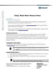
A CTIVATING T HE S ONIC K EY F ILEVIIActivating the <strong>Sonic</strong> Key FileTo enable your <strong>Sonic</strong> application, you must first generate a keyfile. In order<strong>to</strong> get you up and running with your <strong>Sonic</strong> Solutions software as quickly aspossible, we have created a World Wide Web-based keyfile activationsystem.Your keyfile is generated by the <strong>Sonic</strong> Keyfile Activa<strong>to</strong>r application, locatedin the same folder as your <strong>Sonic</strong> software. The Activa<strong>to</strong>r applicationrequires a code that you can download from the <strong>Sonic</strong> Support web site.Retrieving Your Activa<strong>to</strong>r Code1 Install your <strong>Sonic</strong> Software (see Chapter 6).2 Log on<strong>to</strong> the <strong>Sonic</strong> Support web page at support.sonic.com. You should seethis page:This page contains detailed instructions that will help you <strong>to</strong> remember thisprocedure in the future. Be sure <strong>to</strong> bookmark it for later use.
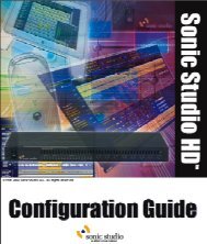
VIII3 Follow the link <strong>to</strong> the Registration Page. You should see this page:4 Enter your company name (even a portion of your company name willwork, but it helps <strong>to</strong> be precise) or your system number.5 Enter one of the board serial numbers for your system and click OK.6 You will be provided a long string of numbers and characters:This is your key activa<strong>to</strong>r code.
A CTIVATING T HE S ONIC K EY F ILEIXActivating Your KeyfileWarning! Before you activate your key code, remove from the <strong>Sonic</strong>Preferences folder (located in the System folder) any existing <strong>Sonic</strong> keyfilesthat you wish <strong>to</strong> keep. Existing keyfiles will be overwritten by your newkeyfile.1 Launch the <strong>Sonic</strong> Keyfile Activa<strong>to</strong>r application (located in the same folderas your <strong>Sonic</strong> application). You will see this dialog:Figure 1<strong>Sonic</strong> Keyfile Activa<strong>to</strong>r Dialog2 Type the Activa<strong>to</strong>r Code in<strong>to</strong> the <strong>Sonic</strong> Keyfile Activa<strong>to</strong>r application.Shortcut: Copy and paste the activa<strong>to</strong>r code from your web browserwindow in<strong>to</strong> the keyfile activa<strong>to</strong>r window.
X3 Click the OK but<strong>to</strong>n. Your keyfile(s) will au<strong>to</strong>matically be installed in a<strong>Sonic</strong> Preferences folder inside your Macin<strong>to</strong>sh System Folder.4 You may now launch your <strong>Sonic</strong> software.Please feel free <strong>to</strong> contact <strong>Sonic</strong> Solutions Cus<strong>to</strong>mer Support at415.893.7000 with any questions regarding this procedure. Be sure <strong>to</strong> haveyour <strong>Sonic</strong>Care number on hand when you call.
<strong>Audio</strong> LevelInputL R0db-1db-4db-30dbS O N I C<strong>Sonic</strong> Port<strong>Audio</strong> LevelOutputL R0db-1db-4db-30dbSYNCDual AESVideo Lock<strong>Audio</strong> LockClock SourceIn Out 192 176.4 96 88.2 48 44.1 WS DS 1-2 3-4 JA LockMETERINGIn Out In Out In Out In Out In Out In Out In Out In OutS O N I CSOLUTIONSSONIC SOLUTIONSS O N I CSOLUTIONSTM1 <strong>DVD</strong>-5400 Hardware InstallationThis chapter describes how <strong>to</strong> install the hardware for the <strong>Sonic</strong> <strong>DVD</strong>Crea<strong>to</strong>r AV Workstation (<strong>DVD</strong>-5400).<strong>Sonic</strong> <strong>Audio</strong> I/O<strong>DVD</strong> Crea<strong>to</strong>r TMDolbyD i g i t a lMulti-Channel Digital I/O Conversion SystemSOLUTIONS A B C D 1 2 3 4 5 6 7 8<strong>DVD</strong> Crea<strong>to</strong>rFigure 1-1The <strong>Sonic</strong> <strong>DVD</strong> Crea<strong>to</strong>r AV Workstation (<strong>DVD</strong>-5400)
1-2 <strong>DVD</strong>-5400 HARDWARE I NSTALLATION<strong>DVD</strong>-5400 Installation Quick StartFor detailed instructions, see “Installing the Hardware” on page 1-5.2Connect external SCSIdevices13Install the PCI Bridgecard in the Macin<strong>to</strong>sh*Install the cards in the ExpansionChassis and connectthe cards <strong>to</strong> oneanotherConnect the Expansion4 Chassis, <strong>Sonic</strong> <strong>Audio</strong> I/O,AV I/O andHD I/O* Note: For clarity, the video card and the SCSI card are not pictured.
W HAT’ S I NCLUDED W ITH T HE <strong>DVD</strong>-5400 SYSTEM 1-3What’s <strong>Inc</strong>luded with the <strong>DVD</strong>-5400 SystemHDSP ProcessorMPEG-2 VideoEncoderAV ProcessorPCI BridgePCI Expander Cable 160-Pin Cable Video Bus Cable <strong>Audio</strong> I/O CableTimecode/MachineControl Cable*HDSP <strong>Audio</strong> I/OCable*HDSP SerialAdapter Cable*Word SyncTermination Kit<strong>Sonic</strong> <strong>Audio</strong> I/O and<strong>Sonic</strong> Termina<strong>to</strong>r<strong>Sonic</strong> AV I/OHigh-Density<strong>Audio</strong> I/O and<strong>Sonic</strong> Termina<strong>to</strong>r*<strong>DVD</strong> Crea<strong>to</strong>rExpansion Chassis* These components are used by <strong>Sonic</strong>Studio HD. Refer <strong>to</strong> the <strong>Sonic</strong>Studio HD InstallationGuide for further information.
I NSTALLING T HE H ARDWARE 1-5Installing the HardwareThis section contains some grounding precautions and hardwareinstallation instructions.• Before making any connections, shut down your Macin<strong>to</strong>sh and anyperipheral equipment that is already connected <strong>to</strong> it. Never connect ordisconnect components when the power is on unless you are certainthat they are hot-swapable.• Use only 3-pin, grounded AC outlets and, if in doubt, test them beforeusing <strong>to</strong> ascertain that they are properly wired.• Never use ground-lifting adapters <strong>to</strong> defeat the earth groundconnection; this can result in a hazardous condition.• Use surge-protected outlets <strong>to</strong> prevent damage from power surges.• Where possible, connect all components <strong>to</strong> the same AC circuit; thiswill minimize the possiblity of ground voltage differentials.• Handle circuit cards by the edges only, and use the static protectionwrist band (included) <strong>to</strong> avoid damaging sensitive components.Installing the PCI Bridge Card in the Macin<strong>to</strong>shTo install the PCI Bridge card, you will need:• A #2 Phillips screwdriver• The Power Macin<strong>to</strong>sh CPU• The PCI Bridge card• The static protection wristband
I NSTALLING T HE H ARDWARE 1-7About SCSI Accelera<strong>to</strong>r CardsYour SCSI accelera<strong>to</strong>r card should be installed in slot 3 (next <strong>to</strong> thegraphics card). If it is not, carefully remove it and transfer it <strong>to</strong> slot 3. Refer<strong>to</strong> the manufacturer’s documentation for information on connecting andusing your SCSI accelera<strong>to</strong>r.Note: After you close the computer, reconnect its power cord beforecontinuing the installation. This will ensure that the computer is safelygrounded, and thus prevent damage from differing ground potentials orstray electrostatic charges.Connecting the Media Drive <strong>to</strong> the Macin<strong>to</strong>shTo connect the external Media Drive <strong>to</strong> the Macin<strong>to</strong>sh, you will need:• The Power Macin<strong>to</strong>sh CPU• A Macin<strong>to</strong>sh SCSI cable (the type of connec<strong>to</strong>r depends on the type ofMedia Drive)• A SCSI termina<strong>to</strong>r• The Media Drive (see www.sonic.com for a list of supported drives)To connect the Media Drive <strong>to</strong> the Macin<strong>to</strong>sh:1 Connect one end of the SCSI cable <strong>to</strong> the SCSI connec<strong>to</strong>r located on theback of your Media Drive, as shown in Figure 1-3.
1-8 <strong>DVD</strong>-5400 HARDWARE I NSTALLATION2 Connect the other end of the SCSI connec<strong>to</strong>r <strong>to</strong> the SCSI card in yourcomputer.Figure 1-3Connecting the Media Drive <strong>to</strong> the Macin<strong>to</strong>sh3 Connect the termina<strong>to</strong>r <strong>to</strong> the unused SCSI connec<strong>to</strong>r on the Media Drive.
I NSTALLING T HE H ARDWARE 1-9Installing the Cards in the Expansion ChassisTo install the cards in the Expansion Chassis, you will need:• A #2 Phillips screwdriver• The Expansion Chassis• The AV Processor card• The MPEG-2 Video Encoder card• The HDSP Processor card• The Video Bus ribbon cable• The static protection wristbandNote: If you’ve not already done so, write down the serial numbers forthe AV Processor, MPEG-2 Video Encoder and HDSP Processor cards in thespaces provided on page viii of this manual. You’ll need these numbers ifyou require technical support.To install the PCI cards:1 Remove the screws that secure the <strong>to</strong>p panel of the Expansion Chassis. Setthe screws and the <strong>to</strong>p panel aside.2 Remove the port access covers for slots 1 through 3.3 Put on the static protection wrist band and attach the wire <strong>to</strong> a groundedterminal.4 Remove the PCI cards one by one from their static-proof bag as you installthem. Handle the cards by their edges: don’t <strong>to</strong>uch the gold connec<strong>to</strong>rfingers or on-board components.
1-10 <strong>DVD</strong>-5400 HARDWARE I NSTALLATION5 Install the cards in the Expansion Chassis as shown in Figure 1-4.HDSP Processor(Slot 1)AV Processor(Slot 2)MPEG-2 VideoEncoder (Slot 3)Figure 1-4Expansion Chassis Card Installation6 For each card, align the connec<strong>to</strong>r fingers with the slot and press downuntil the card is seated. Install the screw in the port access panel <strong>to</strong> holdthe card in place.
I NSTALLING T HE H ARDWARE 1-117 Connect the MPEG-2 Video Encoder <strong>to</strong> the AV Processor with the video busribbon cable as shown in Figure 1-5.Video Bus Ribbon CableMPEG-2 Video EncoderAV ProcessorFigure 1-5Attaching the Video Bus Ribbon Cable
1-12 <strong>DVD</strong>-5400 HARDWARE I NSTALLATION8 Connect the AV Processor <strong>to</strong> the HDSP Processor as shown in Figure 1-6.MPEG-2 EncoderAV ProcessorHDSPProcessorFigure 1-6Connecting the AV Processor and HDSP ProcessorAt the rear of each card there are two 40-pin connec<strong>to</strong>rs that must belinked in a crossed configuration. Detach the rear connec<strong>to</strong>r from eachcard and install the cables as shown in Figure 1-6.9 Reinstall the <strong>to</strong>p cover of the Expansion Chassis. You can now take off thestatic protection wristband.
C ONNECTING T HE E XPANSION C HASSIS T O T HE M ACINTOSH 1-13Connecting the Expansion Chassis <strong>to</strong> the Macin<strong>to</strong>shTo connect the Expansion Chassis <strong>to</strong> the Macin<strong>to</strong>sh, you will need:• The Power Macin<strong>to</strong>sh CPU• The Expansion Chassis• The PCI expander cableTo connect the Expansion Chassis <strong>to</strong> the Macin<strong>to</strong>sh:1 Be sure that both devices are plugged in and turned off.2 Attach one end of the PCI expander cable <strong>to</strong> the PCI bridge card’sconnec<strong>to</strong>r on the Macin<strong>to</strong>sh.Figure 1-7Connecting the Macin<strong>to</strong>sh <strong>to</strong> the Expansion Chassis3 Attach the other end <strong>to</strong> the Expansion Chassis as shown in Figure 1-7.
1-14 <strong>DVD</strong>-5400 HARDWARE I NSTALLATIONConnecting the AV Processor <strong>to</strong> the AV I/OTo connect the AV I/O <strong>to</strong> the AV Processor, you will need:• The Expansion Chassis with cards installed• The AV I/O• The 160-pin cableTo connect the AV I/O <strong>to</strong> the AV Processor:1 Make certain that the Expansion Chassis and AV I/O are plugged in andturned off.2 Connect one end of the 160-pin cable <strong>to</strong> the corresponding connec<strong>to</strong>r onthe AV I/O as shown in Figure 1-8.3 Connect the other end <strong>to</strong> the AV Processor in the Expansion Chassis.Figure 1-8Connecting the AV I/O <strong>to</strong> the AV Processor
C ONNECTING T HE E XPANSION C HASSIS T O T HE M ACINTOSH 1-15Connecting the AV I/O <strong>to</strong> the <strong>Sonic</strong> <strong>Audio</strong> I/OTo connect the AV I/O <strong>to</strong> the <strong>Sonic</strong> <strong>Audio</strong> I/O, you will need:• The AV I/O• The <strong>Sonic</strong> <strong>Audio</strong> I/O• The <strong>Audio</strong> I/O cable• One of the <strong>Sonic</strong> Bus Termina<strong>to</strong>rsTo connect the AV I/O <strong>to</strong> the <strong>Sonic</strong> <strong>Audio</strong> I/O:1 Attach one end of the <strong>Audio</strong> I/O cable <strong>to</strong> the corresponding connec<strong>to</strong>r onthe AV I/O.Figure 1-9Connecting the AV I/O <strong>to</strong> the <strong>Audio</strong> I/O2 Now, attach the other end of the cable <strong>to</strong> the open <strong>Sonic</strong> Bus connec<strong>to</strong>r onthe back of the <strong>Sonic</strong> <strong>Audio</strong> I/O. Connect the <strong>Sonic</strong> Bus Termina<strong>to</strong>r <strong>to</strong> theunused <strong>Sonic</strong> Bus connec<strong>to</strong>r.
1-16 <strong>DVD</strong>-5400 HARDWARE I NSTALLATIONConnecting the High-Density <strong>Audio</strong> I/OTo connect the HD I/O, you will need:• The Expansion Chassis with cards installed• The HD I/O• The HDSP <strong>Audio</strong> I/O Cable• The other <strong>Sonic</strong> Bus Termina<strong>to</strong>rFigure 1-10Connecting the HD I/O
C ONNECTING T HE E XPANSION C HASSIS T O T HE M ACINTOSH 1-17To connect the HD I/O:1 Make certain that the Expansion Chassis and HD I/O are plugged in andturned off.2 Connect one end of the HDSP <strong>Audio</strong> I/O cable <strong>to</strong> the correspondingconnec<strong>to</strong>r on the HDSP Processor, located in slot 1 of the ExpansionChassis.3 Connect the other end of the cable <strong>to</strong> one of the <strong>Sonic</strong> I/O port connec<strong>to</strong>rson the HD I/O rear panel.4 Connect the termina<strong>to</strong>r <strong>to</strong> the other <strong>Sonic</strong> I/O port connec<strong>to</strong>r on theHD I/O.Connecting Timecode and Machine ControlThe <strong>DVD</strong>-5400 Workstation reads and generates timecode in the SMPTE andEBU formats. It also has the capability <strong>to</strong> control external video transports.Connections <strong>to</strong> enable these features are made through the AV I/O.To connect machine control and timecode, you will need:• The AV I/O• A standard DB-9 machine control cable (not supplied)• Optionally, an XLR-XLR cable and appropriate adapter (not supplied)• Compatible video transport
1-18 <strong>DVD</strong>-5400 HARDWARE I NSTALLATIONFigure 1-11Connecting Timecode and Machine ControlTo video deckmachine controlportTo connect timecode and machine control:1 Attach one end of the DB-9 cable <strong>to</strong> the Machine Control connec<strong>to</strong>r on therear of the AV I/O as shown in Figure 1-11.2 Connect the other end of the cable <strong>to</strong> the machine control port on thevideo deck.3 Optionally, if your video deck cannot transmit timecode through themachine control port, use an XLR-type cable and suitable adapter (ifnecessary) <strong>to</strong> connect the deck’s LTC output <strong>to</strong> the AV I/O Timecode input.
W HERE T O G O N EXT 1-19Where To Go NextFor further information on connections <strong>to</strong> the High-Density <strong>Audio</strong> I/O, refer<strong>to</strong> the <strong>Sonic</strong>Studio HD Installation Guide.See Chapter 5 for instructions on connecting third-party peripheralhardware such as video moni<strong>to</strong>rs and decks.See Chapter 6 for instructions on installing the software.
1-20 <strong>DVD</strong>-5400 HARDWARE I NSTALLATION
<strong>Audio</strong> LevelInputL R0db-1db-4db-30db<strong>Audio</strong> LevelOutputL R0db-1db-4db-30dbSYNCVideo Lock<strong>Audio</strong> LockMETERINGS O N I CSOLUTIONSSONIC SOLUTIONSS O N I CSOLUTIONSTM2 <strong>DVD</strong>-5300 Hardware InstallationThis chapter describes how <strong>to</strong> install the hardware for the <strong>Sonic</strong> Complete<strong>DVD</strong>-Video Workstation (<strong>DVD</strong>-5300).<strong>Sonic</strong> <strong>Audio</strong> I/O<strong>DVD</strong> Crea<strong>to</strong>r TMDolbyD i g i t a l<strong>DVD</strong> Crea<strong>to</strong>rFigure 2-1The <strong>Sonic</strong> Complete <strong>DVD</strong>-Video Workstation (<strong>DVD</strong>-5300)
2-2 <strong>DVD</strong>-5300 HARDWARE I NSTALLATION<strong>DVD</strong>-5300 Installation Quick StartFor detailed instructions, see “Installing the Hardware” on page 2-5.2Connect external SCSIdevices13Install the PCI Bridgecard in the Macin<strong>to</strong>sh*Install the cards in the ExpansionChassis and connectthe cards <strong>to</strong> oneanotherConnect the Expansion4 Chassis, <strong>Sonic</strong> <strong>Audio</strong> I/Oand AV I/O* Note: For clarity, the video card and the SCSI card are not pictured.
W HAT’ S I NCLUDED W ITH T HE <strong>DVD</strong>-5300 SYSTEM 2-3What’s <strong>Inc</strong>luded with the <strong>DVD</strong>-5300 SystemHDSP ProcessorMPEG-2 VideoEncoderAV ProcessorPCI BridgePCI Expander Cable HDSP I/O Cable* Video Bus Cable 160-Pin Cable<strong>Sonic</strong> BusTermina<strong>to</strong>r (2)Timecode/MachineControl Cable*Word SyncTermination KitHDSP SerialAdapter Cable68-Pin Cable <strong>Sonic</strong> AV I/O <strong>Sonic</strong> <strong>Audio</strong> I/O <strong>DVD</strong> Crea<strong>to</strong>rExpansionChassis* These components are used by <strong>Sonic</strong>Studio HD. Refer <strong>to</strong> the <strong>Sonic</strong>Studio HD InstallationGuide for further information.
2-4 <strong>DVD</strong>-5300 HARDWARE I NSTALLATIONSystem RequirementsIn addition <strong>to</strong> the hardware supplied by <strong>Sonic</strong>, you’ll need the followingcomponents:Macin<strong>to</strong>sh Computer System• Power Macin<strong>to</strong>sh G3/350, 400 or 450, or G4/350, 400 or 450• 384 MB memory minimum• ≥6 GB hard disk (internal drive)• 20-inch color moni<strong>to</strong>r• <strong>DVD</strong>-ROM drive• Mac OS 8.6 or later (Mac OS 9 required for Power Macin<strong>to</strong>sh G4)• QuickTime 4• 24-bit, 1024 x 768 color graphics card (if not supplied with the CPU)• ≥18 GB hard disk (external drive — for content)• Supported PCI SCSI card (if not supplied with the CPU)Note: For reasons of speed, all Power Macin<strong>to</strong>sh computers must befitted with a SCSI accelera<strong>to</strong>r card. For more information on SCSIconnections, see the <strong>Sonic</strong>Studio HD Configuration Guide, available athttp://www.sonic.com/html/support/pdf/SSHDconfig.pdf.Required Peripherals• <strong>Audio</strong> and video source and moni<strong>to</strong>ring equipment.• DLT or <strong>DVD</strong>-R driveNote: For the latest information regarding supported peripherals andSCSI cards, please visit <strong>Sonic</strong>’s web site at www.sonic.com.
I NSTALLING T HE H ARDWARE 2-5Installing the HardwareThis section contains some grounding precautions and hardwareinstallation instructions.• Before making any connections, shut down your Macin<strong>to</strong>sh and anyperipheral equipment that is already connected <strong>to</strong> it. Never connect ordisconnect components when the power is on unless you are certainthat they are hot-swapable.• Use only 3-pin, grounded AC outlets and, if in doubt, test them beforeusing <strong>to</strong> ascertain that they are properly wired.• Never use ground-lifting adapters <strong>to</strong> defeat the earth groundconnection; this can result in a hazardous condition.• Use surge-protected outlets <strong>to</strong> prevent damage from power surges.• Where possible, connect all components <strong>to</strong> the same AC circuit; thiswill minimize the possiblity of ground voltage differentials.• Handle circuit cards by the edges only, and use the static protectionwrist band (included) <strong>to</strong> avoid damaging sensitive components.Installing the PCI Bridge Card in the Macin<strong>to</strong>shTo install the PCI Bridge card, you will need:• A #2 Phillips screwdriver• The Power Macin<strong>to</strong>sh CPU• The PCI Bridge card• The static protection wristband
2-6 <strong>DVD</strong>-5300 HARDWARE I NSTALLATIONNote: For clarity, the video card and the SCSI card are not pictured.Figure 2-2Macin<strong>to</strong>sh card InstallationTo install the PCI Bridge card:1 Make certain that the Macin<strong>to</strong>sh power is off. Disconnect the power cord.2 Put on the static protection wrist band and attach the wire <strong>to</strong> a groundedterminal.3 Open the Macin<strong>to</strong>sh CPU (refer <strong>to</strong> the instructions that came with yourcomputer) and locate the PCI expansion slots.4 Remove the screw that secures the access cover for slot 1. Remove theaccess cover and set it aside.5 Unpack the PCI Bridge card from its static-proof bag. Handle the card by itsedges: don’t <strong>to</strong>uch the gold connec<strong>to</strong>r fingers or on-board components.6 Align the card’s connec<strong>to</strong>r fingers with the PCI slot and press down untilthe card is seated. Reinstall the screw <strong>to</strong> hold the card in place.
I NSTALLING T HE H ARDWARE 2-7About SCSI Accelera<strong>to</strong>r CardsYour SCSI accelera<strong>to</strong>r card should be installed in slot 3 (next <strong>to</strong> thegraphics card). If it is not, carefully remove it and transfer it <strong>to</strong> slot 3. Refer<strong>to</strong> the manufacturer’s documentation for information on connecting andusing your SCSI accelera<strong>to</strong>r.Note: After you close the computer, reconnect its power cord beforecontinuing the installation. This will ensure that the computer is safelygrounded, and thus prevent damage from differing ground potentials orstray electrostatic charges.Connecting the Media Drive <strong>to</strong> the Macin<strong>to</strong>shTo connect the external Media Drive <strong>to</strong> the Macin<strong>to</strong>sh, you will need:• The Power Macin<strong>to</strong>sh CPU• A Macin<strong>to</strong>sh SCSI cable (the type of connec<strong>to</strong>r depends on the type ofMedia Drive)• A SCSI termina<strong>to</strong>r• The Media Drive (see www.sonic.com for a list of supported drives)To connect the Media Drive <strong>to</strong> the Macin<strong>to</strong>sh:1 Connect one end of the SCSI cable <strong>to</strong> the SCSI connec<strong>to</strong>r located on theback of your Media Drive, as shown in Figure 2-3.
2-8 <strong>DVD</strong>-5300 HARDWARE I NSTALLATION2 Connect the other end of the SCSI cable <strong>to</strong> the SCSI card in your computer.Figure 2-3Connecting the Media Drive <strong>to</strong> the Macin<strong>to</strong>sh3 Connect the termina<strong>to</strong>r <strong>to</strong> the unused SCSI connec<strong>to</strong>r on the Media Drive.
I NSTALLING T HE H ARDWARE 2-9Installing the Cards in the Expansion ChassisTo install the cards in the Expansion Chassis, you will need:• A #2 Phillips screwdriver• The Expansion Chassis• The AV Processor card• The MPEG-2 Video Encoder card• The HDSP Processor card• The Video Bus ribbon cable• The static protection wristbandNote: If you’ve not already done so, write down the serial numbers forthe AV Processor, the MPEG-2 Video Encoder, and the HDSP Processor cardsin the spaces provided on page viii of this manual. You’ll need thesenumbers if you require technical support.To install the PCI cards:1 Remove the screws that secure the <strong>to</strong>p panel of the Expansion Chassis. Setthe screws and the <strong>to</strong>p panel aside.2 Remove the port access covers for ports 1 through 3.3 Put on the static protection wrist band and attach the wire <strong>to</strong> a groundedterminal.
2-10 <strong>DVD</strong>-5300 HARDWARE I NSTALLATION4 Install the cards in the Expansion Chassis as shown in Figure 1-4.HDSP Processor(Slot 1)AV Processor(Slot 2)MPEG-2 VideoEncoder (Slot 3)Figure 2-4Expansion Chassis Card Installation5 For each card, align the connec<strong>to</strong>r fingers with the slot and press downuntil the card is seated. Handle the cards by their edges: don’t <strong>to</strong>uch thegold connec<strong>to</strong>r fingers or on-board components.6 Install the screws in the port access panels <strong>to</strong> hold the cards in place.
I NSTALLING T HE H ARDWARE 2-117 Connect the MPEG-2 Video Encoder <strong>to</strong> the AV Processor with the video busribbon cable as shown in Figure 2-5.Video Bus Ribbon CableMPEG-2 Video EncoderAV ProcessorFigure 2-5Attaching the Video Bus Ribbon Cable
2-12 <strong>DVD</strong>-5300 HARDWARE I NSTALLATION8 Connect the AV Processor <strong>to</strong> the HDSP Processor as shown in Figure 2-6.MPEG-2 EncoderAV ProcessorHDSPProcessorFigure 2-6Connecting the AV Processor <strong>to</strong> the HDSP ProcessorAt the rear of the AV Processor and the HDSP Processor, there are two 40-pin connec<strong>to</strong>rs that must be linked. Remove one end of each cable andattach <strong>to</strong> the other card, crossing in an "X" pattern as shown in Figure 2-6.9 Reinstall the <strong>to</strong>p cover of the Expansion Chassis. You may now remove thestatic protection wristband.
I NSTALLING T HE H ARDWARE 2-13Connecting the Expansion Chassis <strong>to</strong> the Macin<strong>to</strong>shTo connect the Expansion Chassis <strong>to</strong> the Macin<strong>to</strong>sh, you will need:• The Power Macin<strong>to</strong>sh CPU• The Expansion Chassis• The PCI expander cableTo connect the Expansion Chassis <strong>to</strong> the Macin<strong>to</strong>sh:1 Be sure that both devices are plugged in and turned off.2 Attach one end of the PCI expander cable <strong>to</strong> the PCI Bridge card’sconnec<strong>to</strong>r on the Macin<strong>to</strong>sh, as shown in Figure 2-7.Figure 2-7Connecting the Macin<strong>to</strong>sh <strong>to</strong> the Expansion Chassis3 Now, attach the other end <strong>to</strong> the Expansion Chassis.
2-14 <strong>DVD</strong>-5300 HARDWARE I NSTALLATIONConnecting the AV Processor <strong>to</strong> the AV I/OTo connect the AV I/O <strong>to</strong> the AV Processor, you will need:• The Expansion Chassis with cards installed• The AV I/O• The 160-pin cableTo connect the AV I/O <strong>to</strong> the AV Processor:1 Make certain that the Expansion Chassis and AV I/O are plugged in andturned off.2 Connect one end of the 160-pin cable <strong>to</strong> the corresponding connec<strong>to</strong>r onthe AV I/O and the other end <strong>to</strong> the AV Processor as shown in Figure 2-8.3 Connect a <strong>Sonic</strong> Bus termina<strong>to</strong>r <strong>to</strong> the unused AV I/O connec<strong>to</strong>r.Figure 2-8Connecting the AV I/O <strong>to</strong> AV Processor
I NSTALLING T HE H ARDWARE 2-15Connecting the AV I/O <strong>to</strong> the <strong>Audio</strong> I/OTo connect the AV I/O <strong>to</strong> the <strong>Audio</strong> I/O, you will need:• The <strong>Audio</strong> I/O• The AV I/O• The 68-pin cable• A <strong>Sonic</strong> Bus Termina<strong>to</strong>rTo connect the AV I/O <strong>to</strong> the <strong>Audio</strong> I/O:1 Attach one end of the 68-pin cable <strong>to</strong> the corresponding connec<strong>to</strong>r on the<strong>Audio</strong> I/O.Figure 2-9Connecting the HDSP Processor <strong>to</strong> the <strong>Audio</strong> I/O2 Now, attach the other end of the cable <strong>to</strong> one of the connec<strong>to</strong>rs on theback of the AV I/O. Connect the <strong>Sonic</strong> Bus Termina<strong>to</strong>r <strong>to</strong> the unusedconnec<strong>to</strong>r on the AV I/O.Note: This configuration is used for Dolby Digital encoding. Forinstructions on connecting the <strong>Audio</strong> I/O for use with <strong>Sonic</strong>Studio HD,refer <strong>to</strong> the <strong>Sonic</strong>Studio HD Indtallation Guide.
2-16 <strong>DVD</strong>-5300 HARDWARE I NSTALLATIONConnecting Timecode and Machine ControlThe <strong>DVD</strong>-5300 Workstation reads and generates timecode in the SMPTE andEBU formats. It also has the capability <strong>to</strong> control external video transports.Connections <strong>to</strong> enable these features are made through the AV I/O.To connect machine control and timecode, you will need:• The AV I/O• A standard DB-9 machine control cable (not supplied)• Optionally, an XLR-XLR cable and appropriate adapter (not supplied)• Compatible video transportFigure 2-10Connecting Timecode and Machine ControlTo video deckmachine controlport
W HERE T O G O N EXT 2-17To connect timecode and machine control:1 Attach one end of the DB-9 cable <strong>to</strong> the Machine Control connec<strong>to</strong>r on therear of the AV I/O as shown in Figure 2-10.2 Connect the other end of the cable <strong>to</strong> the machine control port on thevideo deck.3 Optionally, if your video deck cannot transmit timecode through themachine control port, use an XLR-type cable and suitable adapter (ifnecessary) <strong>to</strong> connect the deck’s LTC output <strong>to</strong> the AV I/O Timecode input.Where To Go NextSee Chapter 5 for instructions on connecting third-party peripheralhardware such as video moni<strong>to</strong>rs and decks.See Chapter 6 for instructions on installing the software.
2-18 <strong>DVD</strong>-5300 HARDWARE I NSTALLATION
<strong>Audio</strong> LevelInputL R0db-1db-4db-30db<strong>Audio</strong> LevelOutputL R0db-1db-4db-30dbSYNCVideo Lock<strong>Audio</strong> LockMETERINGSONIC SOLUTIONSS O N I CSOLUTIONS3 <strong>DVD</strong>-5200 Hardware InstallationThis chapter describes how <strong>to</strong> install the hardware for the <strong>Sonic</strong> Basic <strong>DVD</strong>Authoring and Encoding Workstation (<strong>DVD</strong>-5200).<strong>Sonic</strong> <strong>Audio</strong> I/O<strong>DVD</strong> Crea<strong>to</strong>r TMDolbyD i g i t a lFigure 3-1The <strong>Sonic</strong> Basic <strong>DVD</strong> Authoring and Encoding Workstation(<strong>DVD</strong>-5200)
3-2 <strong>DVD</strong>-5200 HARDWARE I NSTALLATION<strong>DVD</strong>-5200 Installation Quick StartFor detailed instructions, see “Installing the Hardware” on page 3-5.2Connect external SCSIdevices1Install the PCI cardsin the Macin<strong>to</strong>sh*3Connect the <strong>Sonic</strong> AV I/O <strong>to</strong> theAV Processor* Note: For clarity, the video card and the SCSI card are not pictured.
W HAT’ S I NCLUDED W ITH T HE <strong>DVD</strong>-5200 SYSTEM 3-3What’s <strong>Inc</strong>luded with the <strong>DVD</strong>-5200 SystemThe <strong>DVD</strong>-5200 system comes with the following hardware:MPEG-2 VideoEncoderAV Processor <strong>Sonic</strong> AV I/O160-Pin Connec<strong>to</strong>rCableVideo Bus RibbonCableWord SyncTermination KitIn addition <strong>to</strong> the <strong>DVD</strong>-5200 hardware, you will need a Macin<strong>to</strong>sh andrequired peripherals (see “System Requirements” on page 3-4).
3-4 <strong>DVD</strong>-5200 HARDWARE I NSTALLATIONSystem RequirementsIn addition <strong>to</strong> the hardware supplied by <strong>Sonic</strong>, you’ll need the followingcomponents:Macin<strong>to</strong>sh Computer System• Power Macin<strong>to</strong>sh G3/350, 400 or 450, or G4/350, 400 or 450• 384 MB memory minimum• ≥6 GB hard disk (internal drive)• 20-inch color moni<strong>to</strong>r• <strong>DVD</strong>-ROM drive• Mac OS 8.6 or later (Mac OS 9 required for Power Macin<strong>to</strong>sh G4)• QuickTime 4• 24-bit, 1024 x 768 color graphics card (if not supplied with the CPU)• ≥18 GB hard disk (external drive — for content)• Supported PCI SCSI card (if not supplied with the CPU)Note: For reasons of speed, all Power Macin<strong>to</strong>sh computers must befitted with a SCSI accelera<strong>to</strong>r card. For more information on SCSIconnections, see the <strong>Sonic</strong>Studio HD Configuration Guide, available athttp://www.sonic.com/html/support/pdf/SSHDconfig.pdf.Required Peripherals• <strong>Audio</strong> and video source and moni<strong>to</strong>ring equipment.• DLT or <strong>DVD</strong>-R driveNote: For the latest information regarding supported peripherals andSCSI cards, please visit <strong>Sonic</strong>’s web site at www.sonic.com.
I NSTALLING T HE H ARDWARE 3-5Installing the HardwareThis section contains some grounding precautions and hardwareinstallation instructions.• Before making any connections, shut down your Macin<strong>to</strong>sh and anyperipheral equipment that is already connected <strong>to</strong> it. Never connect ordisconnect components when the power is on unless you are certainthat they are hot-swapable.• Use only 3-pin, grounded AC outlets and, if in doubt, test them beforeusing <strong>to</strong> ascertain that they are properly wired.• Never use ground-lifting adapters <strong>to</strong> defeat the earth groundconnection; this can result in a hazardous condition.• Use surge-protected outlets <strong>to</strong> prevent damage from power surges.• Where possible, connect all components <strong>to</strong> the same AC circuit; thiswill minimize the possiblity of ground voltage differentials.• Handle circuit cards by the edges only, and use the static protectionwrist band (included) <strong>to</strong> avoid damaging sensitive components.Installing the PCI Cards in the Macin<strong>to</strong>shTo install the PCI cards, you will need:• A #2 Phillips screwdriver• The Power Macin<strong>to</strong>sh CPU• The MPEG-2 Video Encoder card• The AV Processor card• The static protection wrist band
3-6 <strong>DVD</strong>-5200 HARDWARE I NSTALLATIONAV ProcessorMPEG-2 VideoEncoderFigure 3-2Macin<strong>to</strong>sh card InstallationTo install the PCI cards:1 Make certain that the Macin<strong>to</strong>sh power is off. Disconnect the power cord.2 Put on the static protection wrist band and attach the wire <strong>to</strong> a groundedterminal.3 Open the Macin<strong>to</strong>sh CPU (refer <strong>to</strong> the instructions that came with yourcomputer) and locate the PCI expansion slots.4 Remove the screws that secures the access covers for slots 1 and 2.Remove the access covers and set them aside.5 Unpack the AV Processor card from its static-proof bag. Handle the card byits edges: don’t <strong>to</strong>uch the gold connec<strong>to</strong>r fingers or on-board components.6 Align the card’s connec<strong>to</strong>r fingers with PCI slot 1 and press down until thecard is seated. Reinstall the screw <strong>to</strong> hold the card in place.
I NSTALLING T HE H ARDWARE 3-77 Similarly, unpack the MPEG-2 Video Encoder and install it in slot 2.Connecting the CardsConnect the MPEG-2 Video Encoder <strong>to</strong> the AV Processor with the video busribbon cable as shown in Figure 3-3.Video Bus Ribbon CableMPEG-2 Video EncoderAV ProcessorFigure 3-3Attaching the Video Bus Ribbon CableAbout SCSI Accelera<strong>to</strong>r CardsYour SCSI accelera<strong>to</strong>r card should be installed in slot 3 (next <strong>to</strong> thegraphics card). Refer <strong>to</strong> the manufacturer’s documentation for informationon connecting and using your SCSI accelera<strong>to</strong>r.
3-8 <strong>DVD</strong>-5200 HARDWARE I NSTALLATIONNote: After you close the computer, reconnect its power cord beforecontinuing the installation. This will ensure that the computer is safelygrounded, and thus prevent damage from differing ground potentials orstray electrostatic charges.Connecting the Media Drive <strong>to</strong> the Macin<strong>to</strong>shTo connect the external Media Drive <strong>to</strong> the Macin<strong>to</strong>sh, you will need:• The Power Macin<strong>to</strong>sh CPU• A Macin<strong>to</strong>sh SCSI cable and SCSI termina<strong>to</strong>r• The Media Drive (see www.sonic.com for a list of supported drives)To connect the Media Drive <strong>to</strong> the Macin<strong>to</strong>sh:1 Connect one end of the SCSI cable <strong>to</strong> the SCSI connec<strong>to</strong>r located on theback of your Media Drive, as shown in Figure 3-4.2 Connect the other end of the SCSI cable <strong>to</strong> the SCSI card in your computer3 Connect the termina<strong>to</strong>r <strong>to</strong> the unused SCSI connec<strong>to</strong>r on the Media Drive.Figure 3-4Connecting the Media Drive <strong>to</strong> the Macin<strong>to</strong>sh
I NSTALLING T HE H ARDWARE 3-9Connecting the AV Processor <strong>to</strong> the AV I/OTo connect the AV I/O <strong>to</strong> the AV Processor, you will need:• The Macin<strong>to</strong>sh CPU with cards installed• The AV I/O and termina<strong>to</strong>r• The 160-pin cableTo connect the AV I/O <strong>to</strong> the AV Processor:1 Make certain that the Macin<strong>to</strong>sh and AV I/O are plugged in and turned off.2 Connect one end of the 160-pin cable <strong>to</strong> the corresponding connec<strong>to</strong>r onthe AV I/O, and the termina<strong>to</strong>r <strong>to</strong> the other, as shown in Figure 3-5.3 Connect the other end <strong>to</strong> the AV Processor in the AV Processor.Figure 3-5Connecting the AV I/O <strong>to</strong> the AV Processor
3-10 <strong>DVD</strong>-5200 HARDWARE I NSTALLATIONConnecting Timecode and Machine ControlThe <strong>DVD</strong>-5200 Workstation reads and generates timecode in the SMPTE andEBU formats. It also has the capability <strong>to</strong> control external video transports.Connections <strong>to</strong> enable these features are made through the AV I/O.To connect machine control and timecode, you will need:• The AV I/O• A standard DB-9 machine control cable (not supplied)• Optionally, an XLR-XLR cable and appropriate adapter (not supplied)• Compatible video transportFigure 3-6Connecting Timecode and Machine ControlTo video deckmachine controlport
W HERE T O G O N EXT 3-11To connect timecode and machine control:1 Attach one end of the DB-9 cable <strong>to</strong> the Machine Control connec<strong>to</strong>r on therear of the AV I/O as shown in Figure 3-6.2 Connect the other end of the cable <strong>to</strong> the machine control port on thevideo deck.3 Optionally, if your video deck cannot transmit timecode through themachine control port, use an XLR-type cable and suitable adapter (ifnecessary) <strong>to</strong> connect the deck’s LTC output <strong>to</strong> the AV I/O Timecode input.Where To Go NextSee Chapter 5 for instructions on connecting third-party peripheralhardware such as the video moni<strong>to</strong>r and tape deck.See Chapter 6 for instructions on installing the software.
3-12 <strong>DVD</strong>-5200 HARDWARE I NSTALLATION
<strong>Audio</strong> LevelInputL R0db-1db-4db-30db<strong>Audio</strong> LevelOutputL R0db-1db-4db-30dbVideo Lock<strong>Audio</strong> LockS O N I CSOLUTIONS4 <strong>DVD</strong>-5100/5150 InstallationThis chapter describes how <strong>to</strong> install the hardware for the <strong>Sonic</strong> <strong>DVD</strong>Authoring Workstation (<strong>DVD</strong>-5100) and <strong>DVD</strong> Encoding Workstation (<strong>DVD</strong>-5150).<strong>DVD</strong> Crea<strong>to</strong>r TMDolbyD i g i t a lFigure 4-1The <strong>Sonic</strong> <strong>DVD</strong> Authoring Workstation or <strong>DVD</strong> EncodingWorkstation
4-2 <strong>DVD</strong>-5100/5150 INSTALLATION<strong>DVD</strong>-5100/5150 Installation Quick StartFor detailed instructions, see “Installing the Hardware” on page 4-52Connect externalSCSI devices1Install the card(s) inthe Macin<strong>to</strong>sh*Connect theInstall and configure3 AV I/Othe software4* Note: For clarity, the video card and the SCSI card are not pictured.
W HAT’ S I NCLUDED W ITH T HE <strong>DVD</strong>-5100/5150 SYSTEMS 4-3What’s <strong>Inc</strong>luded with the <strong>DVD</strong>-5100/5150 SystemsThe <strong>DVD</strong>-5100/5150 systems come with the following hardware:MPEG-2 VideoEncoder(<strong>DVD</strong>-5150 only)AV Processor <strong>Sonic</strong> AV I/OVideo Bus RibbonCable(<strong>DVD</strong>-5150 only)<strong>Sonic</strong> BusTermina<strong>to</strong>r160-Pin Connec<strong>to</strong>rCableIn addition <strong>to</strong> the <strong>Sonic</strong> hardware, you will need a Macin<strong>to</strong>sh and requiredperipherals (see “System Requirements” on page 4-4).
4-4 <strong>DVD</strong>-5100/5150 INSTALLATIONSystem RequirementsIn addition <strong>to</strong> the hardware supplied by <strong>Sonic</strong>, you’ll need the followingcomponents:Macin<strong>to</strong>sh Computer System• Power Macin<strong>to</strong>sh G3/350, 400 or 450, or G4/350, 400 or 450• 384 MB memory minimum• ≥6 GB hard disk (internal drive)• 20-inch color moni<strong>to</strong>r• <strong>DVD</strong>-ROM drive• Mac OS 8.6 or later (Mac OS 9 required for Power Macin<strong>to</strong>sh G4)• QuickTime 4• 24-bit, 1024 x 768 color graphics card (if not supplied with the CPU)• ≥18 GB hard disk (external drive — for content)• Supported PCI SCSI card (if not supplied with the CPU)Note: For reasons of speed, all Power Macin<strong>to</strong>sh computers must befitted with a SCSI accelera<strong>to</strong>r card. For more information on SCSIconnections, see the <strong>Sonic</strong>Studio HD Configuration Guide, available athttp://www.sonic.com/html/support/pdf/SSHDconfig.pdf.Required Peripherals• <strong>Audio</strong> and video source and moni<strong>to</strong>ring equipment.• DLT or <strong>DVD</strong>-R driveNote: For the latest information regarding supported peripherals andSCSI cards, please visit <strong>Sonic</strong>’s web site at www.sonic.com.
I NSTALLING T HE H ARDWARE 4-5Installing the HardwareThis section contains some grounding precautions and hardwareinstallation instructions.• Before making any connections, shut down your Macin<strong>to</strong>sh and anyperipheral equipment that is already connected <strong>to</strong> it. Never connect ordisconnect components when the power is on unless you are certainthat they are hot-swapable.• Use only 3-pin, grounded AC outlets and, if in doubt, test them beforeusing <strong>to</strong> ascertain that they are properly wired.• Never use ground-lifting adapters <strong>to</strong> defeat the earth groundconnection; this can result in a hazardous condition.• Use surge-protected outlets <strong>to</strong> prevent damage from power surges.• Where possible, connect all components <strong>to</strong> the same AC circuit; thiswill minimize the possiblity of ground voltage differentials.• Handle circuit cards by the edges only, and use the static protectionwrist band (included) <strong>to</strong> avoid damaging sensitive components.Installing the PCI Card(s) in the Macin<strong>to</strong>shTo install the PCI card(s), you will need:• A #2 Phillips screwdriver• The Power Macin<strong>to</strong>sh CPU• The AV Processor• The MPEG-2 Video Encoder (<strong>DVD</strong>-5150 only)• The static protection wristband
4-6 <strong>DVD</strong>-5100/5150 INSTALLATIONAV ProcessorMPEG-2 VideoEncoder (<strong>DVD</strong>-5150 only)Figure 4-2Macin<strong>to</strong>sh PCI Card InstallationTo install the PCI card(s):1 Make certain that the Macin<strong>to</strong>sh power is off. Disconnect the power cord.2 Put on the static wrist band and attach the wire <strong>to</strong> a grounded terminal.3 Open the Macin<strong>to</strong>sh CPU (refer <strong>to</strong> the instructions that came with yourcomputer) and locate the PCI expansion slots.4 Remove the screw that secures the access cover for slot 1. (If you areinstalling a <strong>DVD</strong>-5150 Workstation, also remove the screw for slot 2.)Remove the access cover(s) and set aside.5 Unpack the AV Processor from its static-proof bag. Handle the card by itsedges: don’t <strong>to</strong>uch the gold connec<strong>to</strong>r fingers or on-board components.6 Align the card’s connec<strong>to</strong>r fingers with PCI slot 1 and press down until thecard is seated. Reinstall the screw.
I NSTALLING T HE H ARDWARE 4-77 If you are installing a <strong>DVD</strong>-5150 Workstation, install the MPEG-2 VideoEncoder in slot 2.Connecting the Cards (<strong>DVD</strong>-5150 only)Connect the MPEG-2 Video Encoder <strong>to</strong> the AV Processor with the video busribbon cable as shown in Figure 4-3.Video Bus Ribbon CableMPEG-2 Video EncoderAV ProcessorFigure 4-3Attaching the Video Bus Ribbon CableAbout SCSI Accelera<strong>to</strong>r CardsYour SCSI accelera<strong>to</strong>r card should be installed in slot 3 (next <strong>to</strong> thegraphics card). Refer <strong>to</strong> the manufacturer’s documentation for informationon connecting and using your SCSI accelera<strong>to</strong>r.
4-8 <strong>DVD</strong>-5100/5150 INSTALLATIONNote: After you close the computer, reconnect its power cord beforecontinuing the installation. This will ensure that the computer is safelygrounded, and thus prevent damage from differing ground potentials orstray electrostatic charges.Connecting the Media Drive <strong>to</strong> the Macin<strong>to</strong>shTo connect the external Media Drive <strong>to</strong> the Macin<strong>to</strong>sh, you will need:• The Power Macin<strong>to</strong>sh CPU• A Macin<strong>to</strong>sh SCSI cable• A SCSI termina<strong>to</strong>r• The Media Drive (see www.sonic.com for a list of supported drives)To connect the Media Drive <strong>to</strong> the Macin<strong>to</strong>sh:1 Connect one end of the SCSI cable <strong>to</strong> the SCSI connec<strong>to</strong>r located on theback of your Media Drive, as shown in Figure 4-4.
I NSTALLING T HE H ARDWARE 4-92 Connect the other end of the SCSI cable <strong>to</strong> the SCSI card in your computer.Figure 4-4Connecting the Media Drive <strong>to</strong> the Macin<strong>to</strong>sh3 Connect the termina<strong>to</strong>r <strong>to</strong> the unused SCSI connec<strong>to</strong>r on the Media Drive.Connecting the AV I/OTo connect the AV I/O, you will need:• The Macin<strong>to</strong>sh CPU• The AV I/O and termina<strong>to</strong>r• The 160-pin cableTo connect the AV I/O:1 Make certain that the Macin<strong>to</strong>sh and AV I/O are plugged in and turned off.2 Connect one end of the 160-pin cable <strong>to</strong> a <strong>Sonic</strong> Buss connec<strong>to</strong>r on the AVI/O, and the termina<strong>to</strong>r <strong>to</strong> the other, as shown in Figure 4-5.
4-10 <strong>DVD</strong>-5100/5150 INSTALLATION3 Connect the other end <strong>to</strong> the AV Processor in the Macin<strong>to</strong>sh.Figure 4-5Connecting the AV I/OConnecting Timecode and Machine Control (<strong>DVD</strong>-5150)The <strong>DVD</strong>-5150 Workstation reads and generates timecode in the SMPTE andEBU formats. It also has the capability <strong>to</strong> control external video transports.Connections <strong>to</strong> enable these features are made through the AV I/O.To connect machine control and timecode, you will need:• The AV I/O• A standard DB-9 machine control cable (not supplied)• Optionally, an XLR-XLR cable and appropriate adapter (not supplied)• Compatible video transport
I NSTALLING T HE H ARDWARE 4-11Figure 4-6Connecting Timecode and Machine ControlTo video deckmachine controlportTo connect timecode and machine control:1 Attach one end of the DB-9 cable <strong>to</strong> the Machine Control connec<strong>to</strong>r on therear of the AV I/O as shown in Figure 4-6.2 Connect the other end of the cable <strong>to</strong> the machine control port on thevideo deck.3 Optionally, if your video deck cannot transmit timecode through themachine control port, use an XLR-type cable and suitable adapter (ifnecessary) <strong>to</strong> connect the deck’s LTC output <strong>to</strong> the AV I/O Timecode input.
4-12 <strong>DVD</strong>-5100/5150 INSTALLATIONWhere To Go NextSee Chapter 5 for instructions on connecting third-party peripheralhardware such as video moni<strong>to</strong>rs and decks.See Chapter 6 for instructions on installing the software.
5 Connecting External DevicesThis section describes how <strong>to</strong> connect video moni<strong>to</strong>rs, videotape decks,audio moni<strong>to</strong>ring systems and multi-channel sound systems or consoles <strong>to</strong>your <strong>DVD</strong> Workstation. Your Workstation connects with these devicesthrough the <strong>Sonic</strong> AV I/O, HD I/O and <strong>Audio</strong> I/O.
5-2 C ONNECTING E XTERNAL D EVICESThe <strong>Audio</strong>-Video I/OThis section covers external connections <strong>to</strong> the AV I/O and describes itsfront panel controls and indica<strong>to</strong>rs. For detailed connection information,see Appendix B, Connec<strong>to</strong>r Wiring.Video Moni<strong>to</strong>rsThe <strong>Sonic</strong> AV I/O incorporates a number of video outputs <strong>to</strong> accommodateall of the cus<strong>to</strong>mary interfaces for professional video moni<strong>to</strong>rs.R-Y/R OutB-Y/B OutY/G OutS-VHS OutComposite OutSDI OutFigure 5-1Video Moni<strong>to</strong>r Connections• Y/G, B-Y/B, R-Y/R — These BNC connec<strong>to</strong>rs deliver a componentsignal for YUV moni<strong>to</strong>rs. Sync is provided by the Composite videooutput: use an RCA-<strong>to</strong>-BNC adap<strong>to</strong>r and connect a BNC cable from theComposite output <strong>to</strong> the moni<strong>to</strong>r’s external sync input.• S-VHS — Connect S-VHS moni<strong>to</strong>rs <strong>to</strong> this output using a standard S-VHS cable.• Composite — This output provides a 1 volt P-P composite video signalfor video moni<strong>to</strong>rs. Use a video-grade RCA-<strong>to</strong>-RCA cable.• SDI — This BNC output accommodates SDI (Serial Digital Interface)moni<strong>to</strong>rs.
T HE A UDIO-VIDEO I/O 5-3Videotape DecksThe AV I/O also provides a variety of options for connecting videotapedecks.S-VHS InComposite InR-Y/R InR-Y/R OutB-Y/B OutY/G OutS-VHS OutComposite OutRef InB-Y/B InSDI InY/G InSDI OutMachine ControlInput LevelSMPTE Timecode InAnalog <strong>Audio</strong> In RAES/EBU <strong>Audio</strong> InAnalog <strong>Audio</strong> Out LOutput LevelAnalog <strong>Audio</strong> In LAnalog <strong>Audio</strong> Out RFigure 5-2Video Tape Deck Connections• Y/G, B-Y/B, R-Y/R — These BNC terminals connect YUV video signals<strong>to</strong> videotape decks.• S-VHS — Connect S-VHS video deck inputs and outputs <strong>to</strong> these usingstandard S-VHS cables.• Composite — These connec<strong>to</strong>rs handle 1 volt P-P composite videosignals. Use video-grade RCA-<strong>to</strong>-RCA cables.• SDI — These BNC connec<strong>to</strong>rs accommodate SDI (Serial DigitalInterface) D1 video signals.• Reference — This connec<strong>to</strong>r accepts blackburst genera<strong>to</strong>r or housesync signals.
5-4 C ONNECTING E XTERNAL D EVICES• Machine Control — Connect this input <strong>to</strong> the corresponding videodeck connec<strong>to</strong>r using a 9-pin RS-422 cable.• SMPTE Timecode — Connect the video deck timecode output <strong>to</strong> thisXLR-type input (pin 2 hot).• AES — This XLR-type input is for AES/EBU digital audio input signals.• Analog Left and Right — These XLR-type connec<strong>to</strong>rs handle balancedor unbalanced analog audio input signals (pin 2 hot). The maximuminput/output level is +25 dBu.• Level Controls — These controls adjust the sensitivity of the analogaudio inputs and the nominal signal level at the analog outputs.Inputs: For +4 dBu, set the control fully counterclockwise; for -10 dBv,set it fully clockwise.Outputs: For +4 dBu, set the control fully clockwise; for -10 dBv, set itfully counterclockwise.<strong>Audio</strong> Moni<strong>to</strong>ring SystemsThe AV I/O provides both analog and digital audio outputs for connections<strong>to</strong> audio moni<strong>to</strong>rs, mixers or recording equipment.S/PDIF OutputOutput LevelRight Analog OutputFigure 5-3<strong>Audio</strong> Moni<strong>to</strong>r ConnectionsLeft Analog Output
T HE A UDIO-VIDEO I/O 5-5• S/PDIF — This digital audio output can be connected <strong>to</strong> a Dolby Digitaldecoder or a digital-<strong>to</strong>-analog converter.• Analog Left and Right — These XLR-type outputs deliver balancedanalog audio signals (pin 2 hot). The maximum output level is +25 dBu.• Output Level Control — This control adjusts the nominal operatinglevel of the analog audio outputs. For +4 dBu, set the control fullyclockwise; for -10 dBv, set it fully counterclockwise.Front Panel Controls and Indica<strong>to</strong>rsA group of LEDs on the front panel of the <strong>Sonic</strong> AV I/O displays the statusof video and audio signals<strong>Audio</strong> LevelInput<strong>Audio</strong> LevelOutputVideo Lock<strong>Sonic</strong> <strong>DVD</strong> Crea<strong>to</strong>r TM<strong>Audio</strong>-Video I/OLR0db-1db-4db-30dbLR0db-1db-4db-30db<strong>Audio</strong>LockSONIC SOLUTIONSFigure 5-4The Front Panel of the AV I/O• <strong>Audio</strong> Input and Output Level — These indica<strong>to</strong>rs display the level ofaudio input and output signals. Should the 0 dB (red) indica<strong>to</strong>r light,clipping may occur and the Input or Output Level control should beadjusted <strong>to</strong> avoid unwanted dis<strong>to</strong>rtion.• <strong>Audio</strong> Lock — This indica<strong>to</strong>r displays the status of digital audio inputsignals. If there is no signal present at any digital audio input, theindica<strong>to</strong>r will be off. Yellow indicates the presence of signal, and greenindicates that the AV I/O is locked <strong>to</strong> the incoming signal clock.
5-6 C ONNECTING E XTERNAL D EVICESNote: The <strong>Audio</strong> Lock indica<strong>to</strong>r applies <strong>to</strong> digital audio inputs only. If youare using the AV I/O analog inputs, the indica<strong>to</strong>r will not light.• Video Lock — This LED indicates the status of video input signals. Ifthere is no input signal or the AV I/O is not locked <strong>to</strong> the incomingvideo, the indica<strong>to</strong>r will be red. Green indicates that the AV I/O islocked <strong>to</strong> a valid video input signal.• Power Switch — 1 is on, and 0 is off.
1-5 UNITS 1 08 S RAT E ANA 44.1k7 H TYPE ANA DWS6 H SEL IN OUTINPUTOUTPUTINPUTOUTPUTAES/EBU INPUTSAES/EBU IOUTPUTSANAL OG INPUTSANAL OG OUTPUTST HE S ONIC A UDIO I/O 5-7The <strong>Sonic</strong> <strong>Audio</strong> I/OThis section covers external connections <strong>to</strong> the <strong>Sonic</strong> <strong>Audio</strong> I/O anddescribes its front panel controls and indica<strong>to</strong>rs. For detailed connectioninformation, see Appendix B, Connec<strong>to</strong>r Wiring.ConfigurationSwitches<strong>Sonic</strong> I/OConnec<strong>to</strong>rsSONIC SOLUTIONS INTERFACE MODULECONFIGURATIONPOS. FUNCTION UP DOWNSONIC I/OAC INPUT 40 WAT TS MAXIMUMWORK CLOCKS/P DIFAC PowerInlet & FuseWord SyncIn & OutS/PDIFIn & OutAES/EBUIn & OutAnalogIn & OutFigure 5-5<strong>Sonic</strong> <strong>Audio</strong> I/O Rear Panel Controls and Connec<strong>to</strong>rsAC PowerThe <strong>Sonic</strong> <strong>Audio</strong> I/O features an IEC-type power connec<strong>to</strong>r. Set the LineVoltage selec<strong>to</strong>r switch <strong>to</strong> correspond with the nominal AC voltage used inyour studio, then connect <strong>to</strong> an appropriate AC power source.The user-accessible fuse is integral <strong>to</strong> the IEC power inlet. The fuseholderaccepts 5 x 20mm diameter fuses.• For 117VAC operation, the correct value is 1/2A, 250 VAC, slow blowing(Bussman type GDC-500MA).• For 230VAC operation, the correct value is 1/4A, 250 VAC, slow blowing(Bussman type GDC-250MA).
5-8 C ONNECTING E XTERNAL D EVICESAnalog Inputs and OutputsINPUTSConnect analog sources <strong>to</strong> the rear-panel analog inputs. The inputimpedance is 20k ohms, and the maximum input level is +25 dBu. Theseconnec<strong>to</strong>rs may be driven from a balanced or unbalanced, low-impedancesource. See Appendix B for instructions on wiring unbalanced cables.OUTPUTSConnect the analog outputs as required in your studio. These connec<strong>to</strong>rsdeliver a balanced output signal from a 320-ohm source that simulates atransformer. The maximum output level is +25 dBu. If you need <strong>to</strong> drive anunbalanced input, see Appendix B for instructions on wiring the cables.Note: Grounding pin 3 of the analog output will increase the signal levelat pin 2 by 6 dB.ANALOG SIGNAL LEVELSAt its input, the <strong>Sonic</strong> <strong>Audio</strong> I/O expects +4 dBu normal studio line levels.The internal digital gain control has sufficient reserve gain <strong>to</strong> allow you <strong>to</strong>drive the unit <strong>to</strong> full-scale digital output with signals as low as -30 dBu.When driving the <strong>Sonic</strong> <strong>Audio</strong> I/O from equipment using consumer (-10 dBV) equipment, add about 12 dB of gain:(-10.0 dBV = -7.8 dBu; +4.0 dBu - (-7.8 dBu) = 11.8 dB)At its output, the <strong>Sonic</strong> <strong>Audio</strong> I/O delivers a nominal +4 dBu studio linelevel signal.
T HE S ONIC A UDIO I/O 5-9Digital Inputs and OutputsAES/EBU Inputs — These three-pin XLR-type connec<strong>to</strong>rs conform <strong>to</strong> theAES3 1992 specification. Always begin any AES/EBU connection sequencewith Inputs 1-2, as these connec<strong>to</strong>rs are used for AES-3 sync.S/PDIF — These connec<strong>to</strong>rs accommodate consumer digital audioequipment.Word Clock — The Word Clock input accepts signals from an externalsync genera<strong>to</strong>r, and the Word Clock output is the output of the <strong>Audio</strong> I/Ointernal clock. This output may be sent <strong>to</strong> another device, such as anexternal DAC. Do not daisy-chain it <strong>to</strong> other <strong>Sonic</strong> hardware.Computer ConnectionsSONIC BUS CONNECTORSThe <strong>Sonic</strong> Bus uses 68-pin, mini D-sub connec<strong>to</strong>rs. The <strong>Sonic</strong> <strong>Audio</strong> I/Oconnects <strong>to</strong> the AV I/O via the <strong>Sonic</strong> Bus. Additional <strong>Sonic</strong> <strong>Audio</strong> I/Os maybe looped from the preceding <strong>Sonic</strong> <strong>Audio</strong> I/O. The unused <strong>Sonic</strong> Busconnec<strong>to</strong>r of the last device in the chain must be terminated.CONFIGURATION SWITCHESEach converter on the <strong>Sonic</strong> Bus must have a unique address between1 and 31. The ID is set using Configuration switches 1 through 5. Eachswitch represents a binary value, as follows:Switch #Value1 12 2
5-10 CONNECTING E XTERNAL D EVICESSwitch #Value3 44 85 16For example, <strong>to</strong> set the address <strong>to</strong> 24, the switches should be as shownhere:12345678AddressSwitchesNote: ID 0 (all switches down) is reserved for the AV Processor card, andID 1 (first switch up) is reserved for the AV I/O.The remaining rear-panel configuration switches need not be preset whenusing the <strong>Sonic</strong> <strong>Audio</strong> I/O with <strong>Sonic</strong> hardware. These functions arecontrolled using AV Setup in <strong>DVD</strong> Crea<strong>to</strong>r or in <strong>Sonic</strong>Studio HD’s <strong>Audio</strong> I/OSetup dialog.Master Clock SourceThe <strong>Sonic</strong> <strong>Audio</strong> I/O may be selected as the Master Clock source for<strong>DVD</strong> Crea<strong>to</strong>r Encode via the AV Setup dialog. Either the Word Clock inpu<strong>to</strong>r Digital Inputs 1 and 2 may be chosen as clock source.
POS. FUNCTION UP DOWN1-5 UNITS 1 08 S RAT E ANA 44.1k7 H TYPE ANA DWS6 H SEL IN OUTT HE S ONIC A UDIO I/O 5-11You can connect an external word sync genera<strong>to</strong>r <strong>to</strong> the <strong>Audio</strong> I/O WS Inusing a standard BNC-BNC cable. The <strong>Audio</strong> I/O can also deliver word syncfrom its internal system clock <strong>to</strong> other devices through its WS Outconnec<strong>to</strong>r.To loop input word sync between multiple I/O boxes, use the BNC teeincluded with the <strong>Audio</strong> I/O. The last unit in the word sync chain must beterminated. To do so, use the BNC tee and attach the termina<strong>to</strong>r (includedwith the <strong>Audio</strong> I/O) as shown in Figure 5-13BNC Termina<strong>to</strong>rSONIC SOLUTIONS INTERFACE MODULEAES/EBU INPUTSANAL OG INPUTSCONFIGURATIONSONIC I/OAC INPUT 40 WAT TS MAXIMUMWORK CLOCK S/P DIFINPUT INPUTAES/EBU IOUTPUTSANAL OG OUTPUTSOUTPUTOUTPUTBNC TeeWord Sync CableFigure 5-6Installation of BNC Termina<strong>to</strong>r on Word Sync InputRefer <strong>to</strong> the “<strong>DVD</strong> Crea<strong>to</strong>r User Guide” and the section titled “AV Setup” foradditional information.
5-12 CONNECTING E XTERNAL D EVICESFront Panel Controls and Indica<strong>to</strong>rsThis section gives an overview of the front and rear panels on the <strong>Sonic</strong><strong>Audio</strong> I/O.1 2 3 4 5 6 7 8<strong>Sonic</strong> <strong>Audio</strong> I/OSYNC44.1 KHZ46 KHZWORD CLKAES-3METERINGANALOG INDIGITAL INANALOG OUTDIGITAL OUTSONIC SOLUTIONSSync Window LED Bar Meters Metering WindowFigure 5-7<strong>Sonic</strong> <strong>Audio</strong> I/O Front Panel Controls and Indica<strong>to</strong>rs• SYNC Window — The SYNC Window displays the source of digitalaudio sync: 44.1 kHz internal, 48 kHz internal, Word Clock or AES-3digital input (inputs 1-2).• LED Meters — 15-segment LED bargraph meters display digital oranalog signal levels from either input or output. The source and modeselections are made via <strong>DVD</strong> Crea<strong>to</strong>r.• Metering Window — The Metering Window displays the source andmode of the meters: analog input, digital input, analog output anddigital output.• Power Switch — The Power switch turns the <strong>Sonic</strong> <strong>Audio</strong> I/O on andoff. | is On; O is Off.
T HE H IGH-DENSITY A UDIO I/O 5-13The High-Density <strong>Audio</strong> I/OThe HD I/O is an input/output box for connecting <strong>DVD</strong> Crea<strong>to</strong>rWorkstations equipped with <strong>Sonic</strong>Studio HD <strong>to</strong> external digital audiodevices.Housed in a single-space rack-mountable chassis, the HD I/O accommodatesup <strong>to</strong> eight channels of 24-bit digital audio at standard clock speedsranging from 44.1 kHz <strong>to</strong> 96 kHz, or two channels at 192 kHz. It featuressub-nanosecond sample reclocking and jitter annulment for ultra-stable signaltransmission, and supports digital audio signal connections in all currentHigh-Density <strong>Audio</strong> formats — AES/EBU, double-speed AES, dual-wireAES and quad-speed AES.The number of available channels in <strong>Sonic</strong>Studio HD is affected by thesample bit rate at which you choose <strong>to</strong> work. If you are working at 44.1 or48 kHz, two HD I/Os can be cascaded on a single HDSP card <strong>to</strong> provide up<strong>to</strong> sixteen channels of 24-bit digital audio. For High-Density <strong>Audio</strong>,<strong>Sonic</strong>Studio HD accommodates up <strong>to</strong> three HDSP Processors — eachconnected <strong>to</strong> a single HD I/O — for twenty-four channels of 24-bit, 96 kHzaudio.S O N I CMulti-Channel Digital I/O Conversion System<strong>Sonic</strong> PortDual AESClock SourceIn Out In Out In Out In Out In Out In Out In Out In OutIn Out 192 176.4 96 88.2 48 44.1 WS DS 1-2 3-4 JA LockSOLUTIONS A B C D 1 2 3 4 5 6 7 8Figure 5-8The <strong>Sonic</strong> High-Density <strong>Audio</strong> I/O
5-14 CONNECTING E XTERNAL D EVICESFront-Panel Indica<strong>to</strong>rsThe HD I/O front panel incorporates a number of LED indica<strong>to</strong>rs thatdisplay input and output signal status.S O N I CMulti-Channel Digital I/O Conversion System<strong>Sonic</strong> PortDual AESClock SourceIn Out In Out In Out In Out In Out In Out In Out In OutIn Out 192 176.4 96 88.2 48 44.1 WS DS 1-2 3-4 JA LockSOLUTIONS A B C D 1 2 3 4 5 6 7 8<strong>Sonic</strong> I/O PortStatus Indica<strong>to</strong>rsDual AES Input/OutputClock Speed Indica<strong>to</strong>rsFigure 5-9Clock SourceIndica<strong>to</strong>rsJitter AttenuationLock Indica<strong>to</strong>rThe HD I/O Front PanelWord SyncLock Indica<strong>to</strong>r<strong>Audio</strong> Input & OutputStatus Indica<strong>to</strong>rs• <strong>Sonic</strong> I/O Port — This set of four indica<strong>to</strong>rs displays which <strong>Sonic</strong>StudioI/O port is selected. The LED corresponding <strong>to</strong> the active port glowsgreen; if all four LEDs are off, the HD I/O is disabled. Port A is thedefault, B is optional and the other two are not currently supported.• Dual AES Input & Output — These two LEDs indicate the input andoutput AES clock speed. The indica<strong>to</strong>r glows green if you are using 1xAES, and is off if you are using double-speed.• Clock Source — The indica<strong>to</strong>r which is lit denotes the source fromwhich digital clock is derived. If the indicated clock source is not themaster, then the DS (digital sync) indica<strong>to</strong>r will light. The last two LEDsat the right glow green for channels 1-2/3-4 and amber for 5-6/7-8.• JA — When the jitter attenuation circuit is locked <strong>to</strong> the clock source,this indica<strong>to</strong>r glows green. If it is red, the circuit is not locked and audiooutputs will mute.• Word Sync Lock — This indica<strong>to</strong>r glows green if the HD I/O is locked<strong>to</strong> an input word sync signal, and amber if it is not locked. If there is nosignal at the word sync input, the indica<strong>to</strong>r is off.
T HE H IGH-DENSITY A UDIO I/O 5-15• <strong>Audio</strong> In & Out Status — For each individual audio channel, a pair ofLEDs indicates signal status. When the indica<strong>to</strong>r is green, signal ispresent. Intensity corresponds <strong>to</strong> signal level; red indicates clipping.Rear-Panel Switches & Connec<strong>to</strong>rsThe HD I/O rear panel incorporates provisions for connecting it <strong>to</strong><strong>Sonic</strong>Studio and additional converters, assigning it a unique address on the<strong>Sonic</strong> bus, and making both digital audio and word sync connections.WS16 8 4 2 1<strong>Sonic</strong> I/OIn1-2 Out In 3-4 Out In 5-6 Out In 7-8 Out InOutAddrDigital <strong>Audio</strong>Inputs & OutputsWord SyncInput & OutputAddressDIP Switch<strong>Sonic</strong> I/OConnec<strong>to</strong>rsFigure 5-10The HD I/O Rear Panel• Digital <strong>Audio</strong> In & Out — These balanced, XLR-style connec<strong>to</strong>rsconform <strong>to</strong> the AES/EBU standard (pin 3 hot).• Word Sync In — This BNC-type connec<strong>to</strong>r accepts word sync from anexternal genera<strong>to</strong>r.• Word Sync Out — You can use this BNC-type output <strong>to</strong> deliver wordsync from the HD I/O’s system clock <strong>to</strong> external devices. Do not daisychainword sync from this connec<strong>to</strong>r <strong>to</strong> other <strong>Sonic</strong> I/O boxes.• Address DIP Switch — Each converter on the <strong>Sonic</strong> bus must have aunique address between 1 and 31, and the address of the HD I/O is setusing these switches.
5-16 CONNECTING E XTERNAL D EVICESFor example, <strong>to</strong> set the address <strong>to</strong> 3, the switches should be as shownhere:16 8 4 2 1Do not use ID 0 (all switches down); it is reserved for the HDSP card.• <strong>Sonic</strong> I/O — These 68-pin connec<strong>to</strong>rs are used <strong>to</strong> connect the HD I/O<strong>to</strong> <strong>Sonic</strong>Studio or <strong>to</strong> other converter boxes. The last box in the chainmust be properly terminated.ConnectionsThis section describes connections between the HD I/O and externaldevices, including digital audio inputs/outputs and word sync sources.DIGITAL AUDIO INPUTS & OUTPUTSThe table below summarizes cable and speed configurations for the audioinput and output formats that the HD I/O accommodates:ClockFrequencyChannelsper CableNumberof CablesSpeedName44.1 kHz 2 1 1x AES/EBU96 kHz 2 1 2x Double-Speed AES96 kHz 1 2 1x Dual-Wire AES192 kHz 1 2 2x Double-Speed/Dual-Wire192 kHz 0.5 4 1x Quad-Wire AES
T HE H IGH-DENSITY A UDIO I/O 5-17The figures on the next page illustrate the assignments of input and outputconnec<strong>to</strong>rs for AES/EBU or double-speed AES connections, and dual-wireAES connections, respectively.For detailed information on wiring cables and connec<strong>to</strong>rs, see Appendix B,"Connec<strong>to</strong>r Wiring."AES/EBU or Double-Speed AES ConnectionsThe HD I/O supports up <strong>to</strong> eight input and output channels in AES/EBU ordouble-speed AES mode.WS16 8 4 2 1<strong>Sonic</strong> I/OIn1-2 Out In 3-4 Out In 5-6 Out In 7-8 Out InOutAddrChannels1 & 2Channels3 & 4Channels5 & 6Channels7 & 8Figure 5-11AES/EBU or Double-Speed AES Channel AssignmentsDual-Wire AES connectionsThe HD I/O supports up <strong>to</strong> four input and output channels in dual-wire AESmode.WS16 8 4 2 1<strong>Sonic</strong> I/OIn1-2 Out In 3-4 Out In 5-6 Out In 7-8 Out InOutAddrChannel 1 Channel 2 Channel 3 Channel 4Figure 5-12Dual-Wire AES Channel Assignments
5-18 CONNECTING E XTERNAL D EVICESWORD SYNCYou can connect an external word sync genera<strong>to</strong>r <strong>to</strong> the HD I/O WS Inusing a standard BNC-BNC cable. The HD I/O can also deliver word syncfrom its internal system clock <strong>to</strong> other devices through its WS Outconnec<strong>to</strong>r.To loop input word sync between multiple I/O boxes, use the BNC teeincluded with the HD I/O. The last unit in the word sync chain must beterminated. To do so, use the BNC tee and attach the termina<strong>to</strong>r (includedwith the HD I/O) as shown in Figure 5-13.BNC Termina<strong>to</strong>r16 8 4 2 1<strong>Sonic</strong> I/OIn1-2 Out In 3-4 Out In 5-6 Out In 7-8 Out InOutAddrBNC TeeWord Sync CableFigure 5-13Installation of BNC Termina<strong>to</strong>r on Word Sync InputMulti-Channel ExpansionThe method for multi-channel expansion of your <strong>Sonic</strong>Studio HD systemdepends upon the clock speed for the audio streams that you wish <strong>to</strong>accommodate.If you are working only in 44.1 or 48 kHz, you can cascade a secondHD I/O from the first one using a <strong>Sonic</strong> 68-pin connec<strong>to</strong>r cable (included)
T HE H IGH-DENSITY A UDIO I/O 5-19between the devices’ <strong>Sonic</strong> I/O ports. Attach a 68-pin termina<strong>to</strong>r (included)<strong>to</strong> the second device’s open <strong>Sonic</strong> I/O port.If you are working in High-Density <strong>Audio</strong> (clock speeds of 88.2 kHz orhigher), you are limited <strong>to</strong> one HD I/O per HDSP card. This means that<strong>DVD</strong>-5400 or <strong>DVD</strong>-5300 Workstation owners who desire additional High-Density <strong>Audio</strong> channels must install more HDSP cards in the ExpansionChassis and connect each HD I/O separately <strong>to</strong> them.Configuring the SystemOnce the HD I/O is connected, <strong>Sonic</strong>Studio HD must be configured <strong>to</strong>work with it. The <strong>Audio</strong> I/O Preferences dialog sets the configuration of<strong>Sonic</strong>Studio HD's digital inputs and outputs.To set digital inputs and outputs:1 Select an audio source <strong>to</strong> verify proper operation. Make sure that thedevice has power and is supplying a signal <strong>to</strong> the HD I/O.2 Select a pair of outputs from the HD I/O and connect them <strong>to</strong> a moni<strong>to</strong>ringsystem.3 Launch <strong>Sonic</strong>Studio HD and choose Windows > <strong>Audio</strong> I/O Setup or pressOPTION+A.
5-20 CONNECTING E XTERNAL D EVICESThe <strong>Audio</strong> I/O Preferences dialog will appear:GlobalControlsMaster ClockInformation &ControlsHDSP BoardInformation &ControlsStatus AreaThis dialog controls the physical connections of the system. If necessary,use the Board pop-up menu <strong>to</strong> select the correct HDSP card. The HD I/OI/O Box appears as an icon labeled HD I/O.GLOBAL CONTROLSAt the <strong>to</strong>p of the window is an area with two global controls.Rescan I/O — Click on this but<strong>to</strong>n <strong>to</strong> scan the <strong>Sonic</strong> I/O bus forconverters.Au<strong>to</strong> Input Muting — When this box is checked, <strong>Sonic</strong>Studio HD mutesdigital inputs that show bad parity or non-synchronous clock.
T HE H IGH-DENSITY A UDIO I/O 5-21SETTING THE MASTER CLOCK SOURCEDigital audio systems require a master clock that is common <strong>to</strong> all devicesin the system. <strong>Sonic</strong>Studio derives its clock from any of several sources andwill not function properly without a valid clock.To configure the Master Clock:1 The Master Clock icon appears in the converter window "docked" <strong>to</strong> thedevice that is the designated clock source. If it is not docked <strong>to</strong> the HD I/O,click-hold on the clock icon and drag it on<strong>to</strong> the HD I/O.2 Click-hold on the Clock Source pop-up and drag <strong>to</strong> select a master clocksource (Word Sync, Internal or Digital Input).3 Select Double Speed In if your clock source is 96 kHz word sync. SelectDouble Speed Out if you want <strong>Sonic</strong>Studio HD <strong>to</strong> generate 96 kHz wordsync.If you find that <strong>Sonic</strong>Studio HD is unable <strong>to</strong> sync with the selected clock,the source may be jittery or unstable. Selecting Wide Input Jitter cansometimes solve this problem.Similarly, you may need <strong>to</strong> select Phase Invert in order <strong>to</strong> sync properlywith some word sync source devices.If the Master Clock settings you have chosen are valid for the HD I/O, theclock icon will appear with a black border and hands. If the settings are notvalid, the icon will appear with a flashing red border and hands; check thestatus area at the bot<strong>to</strong>m of the window for an indication of error status.CONFIGURING THE HDSP BOARD1 Click on the board Mode pop-up and select the DSP mode for the HDSPboard.
5-22 CONNECTING E XTERNAL D EVICES2 Select 2x AES Speed Input if you are feeding your <strong>DVD</strong> Crea<strong>to</strong>rWorkstation from a 96 kHz double-speed AES source.3 Select 2x AES Speed Output if you want your <strong>DVD</strong> Crea<strong>to</strong>r Workstation<strong>to</strong> send a 96 kHz double-speed AES signal.You can use the Identify but<strong>to</strong>ns <strong>to</strong> distinguish which converter box(es)the HDSP board is addressing:• When you click on Rx, the indica<strong>to</strong>rs on all boxes providing input <strong>to</strong>the selected HDSP board will flash for two seconds.• When you click on Tx, the indica<strong>to</strong>rs on all boxes providing outputfrom the selected HDSP board will flash for two seconds.To flash the converter indica<strong>to</strong>rs continuously, place the cursor over theInput Status Strip on the right hand side of the converter display box afterclicking either Rx or Tx.THE HD I/O CONVERTER DISPLAYEach converter connected <strong>to</strong> the selected HDSP board is represented by ahorizontal bar in the converter window. The available configuration optionswill vary depending upon the specific converter. These instructions apply<strong>to</strong> the HD I/O I/O Box.Figure 5-14The HD I/O <strong>Audio</strong> I/O PanelL1/2 – L7/8 — These popups control the status of the HD I/O I/O Boxdigital audio inputs. To enable an input pair, click-hold on its pop-up andselect AES. To disable an input pair, select None.
T HE H IGH-DENSITY A UDIO I/O 5-23VIEWING & EDITING THE CHANNEL STATUSThe Channel Status dialog allows you <strong>to</strong>:• Read the channel status settings of incoming digital audio signals• View and edit the hexadecimal status bits for output channels• Read and write template files that s<strong>to</strong>re status bit settingsTo view the audio Channel Status dialog:In the HD I/O converter bar, "-click on the signal status LED for thechannel pair that you wish <strong>to</strong> edit. You can also "-click on the HD I/O icon<strong>to</strong> open the Channel Status dialog for the first channel pair.The following dialog appears:InputSectionOutput ChannelStatus FieldsINPUT SECTIONThe input section displays the status of the input signal for the currentlyselected channel pair. Channel pairs are selected using the pop-up box inthe upper left corner of the dialog box.Input Status — This indica<strong>to</strong>r has five color states. Green indicates thatthe input is enabled and a valid, synchronous signal is present. Redindicates that the input signal is invalid or not synchronized <strong>to</strong> the Master
5-24 CONNECTING E XTERNAL D EVICESClock. Red crossed out indicates that the input signal is not locked and theinput is muted. Yellow indicates that the input is enabled but no signal ispresent. Gray means that the input is disabled.CRC — CRC stands for Cyclic Redundancy Check, a method for detectingerrors in a digital audio signal. CRC errors may arise from data corruptionor lack of synchronization between the source and receiver. The CRC Aindica<strong>to</strong>r is for channel 1 of the AES input pair, and CRC B is for channel 2.Green indicates a valid input signal, red indicates CRC errors and grayindicates a lack of CRC signal.OUTPUT STATUS FIELDSSignal Type — Professional is AES/EBU (XLR connec<strong>to</strong>r), Consumer isS/PDIF (RCA-type connec<strong>to</strong>r, not available with the HD I/O) and Hexindicates that only the hexadecimal status bits shown in the display willapply <strong>to</strong> the output.Generate CRC — (AES/EBU only) When this item is checked, CyclicRedundancy Check bits will be generated on the currently selected channelpair.Copy Permit — (S/PDIF only) When this item is checked, the copyprohibit flag will be set on the currently selected outputs, preventingconsumer devices that sense this flag from recording the signal.Sample Rate — Select Au<strong>to</strong> <strong>to</strong> slave the outputs <strong>to</strong> your Master Clocksampling rate. You may also choose 32, 44.1 or 48 kHz.Category — (S/PDIF only) Select General, PCM, CD or DAT.Emphasis — This item controls setting of the emphasis flag. Select Onwhen playing an EDL <strong>to</strong> which you have applied the emphasis filter, or Offif you do not use emphasis. Follow Marks is used for background dumpsof EDLs containing start-of-track marks with Emphasis checked.
T HE H IGH-DENSITY A UDIO I/O 5-25Hexadecimal Status Bits — Output status items are encoded indesignated bits of the channel status block. Refer <strong>to</strong> the <strong>Sonic</strong>Studio HDUser Guide for a list of status bit values and their meanings.The Reset but<strong>to</strong>n reverts from any changes made <strong>to</strong> the status bits. TheTranslate but<strong>to</strong>n applies the readout values <strong>to</strong> the channel status fields.You can also s<strong>to</strong>re and retrieve status field settings using the ReadTemplate and Write Template but<strong>to</strong>ns.To display the channels status of the input signal, click the Read Inputbut<strong>to</strong>n. To display the channels status of the output signal, click the ReadOutput but<strong>to</strong>n. The Set Output but<strong>to</strong>n applies status bit cahnges <strong>to</strong> thecurrent output channel, and the Cancel but<strong>to</strong>n closes the Channel StatusDialog without applying any changes. To apply changes and close thedialog, click OK.
5-26 CONNECTING E XTERNAL D EVICES
6 Installing <strong>DVD</strong> Crea<strong>to</strong>rThis chapter explains how <strong>to</strong> install and configure the <strong>DVD</strong> Crea<strong>to</strong>rsoftware.To install <strong>DVD</strong> Crea<strong>to</strong>r:1 Load the <strong>Sonic</strong> <strong>DVD</strong> Crea<strong>to</strong>r CD-ROM in<strong>to</strong> the Macin<strong>to</strong>sh.2 Double-click the <strong>DVD</strong> Crea<strong>to</strong>r Installer icon.3 Select a drive and click OK.4 Follow the directions given by the installer.5 Restart the computer.
6-2 I NSTALLING <strong>DVD</strong> CREATORPerformance Tip: Use Moni<strong>to</strong>r with Millions of ColorsTo improve the clarity of onscreen video, use a setting of thousands ormillions of colors for the moni<strong>to</strong>r.To check or change the moni<strong>to</strong>r setting:1 From the Apple menu, select Control Panels > Moni<strong>to</strong>rs & Sound.2 Click on the Moni<strong>to</strong>r but<strong>to</strong>n.3 In the Color Depth box, select the option for thousands or millions ofcolors.Congratulations! You have finished your <strong>Sonic</strong> <strong>DVD</strong> Crea<strong>to</strong>r installation.Note: Before you can use your system, you must activate the <strong>Sonic</strong> keyfile. (See “Activating the <strong>Sonic</strong> Key File” on page vii.)
ATroubleshootingThis appendix shows you how <strong>to</strong> troubleshoot the <strong>Sonic</strong> <strong>DVD</strong> Crea<strong>to</strong>rsystem, including:• Checking video input and output• Checking audio input and output• Testing machine control and timecode• Saving the <strong>Sonic</strong>Status and TattleTech files for email <strong>to</strong> <strong>Sonic</strong> Support
A-2 T ROUBLESHOOTINGTesting Video OutputThis test checks the video output portion of the system independent of theinput section. The software generates color bars <strong>to</strong> verify that the properoutput is sent from the AV I/O through the AV cable <strong>to</strong> the AV processorand back through the AV I/O video outputs.Procedure1 Launch <strong>DVD</strong> Crea<strong>to</strong>r Encode.2 Open AV Setup.3 Choose Video Input > Off and click OK.4 In the command line window, enter:spectretestpatternon 0This instructs the AV I/O <strong>to</strong> generate and display a color bar test patternwhich you should see on the moni<strong>to</strong>r, indicating that the output section ofthe <strong>DVD</strong> Crea<strong>to</strong>r system is functioning correctly.In the command line window, enter:spectretestpatternoff5 If the color bars display correctly, the video output section of <strong>DVD</strong> Crea<strong>to</strong>ris functioning correctly.
T ESTING V IDEO O UTPUT A-3If the test pattern does not appear, you should test the Component, S-VHS,Composite and D1 outputs separately <strong>to</strong> determine if video output ispresent in any of these modes.Table 1-1Symp<strong>to</strong>msTroubleshooting Video OutputActionsColor bars do not display1. Ensure that video lock light on the front of the AV I/O isgreen.2. Check the connection from the AV I/O <strong>to</strong> the moni<strong>to</strong>r;make sure that the moni<strong>to</strong>r’s power is On and configuredcorrectly.3. Connect moni<strong>to</strong>r <strong>to</strong> another source with the same cabling<strong>to</strong> verify cables and the moni<strong>to</strong>r setting.4. Try a different type of video output from the AV I/O.5. Shut down the application, gently remove the AV cablefrom the AV I/O and reseat it. Run test again.Color bars are scrambledColors display incorrectlyVerify that the moni<strong>to</strong>r is receiving sync. Note that the YUVoutput does not contain a clock, so a sync source must beused. It is possible <strong>to</strong> use the S-VHS or composite outputs ofthe AV I/O as the sync source <strong>to</strong> the video moni<strong>to</strong>r.1. If running YUV <strong>to</strong> the moni<strong>to</strong>r, verify that the cabling iscorrect and that the moni<strong>to</strong>r is set <strong>to</strong> display YUV (not RGB).2. Try a different type of video output from the AV I/O.3. If colors still display incorrectly, contact <strong>Sonic</strong> TechnicalSupport.
A-4 T ROUBLESHOOTINGTesting Video InputThis test verifies the signal path from the AV I/O <strong>to</strong> the AV Processor in theMacin<strong>to</strong>sh and <strong>to</strong> the encoder, and back again through the AV I/O outputs,without checking encoding functionality.Procedure1 Launch the Encode application.2 Open AV Setup.3 Set the video input <strong>to</strong> the applicable physical input on the AV I/O(Composite, Component, S-VHS, or SDI).At this point, both the video lock light on the AV Moni<strong>to</strong>r dialog and on theAV I/O front panel are green; the source should be displayed on themoni<strong>to</strong>r. If the video displays correctly on the input section, <strong>DVD</strong> Crea<strong>to</strong>ris functioning correctly.Table 1-2Symp<strong>to</strong>msTroubleshooting Video InputActionsVideo display is scrambled1. Verify that the moni<strong>to</strong>r is receiving external sync from theAV I/O (composite or S-VHS output) or an independent syncsource.2. Shut down application, gently remove the AV cable fromthe AV I/O and reseat it. Also, reseat the bridge cable betweenthe AV Processor and the encoder and ensure these cards areseated as well. Run test again.3. Contact <strong>Sonic</strong> Technical Support.Video does not displaySee "Testing Video Output."
T ESTING A UDIO O UTPUT A-5Testing <strong>Audio</strong> OutputThis procedure tests the audio playback functionality independent of thevideo input, audio input and external clock source. The path that is testedis from the <strong>Sonic</strong> Media Drive through the AV Processor, through the analogor S/PDIF outputs on the AV I/O, and through the AV cable.Procedure1 Verify that analog or digital outputs are connected properly <strong>to</strong> the audiomoni<strong>to</strong>rs. Verify that the Output gain control on the back of the AV I/O isset correctly (“Connecting External Devices”).2 Open the AV Setup dialog.3 Choose Video Input > Off. Set the <strong>Audio</strong> clock <strong>to</strong> Internal. Verify that the<strong>Audio</strong> Lock light is green in the AV Moni<strong>to</strong>r dialog in <strong>DVD</strong> Crea<strong>to</strong>r.Note: The <strong>Audio</strong> Lock LED on the front of the AV I/O indicates AES inpu<strong>to</strong>nly. The LED will not light if only analog audio inputs are used.4 Choose File > Open > lifesaver.qt (this file was provided on the Step-by-Step CD-ROM and should have been copied <strong>to</strong> the <strong>Sonic</strong> Media Drive).5 Play back the file using the Movie Control dialog.You should see meter activity on the audio output section of the AV I/O andthe AV Moni<strong>to</strong>r dialog in <strong>DVD</strong> Crea<strong>to</strong>r, and you should hear audio playback.6 If possible, test both the analog and S/PDIF outputs on the AV I/O.If you can hear audio and the AV I/O meter is displaying correctly, the audiooutput portion of the system is functioning normally.
A-6 T ROUBLESHOOTINGTable 1-3Symp<strong>to</strong>msTesting <strong>Audio</strong> OutputActionsAV I/O meter is on, but no audioplays1. Check <strong>Audio</strong> Lock in the AV Moni<strong>to</strong>r dialog.2. Check the moni<strong>to</strong>r path, including output cabling from theanalog output and the output gain control on the AV I/O.3. Plug a different source in<strong>to</strong> the moni<strong>to</strong>r system <strong>to</strong> ensurethat the moni<strong>to</strong>ring system is functioning correctly.AV I/O meter on, dis<strong>to</strong>rted1. Check the moni<strong>to</strong>r path, including audio output cablingfrom the analog output and the output gain control on theAV I/O.2. Open and play a different Dolby Digital file from the <strong>Sonic</strong>Media Drive.<strong>Audio</strong> or AV I/O meter off1. Ensure that the Decoder radio but<strong>to</strong>n is selected in theMoni<strong>to</strong>r section of the AV Moni<strong>to</strong>r dialog in <strong>DVD</strong> Crea<strong>to</strong>r.2. If you are moni<strong>to</strong>ring analog outputs, verify that the outputgain control is set correctly.3. Quit the application. Gently reseat the 160-pin cableattached <strong>to</strong> the AV I/O. Launch the Encode application. Verifythat some LED activity shows on the AV I/O <strong>Audio</strong> meters.Run test again.
T ESTING A UDIO I NPUTS A-7Testing <strong>Audio</strong> InputsThis procedure tests the path from the AV I/O audio inputs through the160-pin cable <strong>to</strong> the AV processor in the Macin<strong>to</strong>sh and back again.Procedure1 Verify that analog and/or digital inputs are connected properly <strong>to</strong> the AVI/O. Verify that the input gain control on the back of the AV I/O is setcorrectly (“Connecting External Devices”).2 Launch <strong>DVD</strong> Crea<strong>to</strong>r Encode.3 Open the AV Setup dialog.4 Choose Video Input > Off.5 Set the audio input <strong>to</strong> the applicable physical input on the AV I/O. If youare running AES audio, make sure the <strong>Audio</strong> Lock LED is green.Note: The <strong>Audio</strong> Lock LED on the front of the AV I/O indicates AES inpu<strong>to</strong>nly. The LED will not light if only analog audio inputs are being used.6 If possible, test both the AES input and the analog input.If you can hear audio and the AV I/O meter is displaying correctly, the audioinput portion of the system is functioning normally.Table 1-4Symp<strong>to</strong>msTroubleshooting <strong>Audio</strong> InputsActionsNo <strong>Audio</strong> or AV I/O meters1. If you are using digital inputs, be sure that the audio inputis set for digital and that the video input is set <strong>to</strong> off.2. If you are using analog inputs, be sure that the <strong>Audio</strong> clockhas been set <strong>to</strong> internal and the video input is set <strong>to</strong> off.
A-8 T ROUBLESHOOTINGTable 1-4Symp<strong>to</strong>msTroubleshooting <strong>Audio</strong> Inputs (Continued)Actions<strong>Audio</strong> heard, but no AV I/OmetersNo audio lock; AV I/O meters off1. If you are using analog inputs, be sure that the input gaincontrol is set correctly. Verify the source audio by plugging itdirectly in<strong>to</strong> the moni<strong>to</strong>r path.Shut down the application and gently remove the AV cablefrom the AV I/O, then reseat it. Also check that the AV cable issecurely attached <strong>to</strong> the AV Processor in the computer. Runtest again.Testing Machine Control and TimecodeThis procedure tests communications from the AV Processor <strong>to</strong> the AV I/O,<strong>to</strong> the source deck and back again.Procedure1 Verify that the nine-pin RS-422 cable is attached <strong>to</strong> the Source deck and themachine control connec<strong>to</strong>r on the back of the AV I/O.2 Verify that the source deck has a tape inserted and is in remote mode.3 Launch the Encode application.4 Open the AV Setup dialog.5 Select au<strong>to</strong> in the Tape Machine setting. If the device supports sendingtimecode using the nine-pin connec<strong>to</strong>r, you can set nine-pin in thisTimecode setting. If you are using longitudinal timecode (LTC), chooseXLR as the timecode source and make sure that the LTC output of the deckis connected <strong>to</strong> the SMPTE Timecode In input on the AV I/O. At this point,you should be able <strong>to</strong> control the deck via the Machine Control dialog.6 Choose Drop or Non-Drop setting in the Machine Control dialogaccording <strong>to</strong> the rate that is used on the source tape.
T ESTING M ACHINE C ONTROL A ND T IMECODE A-97 Press the Play but<strong>to</strong>n in the Machine Control dialog, let it roll for a fewseconds, then press the S<strong>to</strong>p but<strong>to</strong>n. If you have nine-pin as the timecodesource and the deck supports sending timecode using the nine-pinconnec<strong>to</strong>r, the Machine Control Window will display timecode while thedeck is in play mode.If the transport responded and timecode displayed, the machine controlsection of the system is functioning normally.Table 1-5Symp<strong>to</strong>msTroubleshooting Machine Control and TimecodeActionsDeck controlled; timecodediscrepancy1. Ensure that you have the correct Timecode Input setting(nine-pin or XLR) in the AV Setup dialog.2. In the AV Setup dialog, be sure that you have the correct‘drop’ or ‘non’ setting for the tape.3. If you are using nine-pin and are not sure whether thedevice supports sending timecode from the nine-pinconnec<strong>to</strong>r, set XLR in AV Setup and connect timecode fromthe source deck using the SMPTE Timecode In connec<strong>to</strong>r onthe AV I/O.Deck is not controlled1. Ensure that you have the correct Timecode Input setting(nine-pin or XLR) in the AV Setup dialog.2. Ensure that the deck is configured for remote control.3. If possible, use a specific Tape Machine pro<strong>to</strong>col for themachine you are attempting <strong>to</strong> use.4. Quit the software, gently remove the nine-pin connec<strong>to</strong>rand reseat it. Also check that the AV cable is securely attached<strong>to</strong> the AV card in the computer. Run the test again.
A-10 TROUBLESHOOTINGTable 1-5Symp<strong>to</strong>msTroubleshooting Machine Control and Timecode (Continued)ActionsDeck controlled; no timecode inPlay Mode1. <strong>DVD</strong> Crea<strong>to</strong>r is not seeing the timecode from the sourcedeck, but can control the machine via nine-pin. Machinecontrol allows you <strong>to</strong> see approximate timecode whileshuttling the deck, but during play mode the Machine Controldialog will display 00:00:00:00. Ensure that you have thecorrect Timecode Input setting (nine-pin or XLR) in theAV Setup dialog.2. If possible, connect LTC from the source deck <strong>to</strong> theSMPTE Timecode In and set XLR for Timecode Input in theAV Setup dialog.Saving Your Files<strong>Sonic</strong> Support often requests you <strong>to</strong> save and email both your <strong>Sonic</strong>Statusand TattleTech files. These status files contain data about failures, errormessages and other details that can be useful in diagnosing problems.Saving the <strong>Sonic</strong>Status Files1 If <strong>DVD</strong> Crea<strong>to</strong>r is active, display the <strong>Sonic</strong>Status window.2 Choose File > Save As.3 Enter a name for the file and click OK. This saves the <strong>Sonic</strong>Status Windowcontents as a text file.4 Send this file as an email attachment <strong>to</strong> dvdsupport@sonic.com.5 If <strong>DVD</strong> Crea<strong>to</strong>r is not running, open System > Extensions > Console forthe last two status files; these can be viewed by a text edi<strong>to</strong>r such asBBedit. Follow Steps 2 and 3 <strong>to</strong> send the <strong>Sonic</strong>Status file <strong>to</strong> <strong>Sonic</strong> Support.
S AVING Y OUR F ILES A-11Saving the TattleTech Files1 Launch the TattleTech application.2 Choose Tattletech > Reports...3 The TattleTech Reports dialog appears. Check the options shown below inFigure A-1.Check: General SoftwareCheck:General HardwareCPUsPCI CardsSCSI DevicesChoose: Write StandardRpts <strong>to</strong> Text FileFigure A-1TattleTech Reports Dialog4 Click OK. This creates a file called Report.Text.5 Save the Report.Text file and send it as an email attachment <strong>to</strong>dvdsupport@sonic.com.
A-12 TROUBLESHOOTING
B<strong>Audio</strong> Connec<strong>to</strong>r WiringThis section provides detailed information on wiring input and outputaudio cables and connec<strong>to</strong>rs for the AV I/O, HD I/O and <strong>Sonic</strong> <strong>Audio</strong> I/O.
B-2 A UDIO C ONNECTOR W IRINGAES/EBU InputsWhen wiring digital audio inputs and outputs, choose a high-quality,shielded, twisted-pair cable with 110 ohm characteristic impedance and alow capacitance-per-foot rating (12–13 pf/ft).The AES/EBU input conforms <strong>to</strong> the AES3 1992 specification. It istransformer-coupled, and presents a 110 ohm impedance. Cables forconnecting AES/EBU sources should be wired as shown in Figure B-1.TransmitterAES/EBU OutputXLR-3MXLR-3F<strong>Sonic</strong>AES/EBU InputOut ++Twisted pair+2.1µIn +113Out ---3In -Out gnd1CaseNCShield1CaseFigure B-1Connecting an AES/EBU SourceNote the telescoping shield. This arrangement preserves the advantages oftransformer coupling and eliminates the possibility of ground loops.Note also that the AES input is wired pin 2 hot, whereas your sourceequipment may be pin 3 hot. You may choose <strong>to</strong> compensate for this byreversing the wires at one end of the cable, but it’s not really necessary <strong>to</strong>do so. This is because the AES3 channel code is a self-clocking type inwhich all of the information is contained in the signal transitions, so it isinherently impervious <strong>to</strong> polarity reversals.AES/EBU OutputsThe AES/EBU outputs conform <strong>to</strong> AES3 1985 and 1992, both of whichspecify a 110-ohm source impedance with transformer coupling. Outputconnections differ slightly, however, depending upon whether the receiver
B-3input is configured for AES3 1985 or AES3 1992: the earlier specificationcalls for a 250-ohm input impedance, while the later one specifies a 110-ohm input impedance.For AES3 1992 inputs, wire the connec<strong>to</strong>rs as shown in Figure B-2.Out +<strong>Sonic</strong>AES/EBU Output.1µ 110XLR-3M3+Twisted pair+XLR-3F3.1µReceiverAES/EBU Input(AES3 1992)In +Out -2--2110In -1NC1In gndCaseShieldCaseFigure B-2Connecting <strong>to</strong> AES3 1992 InputsFor AES3 1985 inputs, wire the connec<strong>to</strong>rs as shown in Figure B-3.Out +<strong>Sonic</strong>AES/EBU Output.1µ 110XLR-3M3+Twisted pair+XLR-3F3.1µReceiverAES/EBU Input(AES3 1985)In +196 250Out -2--2In -1NC1In gndCaseShieldCaseFigure B-3Connecting <strong>to</strong> AES3 1985 InputsNote the addition of a 196 ohm resis<strong>to</strong>r across pins 2 and 3 of the receiverinput. This resis<strong>to</strong>r matches the input’s impedance <strong>to</strong> that of the <strong>Sonic</strong>AES/EBU output, reducing the likelihood of destructive reflections on theline. It can be installed directly in the XLR connec<strong>to</strong>r. In both cases, atelescoping shield preserves the advantages of transformer isolation.
B-4 A UDIO C ONNECTOR W IRINGBalanced Analog Inputs and OutputsThe analog audio inputs are direct-coupled, differential stages with 6k ohminput impedance (each leg). The three-pin XLR connec<strong>to</strong>rs are wired pin 2hot. Balanced analog inputs should be wired as shown in Figure B-4.AnalogOutputXLR-3MXLR-3F<strong>Sonic</strong>Analog Input100 pfOut ---31k004k994k99Out +++21k004k99-+Out gnd1CaseSee NoteShield1Case2x220 pf4k992x220 pf100 pfFigure B-4Connecting Balanced Analog InputsNote that whether or not you connect the shield at the source end of thecable depends upon the output configuration and grounding of the sourceequipment.For example, if the source equiment signal ground is not connected <strong>to</strong>earth, then you can carry the shield through <strong>to</strong> pin 1 of the source output.If the source signal ground connects <strong>to</strong> earth, however, then carryingthrough the shield will increase the likelihood of ground loops. In this case,you should leave the shield unconnected at the source, forming atelescoping shield.
B-5The analog audio outputs are push-pull line drivers with approximately 300ohm source impedance (each leg). The three-pin XLR connec<strong>to</strong>rs are wiredpin 2 hot. Balanced analog outputs should be wired as shown in Figure B-5.4k9933 pf4k99-+240<strong>Sonic</strong>Analog Output51.1XLR-3M3--XLR-3FAnalogInputIn -1k00100 pf4k99-+2402x220 pf51.12x220 pf21Case+Shield+1See NoteCaseIn +In gnd47 µfFigure B-5Connecting Balanced Analog OutputsAs is the case with the analog inputs, the decision of whether <strong>to</strong> carrythrough the shield <strong>to</strong> the receiving equipment’s input depends uponwhether its signal ground is earthed: if it is, then a telescoping shield ispreferred.
B-6 A UDIO C ONNECTOR W IRINGUnbalanced Analog Inputs and OutputsUnbalanced connections are not preferred in professional applicationsbecause they greatly increase the possibility of ground loop-induced humand noise. In many practical situations, however, they must beaccommodated.Unbalanced inputs should be wired as shown in Figure B-6.UnbalancedOutputRCA orPhone--XLR-3F3<strong>Sonic</strong>Analog Input1k004k99100 pf4k99Out +(tip)+NCShield+21Case1k002x220 pf4k994k992x220 pf-+100 pfFigure B-6Connecting Unbalanced SourcesNote that the shield connects with ground only at the <strong>Sonic</strong> input, and pin3 is tied <strong>to</strong> ground. This arrangement should yield the best noise rejection.To drive unbalanced equipment inputs, wire the connections as shown inFigure B-7.4k991k0033 pf4k99-+100 pf4k99-+2402402x220 pf<strong>Sonic</strong>Analog Output51.151.12x220 pfXLR-3M3NC21CaseShieldRCA orPhoneUnbalancedInputIn +In gnd47 µfFigure B-7Connecting <strong>to</strong> Unbalanced Inputs
CSafety InformationThis appendix provides important safety information.
C-2 S AFETY I NFORMATIONEquipment Safety InformationItemMains Voltage SelectionsPower SourceGroundingDanger from loss of groundProper Power CordProper FuseCommentsThe line voltage selec<strong>to</strong>r switch is located near the IEC powerinlet connec<strong>to</strong>r. Set it <strong>to</strong> correspond <strong>to</strong> the nominal AC mainsvoltage used in your studio.The current rating of the fusedepends on the local line voltage. (You may need <strong>to</strong> changethe fuse <strong>to</strong> accommodate your local AC service.) Fuse ratingsare listed at the bot<strong>to</strong>m of this page.The <strong>Sonic</strong> <strong>Audio</strong> I/O is intended <strong>to</strong> operate from a powersource that does not apply more than 250V rms between thepower supply conduc<strong>to</strong>rs or between either power supplyconduc<strong>to</strong>r and ground.The chassis of the <strong>Sonic</strong> <strong>Audio</strong> I/O is grounded through thegrounding conduc<strong>to</strong>r of the power cord. To avoid electricshock, plug the power cord in<strong>to</strong> a properly wired receptaclebefore making any connections <strong>to</strong> the product. A protectiveground connection, by way of the grounding conduc<strong>to</strong>r in thepower cord, is essential for safe operation.If the protective ground connection is lost, all accessibleconductive parts, including knobs and controls that mayappear <strong>to</strong> be insulated, can cause an electric shock.Use only the power cord and connec<strong>to</strong>r specified for theproduct and your operating locale. Use only a cord that is ingood condition.The user-accessible fuse is part of the IEC AC inlet connec<strong>to</strong>r.The fuseholder accepts 5 x 20mm diameter fuses.• For 117 VAC operation, the correct value is 1/2A, 250 VAC,Slo Blo (Bussman type GDC-500 MA).• For 230 VAC operation, the correct value is 1/4A, 250 VAC,Slo Blo (Bussman type GDC-250 MA).Do not operate the equipment without the properly-ratedfuse, and never attempt <strong>to</strong> bypass the fuse.
E QUIPMENT S AFETY I NFORMATION C-3ItemOperating LocationStay out of the boxUser-serviceable partsCommentsDo not operate the equipment under any of the followingconditions:• explosive atmospheres• wet locations• inclement weather• improper or unknown AC supply voltage• improper fuses.To avoid personal injury or possibly fatal shocks, always keepall covers and panels on the equipment. Always operate theproduct with the covers and panels properly installed.There are no user-serviceable parts inside the <strong>Sonic</strong> <strong>Audio</strong> I/Oor <strong>Audio</strong>-Video I/O. In case of failure, contact <strong>Sonic</strong> cus<strong>to</strong>mersupport.
C-4 S AFETY I NFORMATION
IndexAaddress<strong>Sonic</strong> I/O 5-15AES inputtesting A-7AES/EBUinput 5-4, 5-15, 5-17output 5-15, 5-17analog signal levelson <strong>Audio</strong> I/O 5-8audiotroubleshooting input A-7troubleshooting output A-5<strong>Audio</strong> I/Oconnect unbalancedsource 5-8audio level indica<strong>to</strong>rs 5-5audio lock indica<strong>to</strong>r 5-5audio moni<strong>to</strong>rs 5-4AV I/Otroubleshooting A-1AV Processorconnecting <strong>to</strong> MPEG-2Encoder 1-11,1-12, 2-11, 2-12,3-7, 4-7BBNCtee 5-11, 5-18termina<strong>to</strong>r 5-11, 5-18board slot arrangementsPCI Expansion Chassis1-10, 2-10Cclocksource indica<strong>to</strong>rs 5-14speed 5-16clock source<strong>Audio</strong> I/O 5-10color bar test patterngenerating A-2commandspectretestpattern, turningon and off A-2composite video 5-2configuration settings<strong>Audio</strong> I/O 5-9configuringmoni<strong>to</strong>r 6-2
I-2 I NDEXconnecting boardsMPEG-2 Encoder <strong>to</strong> AVProcessor 1-11,1-12, 2-11, 2-12,3-7, 4-7connecting external devices 5-1connecting media drive 1-7,2-7, 3-8, 4-8connecting <strong>to</strong> an unbalancedsource 5-8connectionsaudio, AV I/O 5-4audio, HD3 I/O Box 5-16double-speed AES 5-17dual-wire AES 5-17machine control 1-17,2-16, 3-10, 4-10timecode 1-17, 2-16, 3-10,4-10video, AV I/O 5-2word sync 5-17Ddocumentation vidouble-speed AES 5-17dual-wire AES 5-17<strong>DVD</strong> Crea<strong>to</strong>ractivating software 6-2installing 6-1installing software 6-1<strong>DVD</strong> Crea<strong>to</strong>r A-V I/Oconnecting <strong>to</strong> <strong>Sonic</strong> <strong>Audio</strong>I/O 1-15, 2-15,3-12, 4-12<strong>DVD</strong> Crea<strong>to</strong>r AV I/Oconnecting <strong>to</strong> PCIExpansionChassis 1-14,2-14, 3-9Eerror messagessaving A-10external devicesinstalling 5-1Ggainadding 5-8grounding 1-7, 2-7, 3-8, 4-8, C-2Hhardware installation 1-5, 2-5,3-5, 4-5external devices 5-1HD I/Oconnecting 5-16front panel 5-14overview 5-13rear panel 5-15HDSPserial adapter cable 1-18,2-17, 3-11, 4-11High-Density <strong>Audio</strong>formats 5-13, 5-16, 5-17system requirements 5-19Iindica<strong>to</strong>rsaudio lock 5-5audio status 5-15audio, A-V I/O 5-5clock source 5-14dual AES 5-14jitter attenuation 5-14<strong>Sonic</strong> I/O port 5-14video lock 5-6word sync lock 5-14input gain controlsetting A-7installing macin<strong>to</strong>sh boards 1-5,2-5, 3-5, 4-5Jjitter attenuation 5-14KKeyfileactivating vii–ix
I NDEX I-3Llevel controlAV I/O output 5-4lifesaver.qt A-5longitudinal timecodetesting A-8Mmachine control 1-17, 2-16,3-10, 4-10cable 1-18, 2-17, 3-11, 4-11connecting 1-18, 2-17,3-11, 4-11troubleshooting A-8media drive 1-7, 2-7, 3-8, 4-8moni<strong>to</strong>r colors 6-2moni<strong>to</strong>rsaudio 5-4video 5-2MPEG-2 Encoderconnecting <strong>to</strong> AVProcessor 1-11,1-12, 2-11, 2-12,3-7, 4-7PPCI Expansion Chassisinstalling the boards 1-10,2-10RRCA <strong>to</strong> BNC adap<strong>to</strong>rillustrated 2-3reportsystem status A-11RGBmoni<strong>to</strong>r output 5-2SS/PDIF 5-4safety information 1-7, 2-7, 3-8,4-8SCSIaccelera<strong>to</strong>r card 1-7, 2-7,3-7, 4-7SDI 5-2settingsconfiguration on <strong>Audio</strong> I/O5-9softwareinstalling 6-1<strong>Sonic</strong> I/Oport 5-14, 5-15, 5-18<strong>Sonic</strong> Key file 6-2<strong>Sonic</strong> Keyfileactivating vii–ix<strong>Sonic</strong>Status files A-10sourceunbalanced, connecting5-8spectretestpatternturning on and off A-2S-VHS 5-2TTascamusing 5-8TattleTechsaving file A-11technical support vi, A-10reaching vitermina<strong>to</strong>rusing 5-9test patterngenerating A-2timecode 1-17, 2-16, 3-10, 4-10cable 1-18, 2-17, 3-11, 4-11connecting 1-18, 2-17,3-11, 4-11longitudinal, testing A-8troubleshooting A-8troubleshootingaudio input A-7audio output A-5machine control A-8timecode A-8video input A-4video output A-2Uunbalanced sourceconnecting 5-8user information vi
I-4 I NDEXVvideomoni<strong>to</strong>rs 5-2troubleshooting input A-4troubleshooting output A-2Video Bus ribbon cable 1-11,1-12, 2-11, 2-12, 3-7,4-7video lock indica<strong>to</strong>r 5-6Wword syncconnecting 5-17input & output 5-15lock indica<strong>to</strong>r 5-14termina<strong>to</strong>r 5-11, 5-18
FCC InformationWarning! Changes or modifications <strong>to</strong> this unit not expressly approved by theparty responsible for compliance could void the user’s authority <strong>to</strong> operate theequipment.This equipment may generate, use, and can radiate radio frequency energy and, ifnot installed and used in accordance with the instructions, may cause harmfulinterference <strong>to</strong> radio communications.When printed circuit boards are properly installed in a host computer, thecomputer chassis should provide protection against harmful interference in atypical installation. Rack mount or stand alone units utilize their chassis or housing<strong>to</strong> provide protection against harmful interference, therefore they should not beopened or operated without their original enclosures.However, there is no guarantee that interference will not occur in a particularinstallation. If this equipment does cause harmful interference <strong>to</strong> radio or televisionreception, which can be determined by turning the equipment on and off, the useris encouraged <strong>to</strong> try <strong>to</strong> correct the interference by one or more of the followingmeasures:• Reorient or relocate the receiving antenna.• <strong>Inc</strong>rease the separation between the equipment and receiver.• Connect the equipment <strong>to</strong> an outlet on a circuit different from that <strong>to</strong> whichthe receiver is connected.• Consult the dealer or an experienced radio/TV technician for assistance.Note: Shielded data and audio cables should be used with this equipment <strong>to</strong>ensure compliance with the radio frequency emission limits for this device.
FCC StatementThis device complies with part 15 of the FCC Rules. Operation is subject <strong>to</strong> thefollowing two conditions: (1) This device may not cause harmful interference, and(2) this device must accept any interference received, including interference thatmay cause undesired operation.Declaration of ConformityApplication of Council Directive(s):Standard(s) <strong>to</strong> which Conformity is Declared:Manufacturer’s Name<strong>Sonic</strong> Solutions89/336/EECEN55022 Class AEN50081-1EN50082-1EN61000-4-2(1995)EN61000-4-4(1995)ENV50140(1994)ENV50141(1994)European Representative<strong>Sonic</strong> Europe101 Rowland Way 21/22 Warwick StreetNova<strong>to</strong>, CA 94945 USALondon, UK, W1R 5RB415-893-8000 Voice 44.171.437.1100 Voice415-893-8008 Fax 44.171.437.1151 FaxType of Equipment:Product:<strong>DVD</strong> Crea<strong>to</strong>r Workstations702110 - <strong>DVD</strong> Crea<strong>to</strong>r AV I/O701710 - MPEG2 Encoder701711 - MPEG2 Encoder Enhanced702150 – <strong>Audio</strong> Interface Enclosure
Declaration of ConformityApplication of Council Directive(s):Standard(s) <strong>to</strong> which Conformity is Declared:Manufacturer’s Name<strong>Sonic</strong> Solutions89/336/EECFCC Part 15 Subpart B (emissions)Industry Canada 1CES-003EN55103-1 (emissions)EN55103-2 (immunity)European Representative<strong>Sonic</strong> Europe101 Rowland Way 21/22 Warwick StreetNova<strong>to</strong>, CA 94945 USALondon, UK, W1R 5RB415-893-8000 Voice 44.171.437.1100 Voice415-893-8008 Fax 44.171.437.1151 FaxType of Equipment:Product:<strong>DVD</strong> Crea<strong>to</strong>r Workstations<strong>Sonic</strong>Studio <strong>Audio</strong> Workstations702525 - <strong>Sonic</strong> <strong>Audio</strong> I/O701607 - <strong>Sonic</strong> Dolby Digital Encoder702600 - Rackmount ExpansionChassis701800 - <strong>Sonic</strong>Studio HDSP Processor701750 - HD I/O Converter Box751552 - AV Processor701608 - <strong>DVD</strong> Fusion Decoder701611 - <strong>DVD</strong> Fusion Encoder W/SDI701612 - <strong>DVD</strong> Fusion Encoder W/DV701613 - <strong>DVD</strong> Fusion Encoder W/YUV701710 - MPEG2 Encoder701711 - MPEG2 Encoder Enhanced
Declaration of ConformityApplication of Council Directive(s):Standard(s) <strong>to</strong> which Conformity is Declared:Manufacturer’s Name<strong>Sonic</strong> Solutions89/336/EECEN50081-1EN55022 A (1995)CISPR22 A (1993)VCCI-1EN50082-1 (1997)EN61000 4-2EN61000 4-3ENV50204EN61000 4-4EN61000 4-5EN61000 4-6EN61000 4-8EN61000 4-11European Representative<strong>Sonic</strong> Europe101 Rowland Way 21/22 Warwick StreetNova<strong>to</strong>, CA 94945 USALondon, UK, W1R 5RB415-893-8000 Voice 44.171.437.1100 Voice415-893-8008 Fax 44.171.437.1151 FaxType of Equipment:Product(s):<strong>DVD</strong> Crea<strong>to</strong>r Workstations,<strong>Sonic</strong>Studio <strong>Audio</strong> Workstations701528 - MPEG-2 Encoder702525 - <strong>Sonic</strong> <strong>Audio</strong> I/O701607 - <strong>Sonic</strong> Dolby Digital Encoder702601 - <strong>Sonic</strong>Studio HD PCIExpansion Chassis702602 - <strong>DVD</strong> Crea<strong>to</strong>r PCI ExpansionChassis701800 - <strong>Sonic</strong>Studio HDSP Processor701750 - HD I/O Converter Box751552 - AV Processor701608 - <strong>DVD</strong> Fusion Decoder701610 - <strong>DVD</strong> Fusion MPEG Encoder